Pei-Shan Chen
Department of Civil Engineering and Architecture & Graduate School, Hachinohe Institute of Technology, Hachinohe City, 031-8501, Japan
Correspondence to: Pei-Shan Chen, Department of Civil Engineering and Architecture & Graduate School, Hachinohe Institute of Technology, Hachinohe City, 031-8501, Japan.
| Email: |  |
Copyright © 2012 Scientific & Academic Publishing. All Rights Reserved.
Abstract
A 1.5-Layer Space Frame, which is invented by the author, is a bar-linked structure configured with one-layer of chords and diagonal members[1,2]. Unlike a conventional double layer space frame, the 1.5-Layer Space Frame has no lower chords, or when it is oriented upside down, no upper chords. And unlike a single layer space frame, diagonal members are mounted onto the latticed surface and efficiently strengthen it so that the entire structure can be constructed in subtle curvatures or as a plane. The present paper introduces the geometrical features of the 1.5-Layer Space Frame, and presents more configuration patterns to construct variations of the 1.5-Layer Space Frames in planar and curved forms.
Keywords:
1.5-Layer Space Frame, Space frame, Single layer space frame, Latticed shell, Qingming Shanghe Tu
Cite this paper: Pei-Shan Chen, Innovation of 1.5-Layer Space Frames, Architecture Research, Vol. 4 No. 1, 2014, pp. 1-9. doi: 10.5923/j.arch.20140401.01.
1. Introduction
Over the last decade, architect-engineer’s approach to the form design has changed significantly by using of computer technology, and digital design methods have been developed quickly for finding conceptual approaches towards new forms and performance of architectures. On the other hand, to imitate and evolve structural forms from natural structures and/or historical structures, namely, form designs by human intelligence, are still very important for all practical purpose. While, ancient structures are rich in great intelligence of human being, and their methodology is able to inspire and enhance practical structural design with aesthetic originality.In fact, researching ancient structures and making application of their principles to modern structural design has been a subject of the author. Over the years, the author is devoted to shedding light on the geometrical configuration and the structural principle of an ancient wooden bridge, Hongqiao, and trying to discover new structural system from its geometrical configuration and structural principle[1-3].Hongqiao was an arch shaped wooden bridge built in around A.D.1041 (Northern Song Dynasty period) in Kaifeng China. Unfortunately, it was collapsed by floods from the Yellow River around A.D.1290, and we can only see her beautiful form in a famous Chinese painting, Qingming Shanghe Tu, a part of which is shown in Fig.1(a). By analysing the framework of the bridge Hongqiao, a new structural system is discovered, which is unique in geometrical and structural characteristics and named as 1.5-Layer Space Frame[3,4].As will be explained in the next section, the 1.5-Layer Space Frame has two layers of joints and one layer of chords and diagonal members. Unlike a conventional double layer space frame, the 1.5-Layer Space Frame has no lower chords, or when it is oriented upside down, no upper chords. And unlike a single layer space frame, diagonal members are mounted onto the latticed surface and efficiently strengthen it so that the entire structure can be constructed in subtle curvatures or as a plane.Over the decades, two main systems of space frames are used popularly by architects and engineers: the single layer space frames (latticed shells) and the double layer space frames. Therefore, the author is encouraged to recommend the 1.5-Layer Space Frame as the third member of the family of space frames.In the present paper, the author will briefly introduces how the proposed system is approached and why it is fallen into the category of space frame. Consequently, geometrical features and stability of the 1.5-Layer Space Frames will be discussed. However, 1.5-Layer Space Frame is a new discovery, and the techniques of the connections at its joints, the mechanical characteristics and the ontology for its structural design appear as interesting subjects for further researches.
2. The Ideology and Typology
The morphology of the 1.5-Layer Space Frame is inspired from the geometrical principle of the ancient wooden bridge Hongqiao. During exploring the mechanical properties of Hongqiao, a analytic model shown in Fig. 1(b) is used to demonstrate its structural features. While, such an analytical model looks like a frame work and is different from the conventional space frames. This is the first time that the author imaged that a new system of space frame with only one layer of chords and diagonal members may become reality.In order to find the application of the structural principles of Hongqiao in the modern structural design, Lap-beam system is developed[1-3], as shown in Fig. 1(c). Furthermore, both the cylindrical and dome like structures of the Lap-beam are found identical to typical configuration of some basket meshes as shown in Fig.1(d). Therefore, the prototype of the Hongqiao is predicted being imitated from a style of basket meshing[2-4]. There are several different meshing styles of baskets in ancient times and today. The study model shown in Fig.1(e) represents the central lines of the bamboo grilles of the basket in Fig.1(d). By adding upper chords on to the frame work, a space frame shown in Fig.(f) can be obtained. There are two layers of joints and one layer of chords linking with diagonal members, so that the author named it a ”1.5-Layer Space Frame”.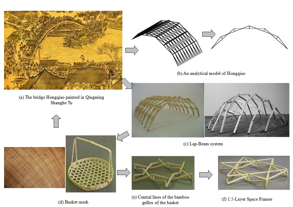 | Figure 1. The idea of the 1.5-Layer Space Frame is inspired frame Hongqiao |
3. The Concept of Configuration
3.1. The Methods to Assemble the Framework
So far, the simplest key part to build a 1.5-Layer Space Frame is found as a king post truss or a similar piece shown in Fig.2(a). Consequently, the basic units can be composed by these key parts in two ways: 1) the Lap-units as shown in Fig.2(b), and 2) the Crossing-units as shown in Fig.2(c). 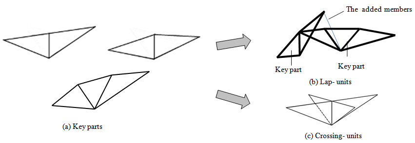 | Figure 2. The key parts and basic units |
The method of Lap-units is that set one end of one or more key parts onto another key part such that the key parts may support one another mutually. Then, a 1.5-Layer Space Frame can be assembled by these basic units in a certain rule. For example, by assembling the Lap-units, 1.5-Layer Space Frames in grids of rectangles and/or triangle-hexagons can be built, as that shown in Fig.3. 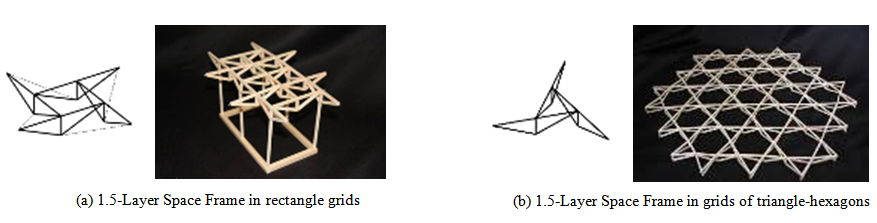 | Figure 3. 1.5-Layer Space Frame with Lap-units |
The method of Crossing-units is that the basic units are assembled by crossing two more key parts together, as shown in Fig.2(c), and then the whole structure can be built by connecting these basic units in a certain assembling rule, such as linking them end to end. Using the Crossing-units, 1.5-Layer Space Frames in grids of rectangles can be assembled in curved and/or plane forms, as that shown in Fig.4. Furthermore, the units may be oriented upside down for free design requirements. 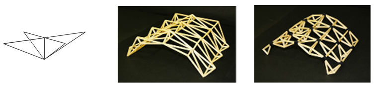 | Figure 4. 1.5-Layer Space Frame with Crossing-Type units |
If the key parts of the Lap-units are replaced by panels, as shown in Fig.5(a), a structural system assembled with panels can be obtained as that shown in Fig.5(b). This structure characterises that the panels are connected one to adjacent ones mutually and configures a reciprocal frame[5,6], which is also a subject of the author[7]. In addition, a structure similar to the assembling method of Lap-units has been built as an archaeological museum in Bibracte Burgundy France in 2008 (Fig.6), which is designed by French architect Paul Andreu and French engineers Bemard Vaudeville and Simon Aubry (RFR first stage and T/E/S/S second stage)[8-10]. But the assembling method of Crossing-units of the proposed system is different from the reciprocal system, and more assembling methods similar to those for space frames are believed to be developed for the 1.5-Layer space frames. In such a context, the 1.5-Layer space frame should be fallen into the category of space frame as a new type of space frame. 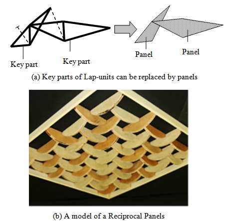 | Figure 5. Reciprocal Panels |
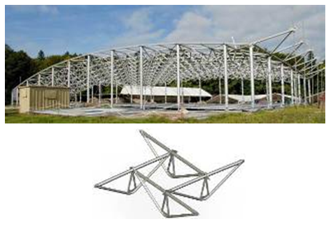 | Figure 6. Structure of the archaeological museum in Bibracte[8-10] |
3.2. Form Design
The 1.5-Layer Space Frames have versatility for form design. In the former sections, 1.5-Layer Space Frame in cylindrical and plane forms are represented. In order to demonstrate its design possibilities, the author with the help of his students, made some study models and 3D-CGs, which their grids and forms are imitated from some designs of culture heritages.
3.2.1. Form Design with Geometrical Grids
Fig. 7 shows a dome of 1.5-Layer Space Frame, and Fig. 8 shows a frame in HP surface, and both of the structures are composed by Crossing-units. These examples represent that the 1.5-Layer Space Frame can be designed in various geometrical forms.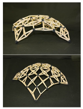 | Figure 7. Dome of 1.5-Layer Space Frame |
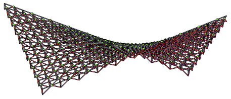 | Figure 8. 1.5-Layer Space Frame of HP surface |
1.5-Layer Space Frame may also be designed in forms of some traditional decorations etc., such as Japanese Kogin. Kogin is a traditional needlework technique for a practical desire of warmth, and the need to strengthen the fabric used in day life. Kogin is recognized by its characteristic blue and white geometric designs, which are embroidered with thick threads on a base fabric[11]. The origins of this technique can be traced to the peasants in the Tsugaru District at the north western tip of Honshu (the main island) Japan in the 1600's. Hirosaki city is the place where the governor of the Tsugaru District located, and the Kokin technique there are called as Hirosaki Kogin. Fig.9(a) shows a piece of the typical design of Hirosaki Kogin, and Fig.9(b) shows an grid plan emerged from the design of Hirosaki Kogin, and Fig.9(c) shows a 3D-CG of 1.5-Layer Space Frames assembled in grids emerged from Hirosaki Kogin. The basic units used to build this frame are mixed by Lap-units and Closing-units. This design proves that the 1.5-Layer Space Frame is suitable for designs with free grids, which it may be difficult to be realized by using double layer space frames.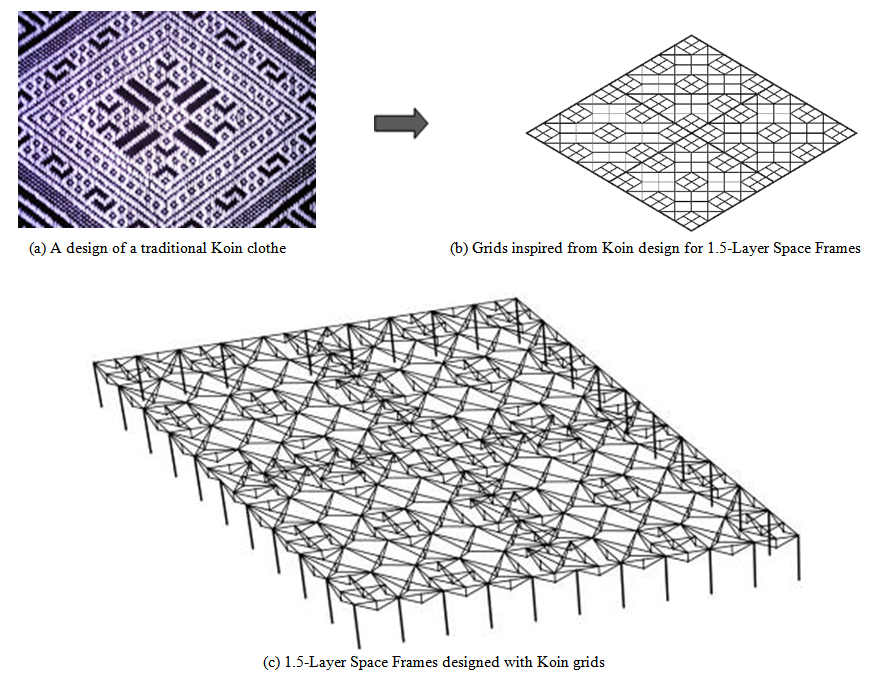 | Figure 9. 1.5-Layer Space Frame with traditional Kokin grids |
3.2.2. Random Grids Generated from Chinese Window Grilles
Since ancient times, the Chinese have been using wooden grilles designs in their windows. The inside of the grilles has traditionally been covered with paper, which is replaced each year on New Year’s Day. Today, we may easily find hundreds even thousands samples of traditional designs of Chinese window grilles. In order to demonstrate the design possibility of the 1.5-Layer space frames, the author designed some frameworks in random grids emerged from the traditional Chinese window grilles as shown in Fig.10. Fig.11 shows the example of the study models. This example represent that the designer can design a 1.5-Layer space frame to represent their feeling and culture heritage. However, more grid patterns are required to develop the designs of the 1.5-Layer Space Frames on aesthetics and ideology.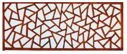 | Figure 10. A design of traditional Chinese window grilles |
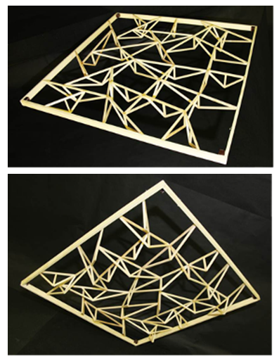 | Figure 11. A 1.5-Layer Space Frame with random grids |
3.2.3. Hybrid Frame System
The 1.5-Layer Space Frames can be constructed together with double layer space frames to make a hybrid structural system. For example, the double layer space frames can be designed as girders supporting around the 1.5-Layer Space Frames. Fig.12 shows such an example in which the space frames of double layers and 1.5 layers work together to cover a big span.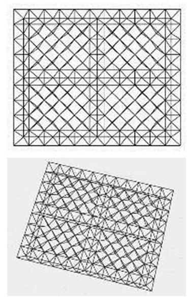 | Figure 12. A 1.5-Layer Space Frames supported by double layer frames |
4. Stability of a 1.5-Layer Space Frame
Because the 1.5-Layer Space Frame consists of fewer members comparing with that of the double layer frames, its structural stability should be demonstrated carefully. Observing Fig.13(a), joints on lines parallel to the line AB or A’B’ make rotational freedoms for the entire structure, if there are not enough supporting around the edges of the structure. However, such a problem may not occur if the structure shape is suitably designed in a curved shape with enough supporting as shown in Fig.13(b). Therefore, a 1.5-Layer Space Frame may not be a geometrically self-stable one, and suitable supports/constraints are necessary to stabilize the structure. On the other hand, a curved 1.5-Layer Space Frame can also be regarded as a single layer space frame (a latticed shell) strengthened by some diagonal members. A latticed shell must be geometrically self-stable one, and therefore a single layer space frame strengthened by some diagonal members, which is a 1.5-Layer space frame, must be a stable structure. However, researches on the mechanical stabilities, such as the buckling behaviours of a 1.5-Layer Space Frame, are remained as important subjects for the further studies. 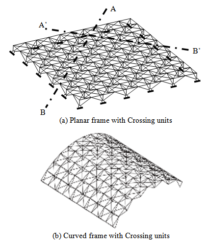 | Figure 13. Planar and curved 1.5-Layer Space Frames with Crossing units |
Consequently, local stabilities, stabilities for members or basic units, are also important topics. It is easy to find that each lower joint of the Lap-units has one degree of freedom in its horizontal direction, which may cause rotation of the key-parts (Lap-unit) around the axes of its upper chords. This degree of freedom can be constrained by suitable connection techniques at the joints or by added members as shown in Fig.2(b). However, for a curved 1.5-Layer Space Frame with Lap-units, which the key-parts are arranged in an inclined direction as shown in Fig.14(a), moment must accuse at the joint due to the vertical load. If the Lap-units are big and heavy enough, the 1.5-Layer Space Frame should be designed in a horizontal plane with its units arranged vertically, such that the vertical loads may act in the surface of the units (Fig.14(b)). For a 1.5-Layer Space Fame with curved surface and inclined units, suitable jointing method should be developed to deal with the moments caused at the joints, or diagonal members should be added to control the rotation the units. Fig.15 shows an example of a curved frame composed by Lap-units with added members constraining the rotation the units.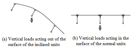 | Figure 14. Section of 1.5-Layer Space Frames with normal and inclined units |
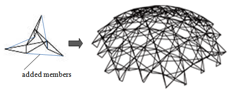 | Figure 15. 1.5-Layer Space Frame with added members to control the unit rotation |
Unlike the method of the Lap-units, the Crossing-units can be linked by pin joints, and the 1.5-Layer Space Frame may be designed in curved and planar form easily, and no moment happen at the joints and members in a theoretical context. However, the stability of a 1.5-Layer Space Frame should be demonstrated with a mechanical manner. If a structure is not a stable one, a linear static mechanical analysis could not be run correctly for the rank of the stiffness matrix is smaller than the number of equilibrium conditions(freedoms of the displacements), and that is the common knowledge. Furthermore, a flat frame with one layer of chords and some diagonal members may be imaged to cause big vertical displacements. In order to demonstrate the stability and overall stiffness (deformation) of a 1.5-Layer Space Frame, linear static analyses are carried out. However, mechanical characteristics and structural design method for the 1.5-Layer Space Frames will be reported in the coming issues.The analytical model of Lap-units, shown in Fig.16, spans 33m with vertical members of 1.5m in length, and all the member section areas are assumed as 100cm2. The member material is assumed as steel with an elastic modulus of 2.1×10⁵N/mm2, and the concentrated load of 18kN is acting vertically at every joint. Every lower joint at the edges of the structure is pinned. Every joint is modelled as pin, but every end of the basic unit is constrained to control its rotation around the upper chords axes. However, calculation for structural design is not carried out, and all these analysis parameters are defined only for investigating the stability of the framework.The analysis results show that the extreme value of the vertical displacement is 4.3cm, which is found around the centre of the structure. Then, the extreme values of member forces are 646kN and -578kN (Fig.17). 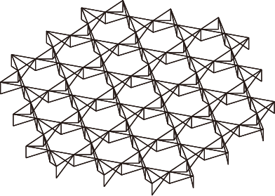 | Figure 16. Analytical model of triangle-hexagons grid |
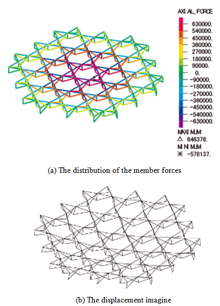 | Figure 17. The analysis results |
Fig.18 shows another example of a 1.5-Layer Space Frame with Crossing-units in grids of rectangles. The analytical model spans 30m with vertical members of 1.5m in length, and all the member section areas are assumed as 50cm2. The elastic modulus of member material is assumed as 2.1×10⁵N/mm2, and concentrated load of 18kN is acting vertically at every joint. Pin supports are set at the lower joints of the edges around the structure. All the joints are pin connections. 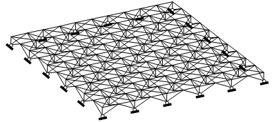 | Figure 18. Analytical model of Crossing-units |
The analysis results of the 1.5-Layer Space Frame with Crossing-units are shown in Fig.19. The extreme values of member forces are 332kN and -473kN, and the extreme value of the vertical displacement is 7.4cm which is found around the centre of the structure.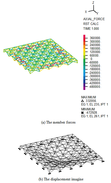 | Figure 19. The analysis results for an analytical model of Crossing-units |
These analysis results demonstrated that the promoted system of 1.5-Layer Space Frame is very stable, and is suitable for big span space structures. However, further researches are necessary to shed light on the structural features and structural design manners. In addition, comparison of the structural features between the 1.5-Layer Space Fames and the space frames of double-layers and/or single layer are remained for further researches.
5. Conclusions
The 1.5-Layer Space Frame was invented while researching an ancient Chinese wooden bridge from the Song dynasty (960-1127 A.D.), which was drawn in the famous Chinese painting Qingming Shanghe Tu. This new framework promotes original free form designs and requires very few members.The author categorized the 1.5-Layer Space Frame as a type of space frame, and defined it as: A 1.5-Layer Space Frame is a structure composed by bars pined with two layers of joints, and there is no member linking two or more joints in one certain layer. Consequently, the author promotes to re-classify the types of space frames into: 1) Double and multi-Layers, 2) 1.5-Layer, and 3) Single Layer Space Frames.In order to demonstrate the stability and deformation features of a 1.5-Layer Space Frame, mechanical analyses were carried out and the results show that the promoted system is very stable and suitable for big span space structures. Therefore, the 1.5-Layer Space Frames are able to support large span buildings. The system of 1.5-Layer Space Frame has versatility for form design, such that the designer can use it to represent their feeling and culture heritage. However, further researches are required to demonstrate the mechanical characteristics and develop the structural design methods of the 1.5-Layer Space Frames.Furthermore, the author promotes an ontology and methodology for practical structural design inspired by ancient structures to enhance modern structural design with aesthetic originality.
References
| [1] | Pei-Shan Chen, “A Study Report on an Ancient Wood Bridge Hongqiao”, Structural Engineering International, 2008. 2, pp84-87. |
| [2] | Pei-Shan Chen, “Configuration and Structural Principle of an Ancient Chinese Wood Bridge Hongqiao”, Proceeding of IASS2007, 2007. Dec. |
| [3] | Pei-Shan Chen, “A study on the geometrical configuration of an ancient wooden bridge in Qingming Shanghe Tu”, Proceeding of IASS2010, Shanghai, 2010. Nov. |
| [4] | Pei-Shan Chen, “A Report on the Innovation of 1.5-Layer Space Frames”, Proceeding of IABSE IASS 2011, London, 2011.Sep. |
| [5] | Olga Popovic Larsen, “Reciprocal Frame Architecture”, Elsevier Ltd., 2088. |
| [6] | José Sánchez, Félix Escrig, “Frames Designed by Leonardo with Short Pieces An Analytical Approach”, International Journal of Space Structures, Volume 26, No. 4/December 2011, pp303-311. |
| [7] | Pei-Shan CHEN, “A Report on the Innovation of Reciprocal Panel System”, Proceeding of IASS-APCS 2012, Seoul, 2012.May. |
| [8] | Simon Gelez, Simon Aubry, Bernard Vaudeville, “Nexorade or Reciprocal Frame System Applied to the Design and Construction of a 850m2 Archaeological Shelter Archaeological Shelter”, International Journal of Space Structures, Volume 26, No. 4/December 2011, pp303-311. |
| [9] | http://www.bibracte.fr/fr/entrez-dans-les-coulisses/experimenter/couverture-de-fouilles_04_02_04.html |
| [10] | http://www.tess.fr/fr/projets-references/structures-mobiles/bibracte |
| [11] | Setsu Maeda, Tsugaru Kogin-sashi (Kogin-zashi) Japanese Tsugaru Kogin Needlework, T. Seto (1976). |
 Abstract
 Reference
 Full-Text PDF
 Full-text HTML