-
Paper Information
- Paper Submission
-
Journal Information
- About This Journal
- Editorial Board
- Current Issue
- Archive
- Author Guidelines
- Contact Us
Applied Mathematics
p-ISSN: 2163-1409 e-ISSN: 2163-1425
2018; 8(1): 9-18
doi:10.5923/j.am.20180801.03

Singularity Penetration with Unit Delay (SPUD)
 Abstract
 Reference
 Full-Text PDF
 Full-text HTML
Timothy Sands1, Jae Jun Kim2, Brij Agrawal2
1Department of Mechanical Engineering, Stanford University, Stanford, USA
2Department Mechanical and Aerospace Engineering, Naval Postgraduate School, Monterey, USA
Correspondence to: Timothy Sands, Department of Mechanical Engineering, Stanford University, Stanford, USA.
| Email: |  |
Copyright © 2018 Scientific & Academic Publishing. All Rights Reserved.
This work is licensed under the Creative Commons Attribution International License (CC BY).
http://creativecommons.org/licenses/by/4.0/

This manuscript reveals both the full experimental and methodical details of a most-recent patent that demonstrates a much-desired goal of rotational attitude control actuators, namely extremely high torque without mathematical singularity and accompanying loss of attitude control. The paper briefly reviews the most recent literature, and then gives theoretical development for implementing the methods described in the patent to compute a non-singular steering command to the actuators. The theoretical developments are followed by computer simulations used to verify the theoretical computation methodology, and then laboratory experiments are used for validation on a free-floating hardware simulator.
Keywords: Rotational attitude control, Momentum actuator, Singularity penetration: SPUD
Cite this paper: Timothy Sands, Jae Jun Kim, Brij Agrawal, Singularity Penetration with Unit Delay (SPUD), Applied Mathematics, Vol. 8 No. 1, 2018, pp. 9-18. doi: 10.5923/j.am.20180801.03.
Article Outline
1. Introduction
- Two objectives dominate consideration of control moment gyroscopes (CMGs) as actuators for rotational maneuvers: High torque (or equivalently momentum) and singularity-free operations. Utilizing a 3/4 CMG skewed-pyramid the optimal singularity-free configuration is revealed. Next, this paper develops a decoupled control strategy to reduce the remaining singular conditions. Analysis and simulation is provided to justify the argument with experimental verification performed on a free-floating satellite simulator. Furthermore, a singularity penetration algorithm is developed, simulated, and experimentally proven to fly through singularities even without singularity reduction.The study in this paper utilizes the 3/4 skewed pyramid (Fig. 1) for rapid rotaional maneuvers. Optimizing spherical singularity-free momentum results in setting skew angle β = 90° yielding bidirectional +2H singularity free momentum capability in roll and yaw with +1H singularity free momentum capability in pitch. The singular surfaces collapse into structures that slightly resemble a doughnut with a ring in the center. This optimal singularity-free geometry is established as the baseline geometry. Further this paper will elaborate methods to eliminate/reduce the remaining depicted singularities. This configuration will be experimentally verified later in the paper. Research concentrates on the inner lining of the doughnut-like singular surface in the momentum space. Methods to eliminate/reduce or penetrate this wall of singularity could open the entire momentum space for rapid rotational maneuvers singularity free. Despite singularity issues, CMG research began in 1960s for large satellites like SKYLAB. Computers of the time could not perform matrix inversion real time. Simple systems that did not require matrix inversion were an obvious choice. Otherwise algorithmically simple approximations must have been available for the system chosen. Singularity avoidance was researched a lot in the 1970s and 1980s [1-5].Singularity avoidance was typically done using a gradient method [5, 6]. These gradient methods are not as effective for Single Gimbaled CMGs (SGCMGs) as for Double Gimbaled CMGs (DGCMGs). Margulies was first to formulate a theory of singularity and control [7] including the geometric theory of singular surfaces, generalized solution of the output equation, null motion, and the possibility of singularity avoidance for general SGCMG systems. Also in 1978 Russian researched Tokar published singularity surface shape description, size of workspace, and considerations of gimbal limits [8]. Kurokawa identified that a system such as a pyramid type CMG system will contain an impassable singular surface and concluded systems with no less than 6 units provide adequate workspace free of impassable singular surfaces [9]. Thus MIR was designed for 6 SGCMG operations. Continued research aimed at improving results with less than 6 CMGs emphasized a 4 CMG pyramid. Many resulted in gradient methods that regard passability as a local problem that proved problematic [8, 10, 11]. Global optimization was also attempted but proved problematic in computer simulations [12]. Difficulties in global steering were also revealed in Bauer [13]. NASA [14] compared six different independently developed steering laws for pyramid type single gimbaled CMG systems. The study concluded that that exact inverse calculation was necessary. Other researched addressed the inverted matrix itself adding components that make the matrix robust to inversion singularity [15, 16] as extensions of the approach to minimize the error in generalized inverse Jacobian calculation [20]. Path Planning is another approach used to attempt to avoid singularities that can also achieve optimization if you have knowledge of the command sequence in the near future [17-19]. Another method used to avoid singularities is to use null motion to first reorient the CMGs to desired gimbal positions that are not near singular configurations [20]. Despite the massive amount of research done on CMGs, precision control w/ CMGs is still an unsolved problem [21-23] and is the focus of considerable recent research. Mathematical formulation of the problem of rotational attitude control begins with techniques that utilize the underlying physics to inspire control designs, and these designs require math models of the system, sensors, and actuators. Astrom and Wittenmark described such designs in their textbook on adaptive control [24]. Slotine [25, 26] reveals adaptive control techniques that utilize system math models in their adaptive strategies. Fossen [27] subsequently improved Slotine’s technique with mathematical simplifying problem formulation, and Sands [28, 30-34] and Kim [29] developed further improvements to the algorithm based on Fossen’s problem formulation followed by Nakatani [35, 36] and Heidlauf-Cooper [37, 38], but alas these improvements were not revealed in time for publication in Slotine’s text. Particularly relevant to the actuator models, Wie [39] elaborated singularities that exists in the control actuators that can exacerbate or defeat the control design as articulated [40-43] and solved by Agrawal [44]. Lastly, Sands [45-47] illustrated ground experimental procedures and on-orbit algorithms for system identification of system math models, while this research article illustrates analytical research of actuator singularities, followed by validation via simulations, and verification using ground experiments.
2. Materials and Methods
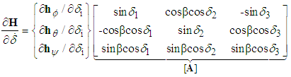
- Control moment gyroscopes are momentum exchange devices. Commands are sent to the CMG to change its momentum resulting in an equal and opposite change in system momentum to maintain system equilibrium. In order to achieve a specified output torque from an array of CMGs, a command must be submitted to the gimbal motor. Torque is related to rate of change of angular momentum via Newton-Euler, resulting in the mathematical relationship between gimbal commands and torque output called a CMG steering law. The three steering law equations for 3-axis control are combined in matrix form. Equations (1)-(4) derive this relationship for i=n CMGs normalized by one CMG’s worth of momentum (1H). CMGs are inclined such that their gimbal planes form skew angles,
 with respect to the xy plane
  The [A] matrix (containing gimbal angles,
  and skew angles,
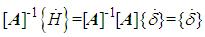
  ) must be inverted to find the required CMG gimbal command
  for commanded output torque per equation (4). Begin by writing equations for each momentum vector in xyz
  coordinates for 3 CMGs normalized by 1H, one CMG’s worth of momentum.
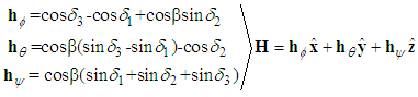 | (1) |
 | (2) |
 causing an equal and opposite change in momentum on the system. For n CMGs, the general relation is:
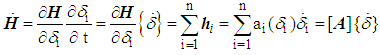 | (3) |
 | (4) |
 | (5) |
2.1. The 3/4 Skewed CMG Array
- The 3/4 CMG array modifies the commonly studied 4 CMG skewed pyramid [24]. A minimum of 3 CMGs are required for 3-axis control, and the fourth it often used for singularity avoidance. With the 3/4-array, only 3 CMGs are utilized for active attitude control with the fourth CMG held in reserve for robust failure properties. Experimental verification will be provided in later sections utilizing a system testbed with a 3/4 CMG array containing a balance mass in the place of the fourth CMG. Many past researchers have approached CMG singularity avoidance by modifying the [A] matrix itself to make it invertible without singularities. Instead, consider readdressing two of the most fundamental mathematical steps: the optimal skew angle and the combination of the three coupled equations of motion into a system of equations represented in matrix form.
2.2. Optimal Singularity-free Skew Angle
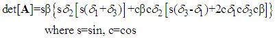
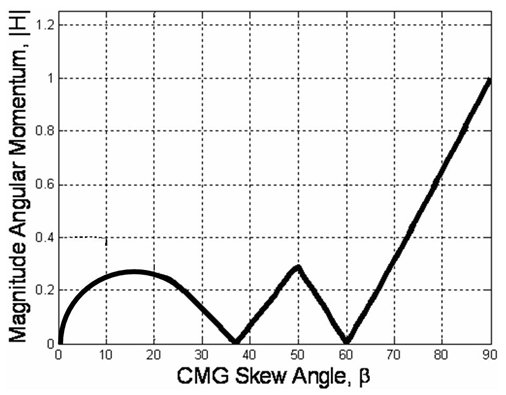
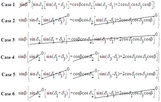
- Consider the six cases listed that permit the determinant of the [A] matrix to be zero. Retaining the skew angle as a iterated variable, loop through gimbal angles until a gimbal angle combination meets the criteria for det[A]=0. For gimbal combinations that meet the criteria, calculate the angular momentum components in each of the three axes and resultant angular momentum magnitude. After iterating for all gimbal combinations at a certain skew angle, the minimum magnitude of angular momentum at a singular condition is the first place a momentum trajectory hits a singularity when departing the origin. This analysis was performed [25] resulting in the optimal singularity-free skew angle of ninety degrees (Fig 1). At this skew angle, the largest momentum space is available for singularity-free torque generation. This is clearly visible in the heuristic plot of singular surfaces for iterated skew angle (Figure 2).
 | Figure 1. ITERATION: Optimum singularity-free CMG skew angle, β |
 | Figure 2. Heuristic analysis varying skew angle, β for a 3/4 CMG skewed array. β was varied in 5° increments from 0° to 90° identifying the trend represented here by three primary plots with 3H & 0H singular surface lightened to enable visualization of 1H & 2H singular surfaces: β=70° (top), 80° (lower left), 90° (lower right) |
2.3. Mixed Skew Angles
- Typically, skewed CMG arrays utilize identical skew angles for each CMG
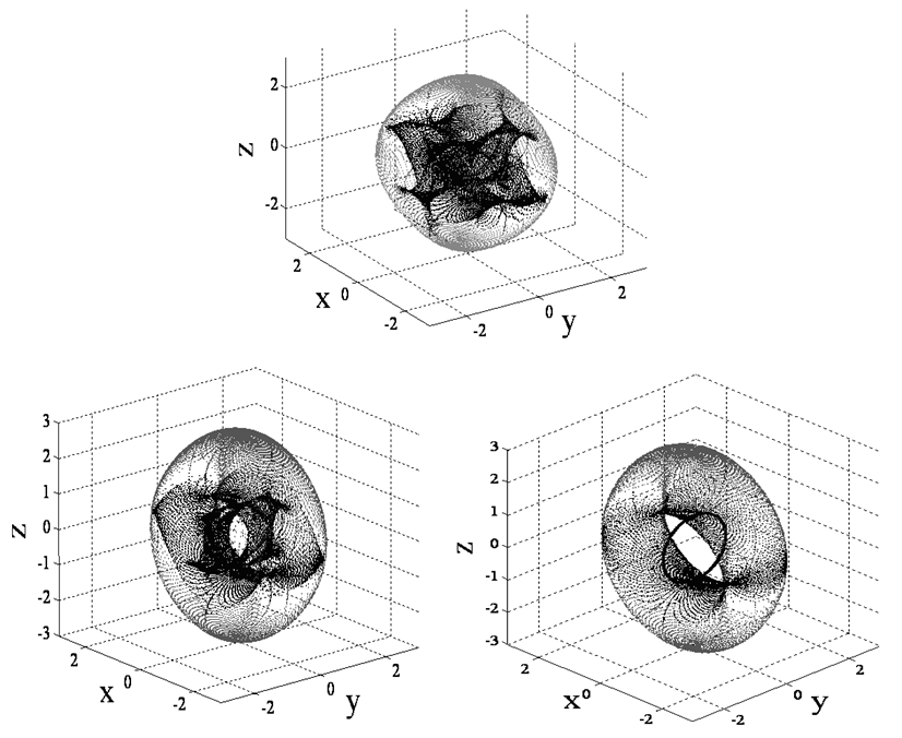
 By using mixed skew angles, the singularity-free “football” shaped space can be reoriented to place the maximum momentum direction in the yaw direction. Six possible momentum reorientations are possible by laying down momentum planes from ninety degrees to zero degrees as listed in Figure 3 resulting in rotations of the momentum space depicted respectively in the following order per Figure 4. Simulation and experimental verification of the optimum singularity-free skew angle and mixed skew angle momentum space rotations may be found in ref [40-43].
 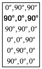 | Figure 3. Six possible combinations of mixed skew angles laying one or two momentum cutting planes from 0° to 90°. Corresponding singular hypersurfaces are depicted in respective order in Fig. 5 |
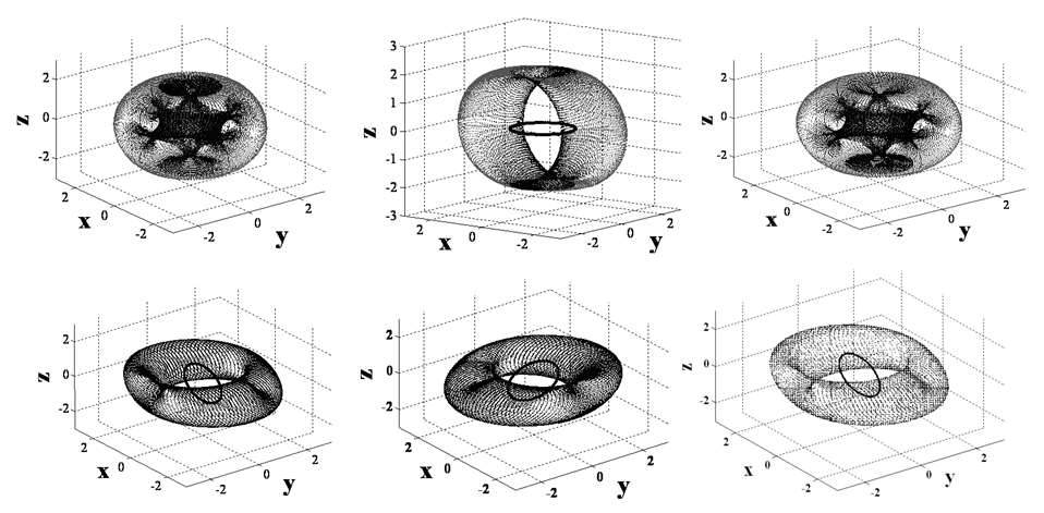 | Figure 4. Singular hypersurfaces resulting from 6 possible combinations of mixed skew angles. Singular surfaces from upper left correspond to sequence of mixed skew angles per Fig. 4 |
2.4. Decoupled Control Analysis
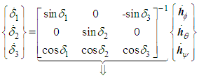
- In this section, we derive a strategy dubbed “decoupled control” where we take advantage of the simplifications that arise from the optimum singularity free skew angle,
 Substituting the [A] matrix with
  into equation (4) yields:
 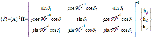 | (6) |
 | (7) |
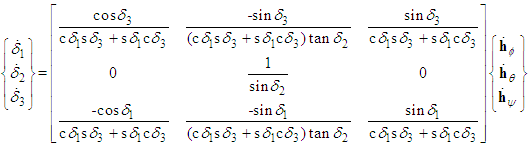 | (8) |
 momentum-change equation has become decoupled from the
  equations. Pitch momentum is determined completely by gimbal #2. The pitch equation may be separated from the matrix system of equations. The benefit is the elimination of singular gimbal commands for CMGs that are not in geometrically singular gimbal angle positions. Consider what happens if the first and third CMGs enter a singular angle combination that satisfies
 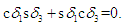 This would not result in singular commands to CMG 2. CMG gimbal 2 would receive the following normal steering command:
  | (9) |
3. Results
3.1. Decoupled Control Simulation
- Large yaw maneuvers were simulated using typical coupled control and compared to the proposed decoupled control strategy. Firstly a +50° yaw maneuver is followed immediately by -50° yaw maneuver then regulation at zero. The results of both methods are displayed in Figure 5. Notice the coupled implementation of the Moore-Penrose pseudoinverse results in dramatic roll commands each time the momentum trajectory strikes the singular surface.
 | Figure 5. SIMULATION: Comparison of normalized momentum trajectory for simple yaw maneuvers using typical coupled control (thick-dashed line) Vs. decoupled control (thin line). Notice large pitch (θ) errors when the trajectory passes through the singularity surface |
3.2. Singularity Penetration Algorithm
- Next, consider that singularity reduction as presented is restricted to geometric configurations (CMG skew angles) that permit control decoupling. Instead consider penetrating the singular surface without loss of attitude control. Attitude control is lost when the closed loop control law tries to invert a rank deficient [A] matrix. When the determinant, equation (5) reaches a critical low absolute value, the closed loop law is augmented to include a unit-delay activated at this critically low value. As the momentum trajectory approaches the singularity, increasingly high gimbal rates are required. When the unit-delay is switched on, the previous valid (non-singular) value is held until the singularity has been penetrated. Then, the nominal closed-loop control (inversion of [A]) continues to control the spacecraft. In essence, we are “ignoring” the anomalous transient as we pass through the singularity. Henceforth, the technique is referred to as SPUD: singularity penetration w/ unit delay. Figure 6-Figure 8 depicts results of simulated 50° yaw maneuvers with and without SPUD. The fully coupled control is implemented here without the decoupled control scheme used earlier to reduce singularities. The simulations indicate that SPUD is effective even without reduced singularities via decoupled control, thus SPUD is more generically effective for other geometric configurations (CMG skew angles).
 | Figure 6. SIMULATION: (Top) Comparison of Euler angles for 50° yaw maneuver with & without singularity penetration with unit delay (SPUD); (Bottom) Comparison of tracking errors for 50° yaw maneuver with & without singularity penetration with unit delay (SPUD) |
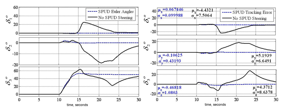
 | Figure 7. SIMULATION: (Top) Comparison of det[A] and normalized momentum magnitude for 50° yaw maneuver with & without singularity penetration with unit delay (SPUD); (Bottom) Comparison of gimbal rates for 50° yaw maneuver with & without singularity penetration with unit delay (SPUD) |
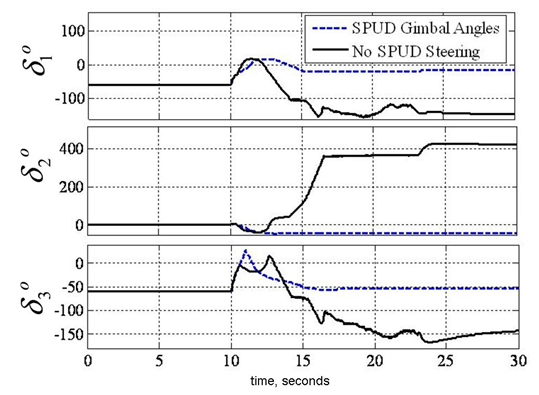 | Figure 8. SIMULATION: Comparison of gimbal angles for 50° yaw maneuver with & without singularity penetration with unit delay (SPUD) |
3.3. Experimental Verification
- Experiments were performed with decoupled control to maximum momentum capability about the yaw axis. First note Figure 9 (left) displays the ability of decoupled control steering to penetrate the singular surface associated with the coupled [A] matrix of CMG gimbal angles and skew angle. This attribute is exploited with an aggressive yaw maneuver (Figure 9 right). The commanded maneuver angle from [2] was increased 700% from ± 5° in 4 seconds to ± 35° in 10 seconds. This demands significantly more momentum change specifically about yaw. Figure 9 displays the required maneuver is achieved without incident. Notice that the coupled [A] matrix was singular twice during this drastic maneuver, which would have normally resulted in loss of attitude control.Typical coupled control steering would have resulted in loss of spacecraft attitude control. Instead, with decoupled steering, you will notice a nice maneuver despite singular [A] matrix. Attitude control is not lost at any time. Also notice the extremely high magnitude of normalized momentum (nearly 3H) achieved singularity free. Next, experiments were performed with typical coupled control and singularity penetration algorithm, SPUD. In the comparative slides, you’ll immediately notice the experiment performed without SPUD was terminated early (after about 25 seconds) to prevent hardware damage due to loss of attitude control.
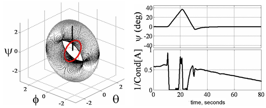 | Figure 9. EXPERIMENTATION: (Top) Demonstrate ability to pass cleanly through the singular surface at 1H using proposed decoupled control. (Bottom) Yaw Euler angle and 1/cond[A] versus time (secs) for +35° yaw in 10 seconds, -35° yaw in 10 seconds performed with decoupled control steering |
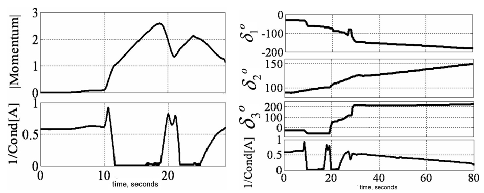 | Figure 10. EXPERIMENTATION: Momentum Magnitude and 1/cond[A] (top) versus time (secs) for +35° yaw in 10 seconds, -35° yaw in 10 seconds performed with decoupled control steering. Plot is zoomed to emphasize momentum increase/decrease despite singular [A] matrix with decoupled control. Also, note the maneuver drastically exceeds 1H momentum. (bottom) Gimbal angles and 1/cond[A] versus time (secs) for +35° yaw in 10 seconds, -35° yaw in 10 seconds performed with decoupled control steering. Note smooth gimbal action despite singular [A] matrix with decoupled control |
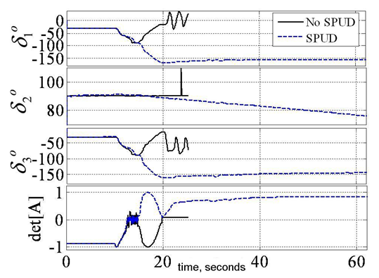
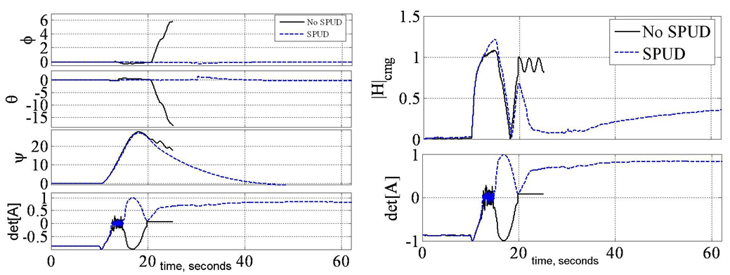 | Figure 11. EXPERIMENTATION: Yaw Euler angle in degrees (top) and det[A] versus time (secs) for +30° yaw in 8 seconds immediately followed by -30° in 8 seconds performed with and without SPUD. (Bottom) Normalized momentum magnitude (top) and det[A] (bottom) versus time (secs) for +30° yaw in 8 seconds, immediately followed by -30° in 8 seconds performed with and without SPUD. Note momentum increase/decrease despite singular [A] matrix with decoupled control. Also, note the maneuver drastically exceeds 1H momentum |
 | Figure 12. EXPERIMENTATION: Gimbal angles (top) and det[A] (bottom) versus time (secs) for +30° yaw in 8 seconds immediately followed by -30° in 8 seconds performed with and without SPUD. Note smooth gimbal action despite singular [A] matrix with SPUD |
4. Discussion of Conclusions
- This paper reveals the details of a most-recent patent [44] that demonstrates a much desired goal of rotational attitude control with CMGs, extremely high torque without mathematical singularity thus without loss of attitude control. CMG geometry is optimized to yield the maximum singularity-free momentum space. Using a proposed decoupled control strategy, further singularity reduction is achieved. Finally, utilizing a singularity penetration algorithm, momentum trajectories cleanly pass through remaining singular surfaces without loss of attitude control bestowing the entire momentum space to the attitude control engineer. These claims are introduced analytically and promising simulations are provided. Finally experimental verification is performed demonstrating dramatic yaw maneuvers that pass through singular surfaces that would render loss of attitude control using typical coupled control techniques. A typical 3/4 CMG array skewed at 54.73o yields 0.15H. Increasing skew angle to ninety degrees and utilizing the proposed singularity penetration technique, 3H momentum is achieved about yaw, 2H about roll, and 1H about pitch representing performance increases of 1900%, 1233%, and 566% respectfully.
5. Patents
- Agrawal, B., Kim, J., Sands, T., “Method and apparatus for singularity avoidance for control moment gyroscope (CMG) systems without using null motion”, U.S. Patent 9567112 B1, Feb 14, 2017.
ACKNOWLEDGEMENTS
- Jae June Kim and Brij Agrawal collaborated to conceive and design the experiments, analyze the data, and interpret the results.