Shichikha J. M1, Bitok J1, Manyonge A. W2, Sang’ K. N1
1Department of Mathematics and Computer Science, University of Eldoret, 1125, Eldoret, Kenya
2Department of Pure and Applied Mathematics, Maseno University, Maseno, Private Bag, Kenya
Correspondence to: Shichikha J. M, Department of Mathematics and Computer Science, University of Eldoret, 1125, Eldoret, Kenya.
| Email: |  |
Copyright © 2012 Scientific & Academic Publishing. All Rights Reserved.
Abstract
The problem under investigation is to determine the various losses that commonly occur in pipe system components. We attempt to give an account for the analysis of head loss on additional components particularly in the case of abrupt expansion of the pipes and how to minimize the losses by reconverting the kinetic energy into flow energy. The head loss term hL account for any energy loss associated with the flow. This loss is a direct consequence of the viscous dissipation occurring through-out the fluid in the pipe.
Keywords:
Head Loss, Kinetic Energy, Flow Energy, Viscous Force
Cite this paper: Shichikha J. M, Bitok J, Manyonge A. W, Sang’ K. N, Head Loss Analysis in Pipe System Components, Applied Mathematics, Vol. 3 No. 5, 2013, pp. 160-162. doi: 10.5923/j.am.20130305.02.
1. Introduction
We have two types of practical methods used to describe the variety of fluid mechanics; the finite control volume analysis and differential analysis of fluid flow.[1] Distinguishes the two analysis as follows; finite control volume analysis of the behavior of the content to a finite region in space (control volume).The concept of a control volume and system occupying the same region of space at an instant are key element in the derivation of the control volume analysis. The use of pipe bends may introduce increased cross sectional flow velocities thus making the flow more non-uniform at the bend exit and causing flow separation[2].Control surface area integrals allow for surface distributions of flow of variables. However for simplicity we often assume that flow variables are uniformly distributed over cross section of a pipe. In general an increase in velocity is accompanied by a decrease in pressure and vice-versa. Several experimental studies have been performed including an analysis of varied circular arc elbow pressure losses[3] and an analysis of varied meter bends[4]. The computational study of internal flows in general has been very popular. The study of turbulent internal pipe flows in curved sections of both circular and square cross sections has been performed, [5,6]. In these circumstances we need to develop relationships that apply at a point or at least in a very small region (infinitesimal volume) within a given flow fluid. This approach which involves an infinitesimal control volume is referred to as differentialanalysis since the governing equations are differential equations.The pressure decrease needed (to accelerate the fluid through construction) cause fluid velocity to increase.These differential equations are therefore soft in their own specified context with the suitable bonding conditions and symmetries to simplicity.
1.1. Mathematical Model for Pipe System Components
We consider the horizontal straight pipe with varying cross-sectional area as shown in the figure below. The pipe is insulated against heat exchange and consequence heat changes. We analyze head loss or pressure drop in abrupt expansion, contraction diverging pipe system.The model diagram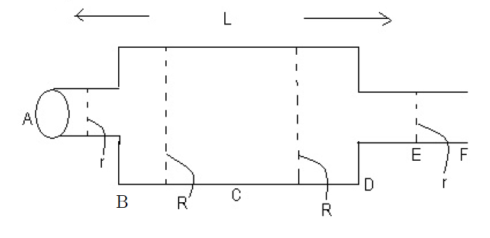 r1, R respective radii.Region L is straight and lying horizontally along the direction of x-axis. The centre of axis has along the horizontal axis.
2. Abrupt Expansion
When the fluid suddenly leaves the smaller pipe and enters the wider part of the pipe there is a sudden deceleration of the fluid and the fluid being unable to move in sharp corners, it tears the boundary at the enlargement so that eddy currents are developed and these eddies dissipate a large amount of fluid energy and expansion losses occur.Hence from the law of conservation of mass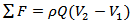 | (1) |
But for incompressible flow 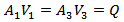 Leading to
 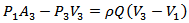 | (2) |
When  and V refers to the fluid density, cross sectional area of the pipe and speed of fluid respectively.From the equation we find
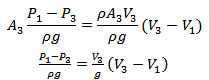 | (3) |
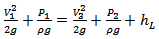
Applying Bernoulli’s equation to a horizontal streamline along the centerline of the pipe, and ignoring friction losses between the fluid and the pipe walls, but including the head loss at the expansion hL, 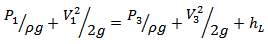 Thus
Thus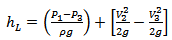 | (4) |
and using equations (3) and (4)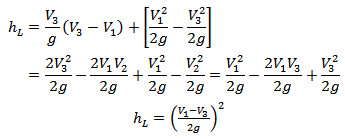 | (5) |
The loss is a function of the square velocity as in turbulent flow[7].Exit flow from a pipe into a large reservoir is similar to a sudden expansion with  So the loss then becomes
 | (6) |
At the point F in the pipe, the pressure P0 is uniform, the equations of continuity, momentum, energy and stagnation pressure are | (7) |
 | (8) |
 | (9) |
and | (10) |
Simplifying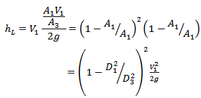 | (11) |
Thus the equation for theoretical head loss is modified to the form | (12) |
Where k is an experimental value equal to or less than and D is the diameter of the pipe.From equation (5), the head loss between the points D and F is  | (13) |
Where and Ac is cross sectional area of vena contracts coefficient of contraction.For flow from a large reservoir through a pipe with square entry
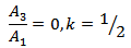 Hence the final equation for calculating head loss arising from abrupt contraction without any re-entry is given by
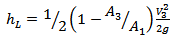 | (14) |
Where . As
. As  the value of k tends to 0.5 and this corresponds to flow from a large reservoir into a sharp edged pipe provided that the end of the pipe does not protrude into the reservoir.
2.1. Graphical Representations for Losses Coefficient for an Abrupt Expansion, and an Abrupt Contraction
This loss is based on velocity head in the small pipe.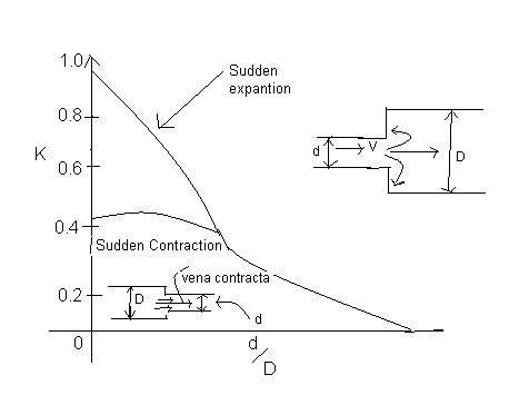
3. Conclusions
The analytic methods of control volume and differential methods can be used to find a balance in forces in pressure, weight and friction. Fluid particles can be taken as discrete particles and the fluid flow phenomenon in abrupt expansion and contraction can be simplified by applying the modified equation, from the general concepts of fluid mechanics like Bernoulli and Hagen-Poiseiulle equations. The head loss term is seen to increase proportionally with the velocity in the pipe.
ACKNOWLEDGEMENTS
The authors wish to thank the University of Eldoret and Maseno University for enabling them to carry out this research. In particular the corresponding author wishes to thank The University of Eldoret for exposing him to university teaching and research which enabled him to attend ICAFD-2012 in Botswana at which the paper was presented. We also thank the organizers of the conference at the University of Botswana for providing accommodation to the corresponding author during the conference.
References
| [1] | Morison, B.R. et.al. : Fundamentals of fluid mechanics, 3rd Edition, John Wiley and Sons, Inc. New York, 1982. |
| [2] | J.T Haskew and M.A.R Sharif, Evaluation of varied pipe bends. |
| [3] | Ito, H and Imai, K. Pressure losses in varied elbows of a circular cross section. Transactions of the ASME, series D, Sept. 1966, pp 684-685. |
| [4] | Dimmock, N.A Cascade corners for ducts of circular cross sections. Br. Chem Eng 1957 2(6), 302-307 |
| [5] | Cheng, G.C and Farokhi, S. on turbulent flows dominated by curvature effects. Forum on turbulent flows, ASME-FED 112,1991,1-8. |
| [6] | Mc Connaughey, P…., Cornelison, J… and Barker, L. The prediction of secondary flow in curved ducts of square cross section. AIAA paper 89-0276, January 1989. |
| [7] | Hamill L.: Understanding hydraulics, 2nd Ed, Palgrave Publishers, New York, 2001. |
 Abstract
 Reference
 Full-Text PDF
 Full-text HTML