Advances in Life Sciences

p-ISSN: 2163-1387    e-ISSN: 2163-1395

2011;  1(2): 40-44

doi: 10.5923/j.als.20110102.07

Optical Coherence-domain Imaging of Subcutaneous Human Blood Vessels in vivo

Sergey G. Proskurin

Biomedical Engineering, Tambov State Technical University, Tambov, 392000, Russia

Correspondence to: Sergey G. Proskurin , Biomedical Engineering, Tambov State Technical University, Tambov, 392000, Russia.

Email:

Copyright © 2012 Scientific & Academic Publishing. All Rights Reserved.

Abstract

Experimental methods of Optical Coherence Tomography (OCT) are applied for two-dimensional mapping of subcutaneous human blood vessels. Structural images of in vivo human finger and human palm macro vessels (0.2-1.0 mm) before and after optical clearing using the modified low power rapid scanning optical delay line are presented. Images are scanned with 12 µm minimum spatial resolution. The described modifications enable to apply low power (0.4-0.5 mW), low noise broadband near infrared light source and to obtain structural images with detection of not only reflected but also multiply scattered coherence-gated photons. The achieved transcutaneous probing depth is about 1.6-1.8 mm.

Keywords: Optical Coherence Tomography (OCT), Low Power Rapid Scanning Optical Delay Line, Optical Clearing, Differential Imaging, Blood Vessels Visualization, Coherence Probing Depth (CPD)

Cite this paper: Sergey G. Proskurin , "Optical Coherence-domain Imaging of Subcutaneous Human Blood Vessels in vivo", Advances in Life Sciences, Vol. 1 No. 2, 2011, pp. 40-44. doi: 10.5923/j.als.20110102.07.

1. Introduction

Optical Coherence Tomography (OCT)[1] is the new, important and fast developing modality which is based on the principles of scanning low coherence interferometry (LCI) and optical coherence-domain reflectometry[2]. Depth discrimination of multiply scattered light is performed due to application of a broadband light source. It could be a superluminescent diode (SLD), femtosecond pulsed laser or a swept source. Transversal resolution of OCT images is chosen by selecting focusing optics with different numerical apertures in the sample arm. Confocal microscopy principle is utilised in this case when a fibre tip works as a pinhole. Rapid low-coherence devices can be made on the basis of fibre optic Michelson interferometer with the rapid scanning optical delay line (RSOD)[3-7] in the reference arm (RA). By detection the phase shift of the interference fringes of consecutive A-scans it is possible to detect blood flow in capillaries, of about 20 – 70 μm in diameter, in human skin in vivo sing 5 mW broadband source[6]. Simultaneous intensity, birefringence and flow measurements into the depth of about 1.0 - 1.2 mm was demonstrated in the upper part of a large blood vessel and in capillaries of a human finger[7,8]. At the same time very important problem of visualisation of subcutaneous human macro blood vessels, of about 1 mm in diameter, has not been solved till recently[9].
Note that further increase of the coherence probing depth (CPD) was investigated using the transitional mode between single backreflection and diffuse wave spectres copy by LCI only. Particle dynamics study of highly scattering media was used utilising singly scattered, multiply scattered and diffuse light detection[10]. The probing depth of the coherence-gated detection of multiply scattered light in this study has reached 1.5 – 2 mm. Scattering properties of the suspension were similar to those of biological tissue.
In this paper we describe several modifications of the rapid scanning optical delay (RSOD) to apply a low power (0.5 – 0.2 mW) irradiation of a broadband infrared light source, superluminescent diode in time domain OCT system [9]. These modifications enable to utilise coherence-gated transitional multiply scattered mode to visualise human finger and human palm macro blood vessels with diameter of about 0.2 - 1 mm. Topical application of the optical clearing material[11] have been used to visualise structural signal from the blood, which appears inside the vessel after hand exercise only.

2. Materials and Methods

Figure 1 shows the schematic of the experimental set-up based on the scanning fibre optic Michelson interferometer with two 1x2 and one 2x2 fibre couplers.
Light from the sample arm (SA) goes through the system of lenses and is focused on the sample at the distance of about 5 cm from the SA scanning mirror (SM). The transversal resolution becomes respectively low, Ltr=70 μm, to compare with other systems utilising focusing optics with high numerical aperture[6,7]. Confocal parameter in this case is about 3.5 mm. Choice of low numerical aperture of the sample arm optics is a compromise between lateral resolution and the probing depth[10]. Despite the loss of the lateral resolution this approach enables additionally discriminate backscattered and backreflected photons from multiply and diffusely scattered ones.
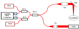
Figure 1. Experimental setup assembled on the basis of single mode fibre optic Michelson interferometer. SLD, superluminescent diode; FC1, FC2, FC3, fibre couplers; D1 and D2, balanced detectors; Red, red light pointing diode laser; CL, OL, optical lenses; SM, scanning mirror; ODL, optical delay line
Transversal sample arm scanning is performed by a Galvano scanner what is essential for in vivo application to compare with application linear scanning stages. The sample arm design also gives possibility to collimate the light and put an additional lens close to the sample. This increases transversal resolution at the upper layers, but does not give possibility to discriminate multiply scattered coherence-gated photons and to visualise transcutaneous structures deeper than 1.0 - 1.2 mm[7].
The described approach increases CPD, but compromises spatial resolution. Yet, it is still enough to study nails and skin layered structures. Imaging of the structures like skin and nails is important in dermatology to study healthy, diseased, burned tissue. Imaging of subcutaneous blood vessels into the full depth of the lumen is necessary to study vessel abnormalities like embolism and aneurysm.
Figure 2 shows the modified implementation of the Fourier-domain scanning grating based double pass optical delay line (RSOD). This implementation is different from the similar ones described before[4,5]. After the collimator near infrared light (λ = 1.3, 1.5 μm) goes to the edge of the diffraction grating (GR) positioned at the tunable angle γ = 7-8° [4, 12, 13], and then to the edge of the focusing lens.
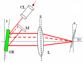
Figure 2. The modified low power RSOD. M, double pass mirror; GR, diffraction grating; L, lens; α, β and γ, tilting angles of the scanning mirror, the lens and the grating, respectively; Δx, pivoting point lateral offset
The edge of the lens in this case works as an additional optic element, prism, which helps to compensate the appeared dispersion[12]. After reflection from the scanning mirror the light comes back through the centre of the lens, then to the grating and to the double pass mirror (M). On the way back the dispersion is recombined the same way as described before[5,13]. Since the beam moves over almost flat surface of the lens, this geometry enables to achieve very small distortions of the optical pathlength, efficient recoupling of the light to the RA fibre tip and application of a lens (L) with short focal length. Application of the lens with shorter focal length is important for the efficient recouping of the broadband light, since its divergence is higher than the divergence of a narrowband laser. It turned to be also important from experimental point of view to consider the thickness of the lens (L), which is up to 20-29% of its focal length, Lf. 60 mm focal length gives up to 8 mm linear depth scan in a sample, a lens with Lf = 50 mm gives up to 5 mm, and lens with Lf = 45 mm up to 3 mm according to the group delay formula[5,13]. If the beams are in the different optical planes the double pass mirror M could be moved toward and underneath the incident beam. Such tuning was realised in the described experiments and this gave the possibility to utilise dynamic depth-related change of RA intensity and shape during the scanning period. To tune the system to the lowest envelope dispersion mode, the angle and the position of the lens were changed, instead of change of the position of grating[4,12,13]. This approach gives the possibility to compensate dispersion and easily achieve theoretical axial resolution, Lax ≈ 0.44λ2/Δλ in the free space, and considering refractive index of the sample, n, Laxs ≈ 0.44λ2/(Δλn)
The described modifications of the Fourier-domain rapid scanning optical delay line make it easy to compensate dispersion and chirp of the coherence envelope, increase scanning depth without compromising the carrier frequency, fo, stability, and to obtain more narrow spectrum of it[5],
(1)
Here α is the angle of the scanning RA mirror, Δx – the scanning mirror offset.
Attenuating reference arm power in LCI with a stable SLD source gives considerable, up to 34 dB, S/N ratio improvement[14]. In addition, since the described RSOD enables to recombine broadband light more efficiently, it is possible to use low power, low noise SLD which itself reduces source noise and incoherent broadband light[2,15], Iin, in the detected interference signal intensity, I,
(2)
Here Ir and Is reference and sample arm light intensity, respectively. The incoherent component, Iin, appears as the phase noise[2] in coherence-gated systems in contrast to the heterodyne detection in quasielastic light scattering systems with application of a narrowband source with Δλ ~ 0.1 - 1.0 nm.
The employed pivoting point offset, Δx, also corresponds to the width, Δf, of the carrier spectrum in the Fourier transform of the autocorrelation function which should be similar to the width of the bandpass filter[5],
(3)
Here d is the pitch of the grating.
Introduction of the carrier in the LCI[2] gave possibility to tune off low frequency 1/f noise and at the same time keep the carrier within the range of hundreds of kilohertz. Keeping the carrier fo < 100 kHz gives the possibility to avoid increasing at higher frequencies white noise and to use narrow bandpass filters of about 5 - 15 kHz. Also, there is no need to use high frequency electronics. Special care should be taken setting the scanning mirror offset, Δx. Bigger offset gives bigger values of the carrier, more than 100 kHz. Small offset will lead to partial overlapping of the broadband spectrum in the Fourier plane (1, 3).
Signal processing has been performed digitally offline with a standard demodulation algorithm, which was applied earlier[9,16]. This algorithm utilises short-time Fourier transform (STFT) with the sliding Hanning window. The processing takes from one to two seconds using 2.4 GHz, Intel Pentium IV processor. Utilising C++ language it is possible to design dedicated software and perform real time signal processing with up to 1 kHz of RA scanning frequency[8]. Using RA scanning frequency of about 80 - 100 Hz it is obviously possible to perform such processing with one to two frames per second, 300 - 500 lines per frame, what is enough for real time imaging and visual feedback.

3. Results and Discussion

The described modifications of the time domain OCT system, for the first time, gave the possibility to obtain images of a macro blood vessel (~1 mm in diameter) underneath the native human skin with transcutaneous depth of about 1.5 – 1.6 mm[9]. The images have been taken close to a Y-junction of blood vessels considering possibility of further investigation of blood flow with complex geometry [16-18] in vivo.
The described system also gives possibility to use two wavelengths close to 1.3 μm and 1.5 μm simultaneously. Separation of the images could be performed in the processing algorithm, since the two wavelengths will give the two different carriers (1, 3). Figure 3 shows the images of a human finger tip using 1.3 μm SLD (λ=1298 nm, Δλ=52 nm) and 1.5 μm SLD (λ=1482 nm, Δλ=60 nm). Note, the OCT image using 1.5 μm SLD and RSOD was obtained by us for the first time[19].
Transcutaneous probing depth of the light at λ = 1.5 μm is approximately twice less to compare with more commonly used for the skin study wavelength 1.3 μm [6]. Therefore we choose standard for this cases 1.3 μm source. All further results are obtained using SLD with λ=1298 nm, Δλ=52 nm.
Figure 4 shows two blood vessels of a human subcutaneous Y-junction close to the junction with considerably low resolution but with the increased probing depth up to ~1.5 mm. Refractive index of the tissue, n=1.4, is used in all cases.
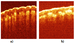
Figure 3. OCT images of human finger tip in vivo, (a) obtained using SLD with λ=1298 nm, Δλ=52 nm; (b) using SLD with λ=1482 nm, Δλ=60 nm. Size of the images is 2x2 mm2
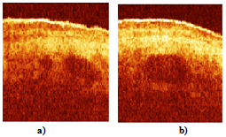
Figure 4. Subcutaneous macro blood vessels of a human finger in vivo, (a) close to Y-junction; and (b) at the junction. Size of the images is 2x2 mm2
Figure 5a) shows another blood vessel underneath the native skin of a human finger. Frequency of the reference arm scanner is set to the value of 80 Hz. The quality at the deeper layers starts to degrade after increasing the scanning frequency and only upper layers of the skin could be observed after 100 Hz even if the carrier is kept within the range of the bandpass filter.
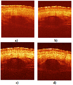
Figure 5. Subcutaneous blood vessel of a human knuckle joint in vivo. (a) fist image; (b) 15 min after application of the optical clearing liquid; (c) after raster scan and averaging over four consecutive A-scans; (d) 20 min after application of the optical clearing liquid. Stratum corneum, epidermis, dermis, fascia and blood vessel are clearly seen in all images. Reticular dermis is not clearly distinguishable. Size of the images is 2x2 mm2
To increase the resolution and the penetration depth, glycerol was utilised as an optical clearing liquid[11]. It was topically applied onto the skin where the blood vessels (veins) have been barely seen by the naked eye. Figure 5b) shows the image of the same blood vessel after 15 min from the beginning of the optical clearing. To reduce shot noise, phase noise from the incoherent detection and speckle noise which appears due to high spatial coherence of the source we perform averaging over 2 to 4 A-scans while changing the angle of the scanner in the sample arm. The scanner moves 2 to 4 times slower in this case ensuring raster scanning and corresponding raster averaging over 2 to 4 lines within one pixel size. In addition to that 0.1 - 0.3 mm pivoting point offset of the sample arm scanning mirror was introduced to perform movement of the beam across each pixel of the image. The raster averaging elongates acquisition time proportionally up to 2 to 3 sec but additionally increases signal-to-noise ratio by 4 - 8 dB. This approach enables to reduce speckle noise, increase contrast and better visualise deeper layers of the skin, Figure 5c). A distinct structural signal backscattered from blood was possible to detect as well. It appears inside the blood vessel after one minute of hand exercise only, Figure 5b,c). The achieved RA phase stability between consecutive A-scans was about 10 - 20 %. Therefore it was not possible to detect reliable phase shift between consecutive interferograms and extract velocity information of the blood flow in the shown vessels. Nevertheless, intensity signal of the structural image from faster moving blood corpuscles becomes stronger due to more scattering events over probing volume for the chosen detection time.
Figure 5d) shows the same vessel after the 20 min from the beginning of the process of optical clearing. The upper surface structures are less distinguishable, although the structures at the depth of about 1.5 - 1.6 mm are better resolved. The shape of the vessel appears to be more rounded. This phenomenon is important and could be explained by the change of average refractive index of the tissues around the lumen of the vessel.
Figure 6 shows images of human palm with much more dense skin than one of a finger. These images were obtained before (a) and after (b) 15 min application of the optical clearing liquid. No averaging has been performed in this case, although the circled macro structures appear after the cleaning only and surely are the blood vessels.
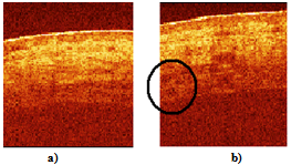
Figure 6. OCT images of a human palm in vivo, (a) before optical clearing; (b) 15 min after the optical clearing. The circled structures are the blood vessels. Size of the images is 2x2 mm2
Separate A-scan calculations reviled that the upper layers are resolved with the accuracy of about 12 - 15 micron, which corresponds to the axial resolution Laxs. The lower layers are resolved with the resolution of 30 - 50 microns only. This strongly suggests that the multiply scattered photons which are still coherent to the reference signal are detected from the structures deeper than 0.8 -1.0 mm[10]. Since the spatial resolution gradually decays the bandwidth of the source could be correspondingly chosen. This we presume will additionally increase the coherence probing depth while still compromising the lateral and depth resolution.

4. Conclusions

The modified low power RSOD in the reference arm of the scanning interferometer enables to apply 1.3 μm wavelength simultaneously with 1.5 μm. Application of any other wavelength in between or close to these two is also possible. This enables to make rapid differential and spectral OCT imaging for two or several wavelengths. In addition the modified RSOD is quite small ~ 11x7x5 cm3, what is important from practical point of view. Using this experimental approach for the first time we have demonstrated subcutaneous macro (~0.2 - 1 mm) blood vessels underneath the native human skin by detection of singly and multiply scattered photons. The described set-up enables to increase transcutaneous coherence probing depth up to 1.5 - 1.6 mm and to resolve deeper tissue structures while compromising spatial resolution. Coherent detection of least scattered photons demonstrates transitional coherence-gating mode between single scattered and diffuse photons[20]. Since ballistic photons could be discriminated from the diffuse ones at the depth of about 20 - 25 MFP[10,21] and having in mind the reduced scattering coefficient of biological tissue ~ 1 mm-1, it seems to be reasonable to assume further increase of transcutaneous coherence probing depth to the values of about 2 - 2.5 mm.
Doppler OCT technique[6,7] was not applicable in this case due to low phase stability of the consecutive A-scans. In addition, all experiments have been performed when incident light was perpendicular to the surface of the skin. Will it be possible to extract valuable velocity information in such transitional coherence-gated mode to study flows with complex geometry[16-18] in human subcutaneous junction of blood vessels is still a question to solve. Applying optical circulator (Faraday rotator) instead of the first 1x2 fibre splitter it is possible additionally reduce the source power by the factor of two and eliminate the signal reflected back into the source[15].

ACKNOWLEDGEMENTS

This research was supported by The Engineering and Physical Sciences Research Council (EPSRC) grant GR/ R06816/02.

References

[1]  A.F.Fercher, W.Drexler, C.K.Hitzenberger, T.Lasser, 2003, Optical coherence tomography - principles and applications, Rep. Prog. Phys., 66, 239
[2]  R.C.Youngquist, S.Carr, D.E.N.Davies, 1987, Optical coherence-domain reflectometry: a new optical evaluation technique, Opt. Lett., 12, 158
[3]  K.F.Kwong, D.Yankelevich, K.C.Chu, J.P.Heritage, A. Dienes, 1993, 400-Hz mechanical scanning optical delay line, Opt. Lett., 18, 558
[4]  G.J.Tearney, B.E.Bouma, J.G.Fujimoto High-speed phase- and group-delay scanning with a grating-based phase control delay line, Opt. Lett., 22, 1811
[5]  A.Rollins, M.Kulkarni, S.Yazdanfar, R.Ung-arunyawee, J.Izatt, 1998, In vivo video rate optical coherence tomography, Opt. Exp., 3, 219
[6]  Y.Zhao, Z.Chen, C.Saxer, S.Xiang, J.F.de Boer, J.S.Nelson, 2000, Phase-resolved optical coherence tomography and optical Doppler tomography for imaging blood flow in human skin with fast scanning speed and high velocity sensitivity, Opt. Lett., 25, 114
[7]  M.C. Pierce, B.H.Park, B.Cense, J.F.de Boer, 2002, Simultaneous intensity, birefringence, and flow measurements with high-speed fiber-based optical coherence tomography, Opt. Lett., 27, 1534
[8]  B.H.Park, M.D.Pierce, B.Cense, J.F.de Boer, 2003, Real-time multi-functional optical coherence tomography, Opt. Exp., 11, 782
[9]  S.G.Proskurin, Y.He, R.K.Wang, 2004, Investigation of flows with complex geometry using coherence domain tomography, Proc. SPIE, 5330, 38
[10]  K.K.Bizheva, A.M.Siegel, D.A.Boas, 1998, Path-length- resolved dynamic light scattering in highly scattering random media: The transition to diffusing wave spectroscopy, Phys. Rev. E, 58, 7664
[11]  A.N.Bashkatov, E.A.Genina, I.V.Korovina, V.I.Kochubey, Yu.P.Sinichkin, V.V.Tuchin, 2000, In vivo and in vitro study of control of rat skin optical properties by acting of osmotical liquid, Proc. SPIE, 4224, 300
[12]  E.D.J.Smith, A.V.Zvyagin, D.D.Sampson, 2002, Real-time dispersion compensation in scanning interferometry, Opt. Lett. 27, 1998
[13]  A.V.Zvyagin, E.D.J.Smith, D.D.Sampson, 2003, Delay and dispersion characteristics of a frequency-domain optical delay line for scanning interferometry, JOSA A, 20, 333
[14]  W.V.Sorin, D.M.Baney, 1992, A simple intensity noise reduction technique for optical low-coherence reflectometry, IEEE Photon. Techn. Lett., 4, 1404
[15]  A.M.Rollins, J.A.Izatt, 1999, Optimal interferometer designs for optical coherence tomography, Opt Lett., 24, 1484
[16]  S.G.Proskurin, I.A.Sokolova, R.K.Wang, 2003, Imaging of non-parabolic velocity profiles in converging flow with optical coherence tomography, Phys. Med. Biol., 48, 2907
[17]  S.G.Proskurin, Y.He, R.K.Wang, 2004, Doppler optical coherence imaging of converging flow, Phys. Med. Biol., 49, 1265
[18]  M.Bonesi, S.G.Proskurin, I.V.Meglinski, 2010, Imaging of subcutaneous blood vessels and flow velocity profiles by Optical Coherence Tomography, Laser Physics, 20, 891
[19]  S.G.Proskurin, R.K.Wang, 2004, Human subcutaneous blood vessels visualization by increasing coherence probing depth, Quantum Electronics, 34, 1157
[20]  S.G.Proskurin, 2011Using late arriving photons for diffuse optical tomography of biological objects, Quantum Electronics, 41, 402
[21]  M.R.Hee, J.A.Izatt, J.M.Jacobson, J.G.Fujimoto, E.A. Swanson, 1993, Femtosecond transilluminaton optical coherence tomography, Opt. Lett., 18, 950