-
Paper Information
- Paper Submission
-
Journal Information
- About This Journal
- Editorial Board
- Current Issue
- Archive
- Author Guidelines
- Contact Us
American Journal of Signal Processing
p-ISSN: 2165-9354 e-ISSN: 2165-9362
2021; 11(1): 1-7
doi:10.5923/j.ajsp.20211101.01
Received: Jan. 26, 2021; Accepted: Mar. 1, 2021; Published: Mar. 15, 2021

Collage Quality of Two Different Plates by Using Ultrasonic
 Abstract
 Reference
 Full-Text PDF
 Full-text HTML
Brahim Irissi 1, El Houssaine Ouacha 1, 2, Bouazza Faiz 1, Hicham Banouni 1
1Laboratory of Metrology and Information Processing, Ibn Zohr University, Faculty of Sciences, Agadir, Morocco
2Higher School of Education and Training, Ibn Zohr University (ESEFA – UIZ), Agadir, Morocco
Correspondence to: El Houssaine Ouacha , Laboratory of Metrology and Information Processing, Ibn Zohr University, Faculty of Sciences, Agadir, Morocco.
| Email: |  |
Copyright © 2021 The Author(s). Published by Scientific & Academic Publishing.
This work is licensed under the Creative Commons Attribution International License (CC BY).
http://creativecommons.org/licenses/by/4.0/

The collage quality of the plates is very important and decisive in the industry and more particularly in that of aeronautics. As much as the safety of the structures with respect to the constraints to which they are subjected is decisive in the industry. The control of the mechanical state of the bonded structures in service or not is essential. For this purpose, the control of the reflection coefficient of an ultrasonic beam on a bonded structure makes it possible to study theoretically and then experimentally the mechanical behavior. The PILARSKI model is applied in this work and will clarify the quality of the collage of two plates of different natures. Indeed, the amplitude variation of the reflection coefficient depends on the quality of the collage.
Keywords: Ultrasonic, Non-destructive testing, Reflection coefficient, Collage
Cite this paper: Brahim Irissi , El Houssaine Ouacha , Bouazza Faiz , Hicham Banouni , Collage Quality of Two Different Plates by Using Ultrasonic, American Journal of Signal Processing, Vol. 11 No. 1, 2021, pp. 1-7. doi: 10.5923/j.ajsp.20211101.01.
Article Outline
1. Introduction
- When two solid media are coupled together with a layer of glue, the mechanical behavior of the structure can be studied from the tracking of the reflection coefficient or transmission of an ultrasonic beam. Indeed, the amplitude variations of these coefficients as a function of the frequency depend strongly on the nature of the coupling. The choice of boundary conditions that must describe the effects of coupling is very important in the theoretical and experimental approach of this problem.Constraints at the collage joint have a direct influence on the behavior of the layers [1] [2]. As a result, an estimate of the allowable stress levels by the in-service structure is necessary to reduce the probability of failure.The evaluation of residual stresses is the subject of an increasing demand of the metal trades, thus favoring the development of various methods such as X-ray diffraction, incremental drilling and more recently the ultrasonic method and noise Barkhausen [20]. Numerous studies have clearly shown that there is no universal or absolute method that gives complete satisfaction in the field of control of mechanical components in service [18]. Each method has its area of use and validity. The choice of the method used depends on the material, the geometry of the piece, the surface condition, and the nature of the glue as well as the accuracy of the desired result.In this study, we will focus on the ultrasonic measurement method. The latter, despite its sensitivity to the effects of microstructure and operating conditions, remains potentially one of the most promising [3]. It is non-destructive and allows to control the quality of a collage of a Plexiglas plate and a glass plate. This method is based on the behavior of the resonance frequencies of the structure of the two plates joined by a layer of glue. The cost of its equipment is the main advantage that explains and encourages its development. We will calculate theoretically the frequency variations of the reflection coefficients in the case of a collage of two plates using the conditions of PILARSKI [13]. This author supposed that one could pass continuously a perfect contact (continuity of displacements and normal and tangential stresses) to a sliding contact (continuity of the normal and tangential stress, continuity of the normal displacement and discontinuity of the tangential displacement) by postulating that the tangential stress is proportional to the difference of displacements on both sides of the interface. We will also present the experimental results based on the measurement of the reflection coefficients of the Plexiglas / Glue / Glass structure for different collage qualities.
2. Presentation of the Assembly of the Experimental Technique: Monostatic Method
- In this arrangement, measurements are made by an ultrasonic transducer of the 5 MHz center frequency. The transducer used operates alternately as transmitter and receiver. The pulse generator electrically excites the transducer. The latter excites, under normal incidence, the Plexiglas / Glue / Glass structure. The backscattered signal is picked up by the same transducer. The signal passes through the same cable as the transmission signal and arrives at the T / R connector from which the transmission signal was sent. The received signal is visualized by connecting the output signal connector to the input of a picoscope (350 MHz) via a coaxial cable. The latter is synchronized by the generator thanks to a coaxial cable connecting between its connector (EXTERNAL TRINGER) and the entrance (AUX IN Connector) picoscope. The ultrasonic signal is finally visualized on a laptop connected to the picoscope by a USB cable. Figure 1 below shows the diagram of the experimental setup used in this work to measure the reflection coefficient of the Plexiglas / Glue / Glass structure.
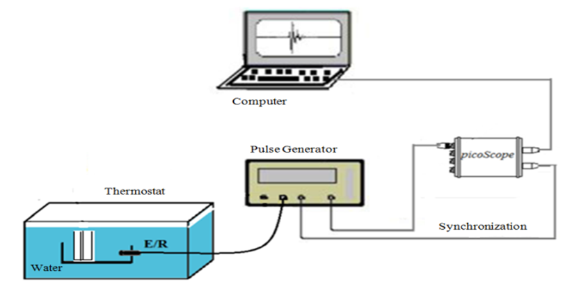 | Figure 1. Diagram of the assembly of the monostatic method |
3. Materials and Methodology
- All paragraphs must be indented. All paragraphs must be justified alignment. With justified alignment, both sides of the paragraph are straight.
3.1. Sample Preparation
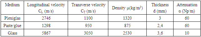
- The preparation of the samples of the Plexiglas / Glue / Glass structures to be characterized is very important and this step is decisive. To create the sample well, the same thicknesses of the adhesive must be kept between Plexiglas plates and glass. The thicknesses of the Plexiglas, the adhesive layer and the glass of the Plexiglas / Glue / Glass structure are respectively [3 mm / 2.4 mm / 3.6 mm].The elastic parameters of Plexiglas, glass and glue are grouped in the table below [6].
|
3.2. Theoretical Study
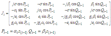
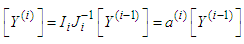
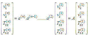
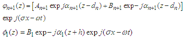
- In this work, we will resume the work of BREKHOVSKIKH [7] and other authors [8] [9] on the diffusion of a planar stratified medium composed of n solid layers. There are two computational methods. The first one consists in writing the continuity equations in terms of potentials at each interface of the structure, and then solving linear systems of p equations with unknown p [10]. The number p increases with the number of layers. This method is expensive in terms of calculation (for n layers, 4n+2 equations are needed). The second method, presented in this paper, is based on recurrence formulas linking the wave amplitudes in two neighboring layers "Fig. 2". It is assumed that a harmonic plane wave arrives in the milieu n+1 on the multilayer structure at an angle of incidence θn+1. The wave vector of the incident wave is assumed to be contained in the xOz plane, which makes the problem two-dimensional. Each layer i of the multilayer medium is defined by its density ρi, its LAME coefficients λi and μi longitudinal velocities cLi and transversal cTi and its thickness di. The layers are assumed to be infinitely extended in the xOy plane. The origin of the direct orthonormal coordinates system (O, x, y, z) is chosen on the interface between the nth layer and the (n-1)th layer.
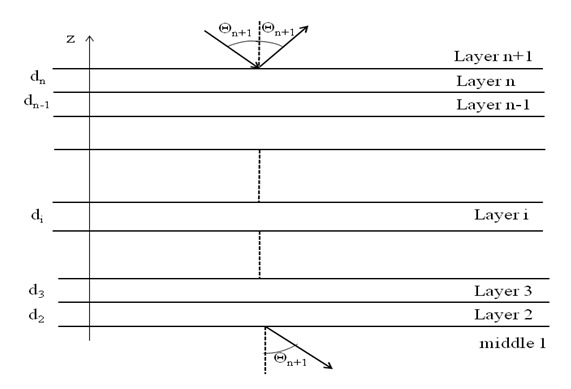 | Figure 2. Reflection and transmission through a plane laminated medium composed of (n - 1) solid layers. Geometry of the problem |
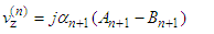
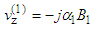
 . Velocity and movement are linked simply by the relation
  The velocities and stresses in each layer i can be expressed in terms of the following potentials:
 | (1) |
 | (2) |
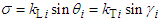 is the tangential component of the wave vectors of the waves propagating in each layer, according to the law of SNELL-DESCARTES.
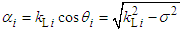 is the normal component of the wave vector of the longitudinal wave in the ith layer.
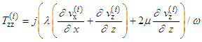
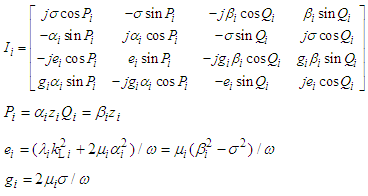
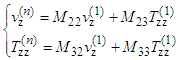
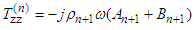
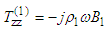
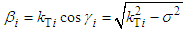 is the normal component of the wave vector of the transverse wave in the ith layer.θi, γi are respectively the angles that the directions of propagation of the longitudinal and transverse waves make with respect to the normal to the layer i.The tangential and normal components of velocity and stress in layer i are written as follows [11]:
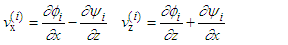 | (3) |
 | (4) |
 | (5) |
 | (6) |
 | (7) |
 | (8) |
 | (9) |
 | (10) |
 | (11) |
 | (12) |
 | (13) |
 | (14) |
 | (15) |
 | (16) |
 | (17) |
 | (18) |
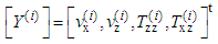
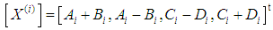
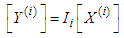
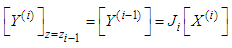
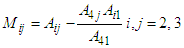
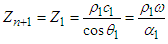
 where
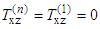
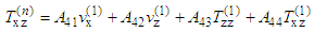
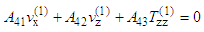
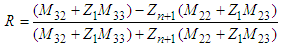
where  The reflection coefficients of the solid multilayer are such that:
 | (19) |
 | (20) |
 | (21) |
 | (22) |
 | (23) |
 | (24) |
3.3. Experimental Study
- In this work, the Plexiglas/Glue/Glass structure, consisting of a Plexiglas plate, a glass plate and a layer of glue is emerged in water and insulated by an ultrasonic pulse. The method implemented consists in measuring the reflex coefficient of the Plexiglas/Glue/Glass structure. The geometry of the problem is schematized in figure 3.
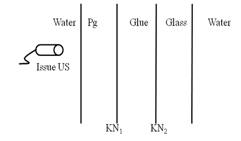 | Figure 3. Geometry of the problem |
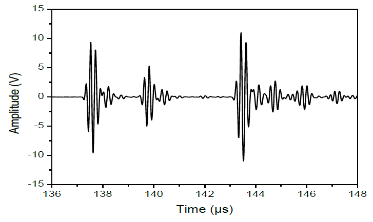 | Figure 4. Signal backscattered by the Plexiglas/Glued/Glass structure Emission on the Plexiglas side (Good collage) |
 where A and A' are the spectral amplitudes of the signals reflected from the Pg/Glass structure and the specular respectively. R' corresponds to the reflection coefficient of the water/plexiglas interface [11] [19]:
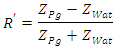 with
with 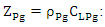 Acoustic impedance of Plexiglas.
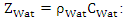 Acoustic impedance of water.
4. Experimental Results and Discussions
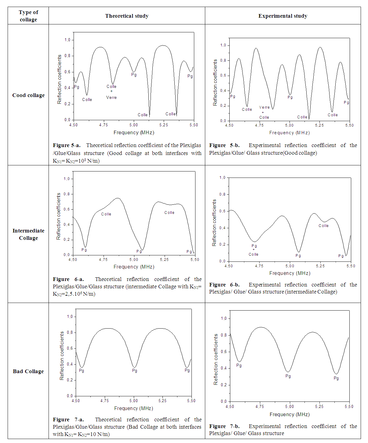
- The objective is to compare theoretical results with experimental results. The theoretical and experimental results of reflection coefficients are presented in the 4.5 MHz and 5.5 MHz frequency domain. For the experimental part, a wide band transducer with a center frequency of 5MHz was used. The incident ultrasonic beam is sent from the Plexiglas side and normal to its surface. The transverse velocity has no influence. The quality of the bond is checked by measuring the reflection coefficient. The reflection coefficient is represented as a function of frequency at normal incidence for the Pg/Glue/Glass structure and the only parameter that changes is the quality of the glue. The minima in the reflection coefficients correspond to the resonance frequencies of the structure. These resonance frequencies are relative to the three materials: Plexiglas, glue and glass. The modules of the theoretical and experimental reflection coefficient by the structure are shown in the following figures. The study makes it possible to isolate and identify the resonance frequencies of the structure.Figures 5-a and 5-b represent the reflection coefficient (theoretical and experimental study) as a function of frequency for good collage at the two interfaces (Plexiglas/Glue and Glue/Glass). Each interface is characterized by the PILARSKI coefficient [13] [14] KN1 and KN2 which are, in the case of good collage, very large. In this frequency domain there are four longitudinal modes relative to the adhesive layer, three longitudinal modes relative to the Plexiglas plate and only one longitudinal mode relative to the glass plate.The representations of the theoretical (Figure 5-a) and experimental (Figure 5-b) reflection coefficients in the case of the Plexiglas/Glue/Glass structure show that the modes relative to the glue layer and the glass plate are relatively very deep compared to the other qualities of the glue as will be seen for the other qualities of the glue.In the case of an intermediate collage the theoretical and experimental reflection coefficients are shown in Figure 6-a and Figure 6-b. Each interface is characterized by the PILARSKI coefficients [13] [14] KN1 and KN2 equal to 2.5 106N/m. The disappearance of the mode relative to the glass plate is noted. However, the existence of the modes relative to the Plexiglas plate and to the adhesive layer is still noticeable. However, the depth of the modes relative to the glue layer for this case is not great compared to that of good gluing [17]. Due to the low ultrasonic amplitude at the Plexiglas/glue interface on the one hand and the decrease of the ultrasonic amplitude at the glue/glass interface on the other hand. The low ultrasonic transmission at both interfaces causes the glass mode to disappear. In the case of poor collage the theoretical and experimental reflection coefficients are shown in Figure 7-a and Figure 7-b. For poor collage, each interface is characterized by the PILARSKI coefficients [13] [14] KN1 and KN2 equal to 10N/m. For this glueing quality, we notice in figures 7-a and 7-b a disappearance of the modes relative to the glue and the glass. This disappearance of the glue and glass modes is due to poor collage at the two interfaces (Plexiglas/Glue and Glue/Glass) [15]. Poor collage decreases the amplitude of the ultrasonic wave on the other side of the interface. The low amplitudes do not allow the ultrasound to go back and forth either in the adhesive layer or in the glass layer.
 | Figures 5-7 |
5. Conclusions
- For quality control of the collage of the structure (Plexiglas/glue/glass), a non-destructive ultrasonic pulse- echo technique has been proposed. This technique is based on the control of the ultrasonic reflection coefficient. The amplitude of the reflection coefficient of the structure immersed in water varies as a function of the frequency and depends on the quality of the collage. The experimental and theoretical results of the amplitude of the reflection coefficient are concordant for the three types of collage. The quality of the collage can therefore be determined easily and quickly by checking the reflection coefficient. The study is based on the control of resonance modes and their amplitudes. The analysis of the experimental and theoretical results shows that it is possible to control the collage quality of certain structures during the industrial production process or after their use. The use of ultrasonic techniques offers a reliable, non-destructive and instantaneous means of control.