G. Viswanadh Raviteja1, K. Sridevi1, V. Malleswara Rao1, A. Jhansi Rani2
1Department of ECE, GITAM University, Visakhapatnam, India
2Department of ECE, VR Siddhartha Engineering College, Vijayawada, India
Correspondence to: G. Viswanadh Raviteja, Department of ECE, GITAM University, Visakhapatnam, India.
| Email: |  |
Copyright © 2016 Scientific & Academic Publishing. All Rights Reserved.
This work is licensed under the Creative Commons Attribution International License (CC BY).
http://creativecommons.org/licenses/by/4.0/

Abstract
Uniform circular arrays are commonly used geometrical arrangements in smart antenna systems. These arrangements of antennas radiate their own individual beam patterns adaptively producing different radiation properties for different geometrical arrangements. The array factor determines the overall radiation pattern. The radiation patterns for uniform circular arrays and planar uniform circular arrays are presented in this paper using Normalized fractional Least Mean Squares as the weighting scheme. Results obtained show that planar uniform circular array (4:8) using Normalized Fractional Least Mean Squares algorithm is more suitable for high-end applications as its side lobe levels are greatly reduced compared to the other geometry.
Keywords:
NFLMS, Planar uniform circular array, Smart antennas, Uniform circular arrays
Cite this paper: G. Viswanadh Raviteja, K. Sridevi, V. Malleswara Rao, A. Jhansi Rani, Synthesis of Adaptive Uniform Circular Array Using Normalized Fractional Least Mean Squares Algorithm, American Journal of Signal Processing, Vol. 6 No. 1, 2016, pp. 14-18. doi: 10.5923/j.ajsp.20160601.02.
1. Introduction
Demand for mobile technology saw a substantial growth in the field of wireless communications over the last decade. Increase in larger coverage area, channel capacity and higher wireless traffic proved to be very essential. The implementation of adaptive or smart antennas became necessary. A smart antenna adaptively steers its main beam in the desired direction and also placing nulls in the undesired direction simultaneously, increasing the system capacity. The use of digital signal processor is the one which makes the smart antennas to be really smart [1]. More degree of freedom results when multiple antenna element sources are taken which in turn permits more control over radiation characteristics of antenna [5].The antenna array projects a directional beam to allow communication in a required direction. Radiation pattern is always determined by taking into account of the geometrical arrangement made [3]. When an array composed of several antenna elements are taken the overall radiation pattern change. One disadvantage with linear arrays is that the omnidirectional pattern will be affected by the corners and also makes it difficult to steer the beam through 360° [2]. This is achieved by the use of circular arrays. Coverage of 360 degrees in the azimuthal plane is achieved greatly with the use of uniform circular arrays (UCA). The circular arrays have an advantage that it doesn’t have the edge elements which makes it possible to electronically rotate. Also by the use of circular arrays the effect of mutual coupling can be compensated as the array excitation can be split up into several symmetrical spatial components [7]. Steering capability of the array can be increased by the use of planar arrangement with center element.Several commonly used algorithms are available to calculate the excitations namely Least Mean Square (LMS), Recursive Least Mean Squares (RLS), Particle Swarm optimization (PSO). The algorithm Normalized Fractional Least Mean Squares (NFLMS) described is used as optimization algorithm. Derived from algorithms Least Mean Squares (LMS), Fractional Least Mean Squares (FLMS) and Normalized Least Mean Squares (NLMS), the NFLMS provides better convergence [6]. The various adjustments and modifications in the step input and weight vector of standard LMS led to the design of FLMS. To improve the performance of the algorithm, one effective way is normalization. This led to the design of NLMS [8], [9]. In this paper, 2 different types of UCA radiation properties are studied. Out of the four sections divided in the paper. Section 2 Deals with the array geometry and the algorithm used for beam forming. Section 3 Deals with the simulation results. Section 4 finally concludes the paper.
2. Methodology
Historically, to synthesize far field radiation pattern, antenna arrays are used. Linear or planar antenna arrays are used for this purpose. Linear arrays come into use when only horizontal plane is to be scanned. But, when it comes to scanning 3600 without any distortion in the radiation pattern, circular arrays are used. Because of the virtue of its symmetry, circular array antennas are widely used. A uniform performance regardless of the angle of arrival is seen with UCA. One of the interesting features of circular array is that the radiation impedance of the element will be altered by the mutual coupling [4]. But, the impedance of all elements will be changed or modified by only small extent because the symmetrical configuration of the circular arrays. Hence, in the far field only the amplitude of harmonic will be modified. Therefore the mutual coupling effect can be compensated by the measurement of harmonic amplitude in far field and then by adjusting the current harmonic amplitude on the antenna array to acquire the required harmonic of far field [2].
2.1. Array Configuration
In the proposed paper, two circular array configurations are determined using 12 isotropic elements for each configuration. The configurations are Uniform circular array (UCA (12)), planar uniform circular array (PUCA (4:8)). There are three categories of planar arrangements; square, circular and rectangular. The circular arrays do not possess edge elements among the given three categories, which makes it possible for the beam pattern of circular array to be electronically rotated [3]. The following figures represent the array geometry for the above stated two configurations. Firstly, the uniform circular array geometry is represented. 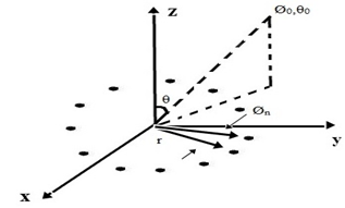 | Figure 1. The Uniform Circular Array - UCA (12) |
The array factor for the UCA (12) is given by (1),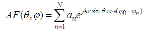 | (1) |
Where an and Φn are the excitation and azimuthal angle of the nth element. For this paper r, is set 1.96λ and separation between the elements is 0.62λ.The configuration for PUCA is given in the Figure 2 [5]The array factor for PUCA (4:8) is given by (2) [3], 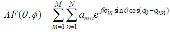 | (2) |
Where amn and Ømn are the excitation and the azimuth angle of nth element in mth ring. The radius of outer ring r1, set to 1.96λ and radius of inner ring r2 is set to 1.23. N is the total number of Nth elements in Mth rings.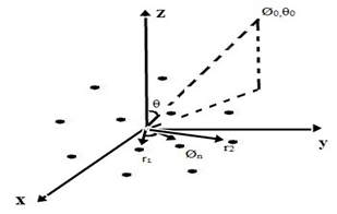 | Figure 2. The Planar Uniform Circular Array - PUCA (4:8) |
2.2. Normalized Fractional Least Mean Squares Algorithm (NFLMS)
The study of Stochastic-gradient algorithms led to the development of adaptive algorithms. Using some approximations and suitable changes in the gradient vectors, these methods are carried out. Different approximations lead to different algorithms with variations in complexity and performance properties. Stochastic gradient algorithms basically serve two purposes. The necessity to know the signal statistics for steepest descent implementation is very much essential, but is rarely available in practice. Also tracking mechanisms that enable to track variation in signal statistics are possessed by these methods. These two combined properties are the main reason behind the rapid growth and widespread use of stochastic gradient methods. It is also because of this reason; we often describe adaptive filters as “smart systems” [6]. Algorithms such as LMS, RLS, etc., fall under this category. The adaptive features of smart antenna systems attracted wide interest in the communication field over the last decade [2].Several algorithms have been proposed over the years to optimize the excitation parameters; both phase and amplitude of the antenna arrays. The algorithms such as LMS, RLS and CME are used for the purpose of excitation.A simplification of the steepest descent method, LMS algorithm [7] is most widely used algorithm for excitation. The fractional LMS in addition to the first derivative has a fractional derivative. After simplifying the derivatives we have the final weight update relation for FLMS given in the following way (3), 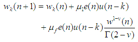 | (3) |
Where ‘w’ is the weight vector, ‘µ’ is the step-size, ‘uf’ is the fractional step-size and ‘v’ is the fractional derivation order and Γ (.) is the gamma function.The LMS has a disadvantage of gradient noise amplification problem. Normalized LMS is used in order to overcome the problem. The main difference between the latter and former is the way in which weights are updated [11]. The weight update relation for NLMS is given by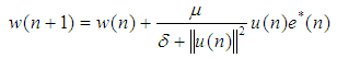 | (4) |
Where ║u(n)║2 represent the power of input vector and δ > 0.Here in this paper an improved version of conventional LMS algorithm called Normalized fractional least mean square algorithm (NFLMS) is used [6].The normalized version of the LMS algorithm has better performance than the conventional LMS filters. Also the NFLMS has faster convergence than the LMS algorithm. The weight update formula for this algorithm is given by (5) [6]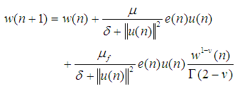 | (5) |
3. Results and Discussion
In this section, a comparison is made for the described array configurations based on their radiation properties and side lobe levels. As stated earlier, NFLMS algorithm is used as weighting scheme to steer the main beam towards desired direction and placing nulls at interference signals. The parameters for the NFLMS are taken as µ = 0.5 for step unit and µf = 0.045 for the fractional step input. The fractional derivative order v = 0.2. The simulations are carried using MATLAB.
3.1. Radiation Pattern
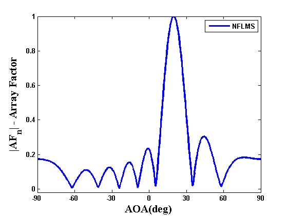
The behaviour of the mentioned array geometries is studied. Firstly, results are computed basing on the side lobe levels of UCA and PUCA. From the simulations, it is learnt that side lobe levels (SLL) for Planar Uniform Circular Array is considerably reduced when compared to the Uniform Circular Array. The figures are plotted in the following way as given below.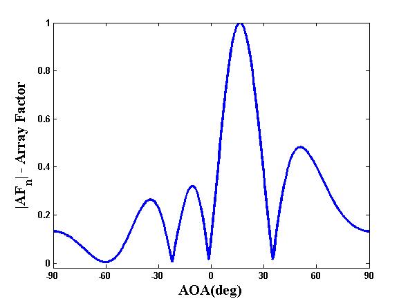 | Figure 3. Uniform Circular Array (UCA (12)) with desired angle 200 |
 | Figure 4. Planar Uniform Circular Array (PUCA 4:8)) with desired angle 20° |
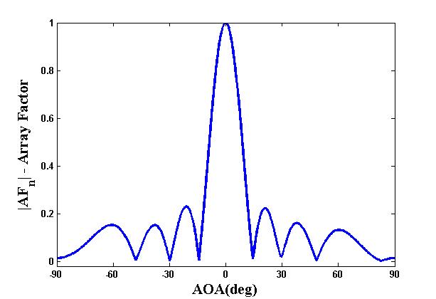 | Figure 5. Planar Uniform Circular Array (PUCA 4:8)) with desired angle 0° |
The array geometry behaviour in adapting to the interference signals is based on the following scenario; a desired signal with two interfering signals. The desired signal is placed at a 30°, the first interference signal at -30°, and the second interference at 60°. The number of elements N = 12. A comparison for the given algorithm is also made with FLMS and NLMS algorithms.The resulting plot for radiation pattern of Uniform circular array using FLMS, NLMS and NFLMS is shown in Figure 6.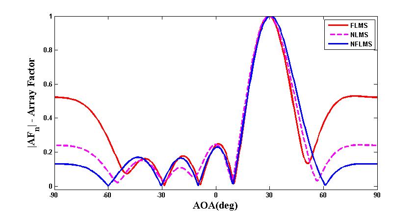 | Figure 6. Radiation Pattern for Uniform Circular Array (UCA (12)) |
The radiation pattern plot for planar uniform circular array using FLMS, NLMS and NFLMS is shown in Figure 7.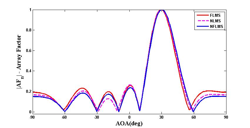 | Figure 7. Radiation Pattern for Planar Uniform Circular Array (PUCA (4:8)) |
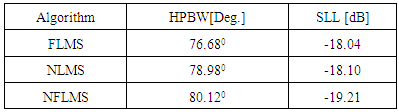
For the PUCA configuration also, the desired signal is placed at 30°, the first interference at -30°, the second interference at 60°. The number of elements taken are N = 12.The results obtained show that side lobes are considerably reduced for PUCA (4:8) using NFLMS algorithm. Table 1 represents the analysis of Half Power Beam Width (HPBW) and Side Lobe Level (SLL) of Uniform Circular Array.Table 1. Uniform Circular Array
 |
| |
|
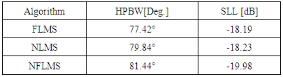
Table 2 represents the analysis of Half Power Beam Width (HPBW) and Side Lobe Level (SLL) of Planar Uniform Circular Array.Table 2. Planar Uniform Circular Array
 |
| |
|
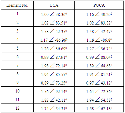
Below is the excitation table generated by the two circular array configurations taken using normalized fractional least mean squares algorithm.Simulations conducted show that planar uniform circular arrays have better performance than the other geometry. A more precise main beam pattern is also seen from the results and half power beam width values. Additionally, it is also proven that NFLMS has better convergence than LMS, FLMS and NLMS algorithms which when used with PUCA, provides better results. In this case, SLL for UCA is -19.21 dB and for PUCA it is -19.98 dB. HPBW for UCA is 80.12° and for PUCA it is 81.44°. Therefore, NFLMS algorithm is better for synthesizing planar uniform circular arrays compared to the other three algorithms.Table 3. Amplitude and Phase Excitations generated by NFLMS algorithm
 |
| |
|
4. Conclusions
As seen from the results obtained using MATLAB software the planar uniform circular array (PUCA(4:8)) using NFLMS as the weighting scheme is able to steer the main beam in the desired direction and place nulls at interference signals more efficiently, also the side lobe levels are considerably reduced when compared to UCA. Improved results can be seen when using hexagonal arrays and octagonal arrays which may be opted as a future work.
References
| [1] | Constantine A. Balanis, Antenna Theory: Analysis and Design. New Jerse Wiley-Interscience, Third Edition, 2005. |
| [2] | Rahim, Tehseen. Directional pattern synthesis in circular arrays of directional antennas. Diss. University of London, 1980. |
| [3] | Noordin, N. H., Zuniga, V., El-Rayis, A. O., Haridas, N., Erdogan, A. T., & Arslan, T. (2011, November). Uniform circular arrays for phased array antenna. In Antennas and Propagation Conference (LAPC), 2011 Loughborough (pp. 1-4). IEEE. |
| [4] | Vescovo, R. (1993, June). Array factor synthesis for circular antenna arrays. In Antennas and Propagation Society International Symposium, 1993. AP-S. Digest (pp. 1574-1577). IEEE. |
| [5] | Amanpreet kaur, Amandeep singh, (2012, April). Comparison between the Radiation patterns of Uniform Circular Array and Uniform Planar Array (IJCNWC), ISSN: 2250-3501 Vol.2, No.2. |
| [6] | Geravanchizadeh, M., & Osgouei, S. G. (2011, May). Dual-channel speech enhancement using normalized fractional least-mean-squares algorithm. In Electrical Engineering (ICEE), 2011 19th Iranian Conference on (pp. 1-5). IEEE. |
| [7] | Ioannides, P., & Balanis, C. A. (2005). Uniform circular and rectangular arrays for adaptive beamforming applications. Antennas and Wireless Propagation Letters, IEEE, 4, 351-354. |
| [8] | Sayed, A. H. (2011). Adaptive filters. John Wiley & Sons. |
| [9] | Haykin, S. S. (2008). Adaptive filter theory. Pearson Education India. |

 Abstract
 Reference
 Full-Text PDF
 Full-text HTML