-
Paper Information
- Paper Submission
-
Journal Information
- About This Journal
- Editorial Board
- Current Issue
- Archive
- Author Guidelines
- Contact Us
American Journal of Signal Processing
p-ISSN: 2165-9354 e-ISSN: 2165-9362
2015; 5(2): 40-50
doi:10.5923/j.ajsp.20150502.03
Landmark-Based Robot Localization Using a Stereo Camera System
 Abstract
 Reference
 Full-Text PDF
 Full-text HTML
Nguyen Tan Nhu, Nguyen Thanh Hai
Faculty of Electrical and Electronics Engineering, HCMC University of Technology and Education, Vietnam
Correspondence to: Nguyen Thanh Hai, Faculty of Electrical and Electronics Engineering, HCMC University of Technology and Education, Vietnam.
| Email: |  |
Copyright © 2015 Scientific & Academic Publishing. All Rights Reserved.
This paper proposes the method of 2D localization using a stereo camera system. The navigating space of robot with landmarks for robot localization is an indoor environment. Therefore, the main task is that features of landmarks that are unchanged in scales and directions are determined from the left and right images. The algorithm of the Scale-Invariance Feature Transform (SIFT) is applied for transformation of all features of the landmark image to multi-dimensional vectors. Moreover, the pixel locations of the detected landmarks on the left and right images are transformed to distances using the geometric projections. The coordinates of each detected landmark and the distances to the robot are finally combined using Euclid distance equations for estimating the robot location. Results are shown to illustrate the effectiveness of the proposed stereo camera system with the consuming time and the low cost, but it still satisfies the localization task.
Keywords: Robot localization, SIFT algorithm, Landmark recognition, Geometric projections, Distance measurement
Cite this paper: Nguyen Tan Nhu, Nguyen Thanh Hai, Landmark-Based Robot Localization Using a Stereo Camera System, American Journal of Signal Processing, Vol. 5 No. 2, 2015, pp. 40-50. doi: 10.5923/j.ajsp.20150502.03.
Article Outline
1. Introduction
- Localization is one of the most important functions in the navigation of automatic robots. Some robots with modern methods have developed with the ability of automatically moving from the initial location to the assigned one to accomplish tasks been entrusted by humans. In order to determine when the robot reaches its destination, the localization function has to operate accurately and continuously. Therefore, the accuracy and reliability of robot localization are keys to the success of navigating tasks [1].The accuracy and reliability of the localization function are mainly dependent on how distances from the robot to landmarks are measured [2]. Sonar sensors were firstly and commonly applied to robotics in getting distances of surrounding objects from the robot due to the simplicity and speed of localization, but this method was limited in kinds of landmarks being able to be recognized. This method is able to recognize objects having flat surfaces such as walls. Consequently, most small-surface objects such as chairs, tables, and other moving ones are impossibly detected. In the other hand, the accuracy of this method is not very high [3].The drawbacks of applying sonar sensors in localization can overcome using the alternation of laser sensors. The range of the laser is much larger than that of the sonar, but it is not able to recognize complex objects in surroundings [4]. In general, data obtained using sonar and laser sensors are just distances [5]. The most valuable ability of image processing methods in localization was the recognition of landmarks disposed and fixed in a navigation space. Moreover, these methods could be used to determine distances from the robot to the landmarks for making localization systems [6].When image processing techniques were applied in robotics, recognition algorithms have become more important. Recognition techniques based on colours were firstly used, but the results are much dependent on the light intensity of the environment [7]. Other methods solving this problem are often Fourier and Wavelet transform-based recognition for transforming the grey level variances to frequency domain so that the results are independent from light intensity [8].Objects in the navigating space are variant in scales and directions appeared on the captured images for recognizing. Therefore, recognition algorithms tend to focus on the features of objects such as edges, lines, and points [9]. David G. Lowe invented the technique for detecting features in an image without change in scales and directions appeared on the capture images. Thus, image processing algorithms have been applied in distance estimation based on the stereo vision technique in recent decades [10]. Therefore, the localization systems applied image processing algorithms are going to be served simultaneously with using both distance estimation and object recognition [11-15].Several applications taking advantages of image processing in the field of localization have recently been being commonly developed. Artificial landmarks designed specifically for underwater image recognition are used to support for MCL in order to gain the accuracy of underwater localization [16]. Barcodes are recognized and measured distances by image processing techniques so as to determine location of the KINECT sensor [17]. An open source of triangulation tool box just introduced helps landmark-based localization tasks simplify their estimation of location in 2D or 3D space [18]. Based on the information of the landmarks gotten by image recognition methods, an indoor localization system has been developed to support visual impairment individuals in their moving [19]. However, the cost of stereo cameras utilized in these localizing systems is one of the drawbacks of the systems using image processing, and the issue is that the total cost of localizing systems must be reduced so that it can be suitable for everyday applications.This research proposes the method of robot localization based on landmarks using a stereo system. The navigating environment of the robot is set up landmarks with own coordinates. Therefore, the main task is to localize the robot in the navigating space environment. In order to determine the robot location, the left and right images are captured for detection of features of landmarks without change in scales and directions, in which the SIFT algorithm is employed to transform to multi-dimensional vectors for easily detecting using Euclid's distance equation. Moreover, the pixel locations of the detected landmarks are transformed to distances using the geometric projection for stereo calibration. The coordinates of each d landmark and the distances from the landmark to the robot are combined based on Euclid distance for estimation of the robot location. The results will represent calculation of the time related to localizing cycle and low cost of the proposed method.
2. Basic Methods
2.1. Location Estimation Based on Known-Position Landmarks
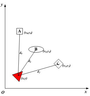 | Figure 1. The geometric model of robot localization in 2D space |
 is moving in the 2D space of
  , which is represented by the fixed landmarks having the own predefined coordinates. In this paper, there are three landmarks such as
  ,
,  , and
, and  are used. Distances as
  , and
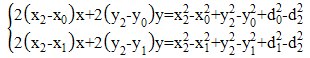
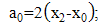
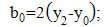
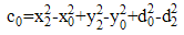
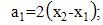
, and  measured from the robot to each landmark of A, B, and C are symbolized, respectively. As a result, the relationship between these distances and the coordinates of the robot, A, B, and C in the system is shown by the following equations:
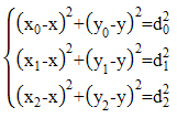 | (1) |
 | (2) |
 | (3) |
 | (4a) |
 | (4b) |
 | (4c) |
 | (5) |
 | (6a) |
 | (6b) |
 | (6c) |
 | (7a) |
 | (7b) |
 | (7c) |
2.2. Scale-Invariant Feature Transformation
- The Scale-Invariant Feature Transformation (SIFT) method allows to transfer the invariant feature of the image object to scales and directions appeared on another image [10]. Therefore, the pixel locations on the sample object image with no change in various scales and the determined locations are found so that the features recognized are not depend on the appeared direction on the corresponding image.
 | (8) |
 | (9) |
 | (10) |
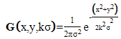
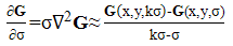
 in which k is called the scale factor. As a result,
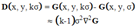
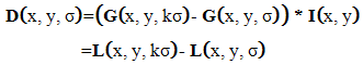
  is computed Equation (9). According to the theory [20], the minimum and maximum locations of the Laplace transformation of Equation (10),
  can be computed using Equation (11) and are scale-invariant pixel locations on the sample image of the object. As shown in Equation (12), the Laplace transform of the Gaussian function is approximately equal to the difference of continuous scale versions of
  .Consequently, the scale-invariant pixel locations are the minimum or maximum locations of
  .
. | (11) |
 | (12) |
 | (13) |
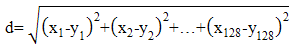
 are the elements of the first vector,
  are the elements of the second vector, and
  is the distance between the two vectors.
2.3. Geometric Projection
- This section presents briefly the geometric projection for distance measurement using stereo vision techniques [21] as shown in the Figure 2. The geometric model contains two single cameras which have the same configuration and are installed with T from the central left image plane to the central of right image plane. The focal length of the left and right camera is symbolized by f.
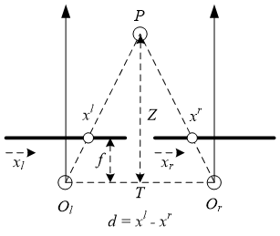 | Figure 2. Representation of a stereo camera system |
 and
and  respectively. Because the left and right image planes are co-planed together, in which the y-coordinates of the left and right projected points of P are the same. Thus, the difference occurs in the x-coordinate, which is represented as
  and called the disparity between the left and right image point. The distance,
  from the point P to the stereo camera is defined as the distance from the plane containing two focal points of the left and right camera to the point P. Therefore, the relationship between the distance
  and the disparity is determined using the following equation:
 | (14) |
3. Proposed Method
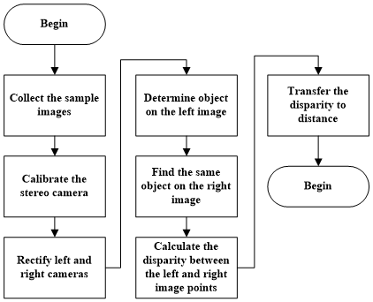
- This section presents briefly the algorithm of localization in 2D space. In particular, the two most important problems in the localization system are the scan-invariant object recognizer and the stereo vision distance estimator as described in Figure 3.
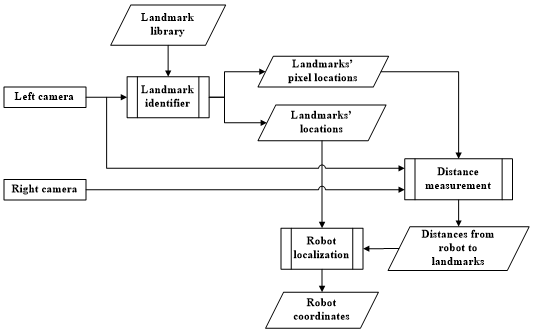 | Figure 3. Block diagram of the proposed localization system |
3.1. Localization System
- The block diagram of the proposed localization system is shown in Figure 3, in which the Left camera and the Right camera installed with the same structure to be a stereo camera system for capturing surrounding images, including the predefined landmarks.The existence of landmarks is determined by Landmark identifier based on an algorithm of object recognition which has the ability of recognizing objects appeared differently in scales and orientations compared with the original sample images. Moreover, the estimated Landmarks' pixel locations on the left image are combined with their pixel locations on the right image to output their distances from the stereo camera installed with on the robot. The Landmarks' locations on 2D space specified by Landmark identifier and distances from the robot to recognized landmarks measured by the Distance measurement are added to the Robot localization, using Equation (1) to output the robot location corresponding to the global coordination.According to Figure 3, two most important problems beside the Robot localization are Landmark identifier and Distance measurement. In particular, the Landmark identifier is applied as a recognition algorithm named the SIFT. This algorithm allows to identify objects in different scales and directions compared with the original image for detection of the appearance of landmarks during navigation. In addition, the Distance measurement means that measuring the distances from detected landmarks to the stereo camera using the rules of the geometric projection.
3.2. Scan Invariant Object Recognition
- The fundamental task of the localization system is the process of recognizing landmarks that have specified features distinguished. For processing this problem, the SIFT method for recognition is utilized due to its suitability for the requirement of detecting landmarks appeared in various scales and directions.Figure 4 illustrates steps for recognition task. The most essential requirement of the task is that there is a library of features for each landmark and this features specialized for each landmark are invariant in scales and directions. Therefore, these features are determined on the sample landmark image using the Gaussian method so that their positions do not change in variations of scales. Each feature location is transformed to multiple-dimensional vector which is independent to its appeared direction on the left image.
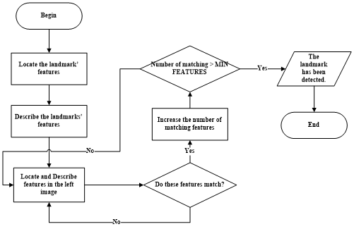 | Figure 4. Representation of landmark recognition |
 | Figure 5. Features in a landmark's sample image |
 | Figure 6. A landmark is detected on the left image frame |
3.3. Distance Measurement Using Stereo Vision
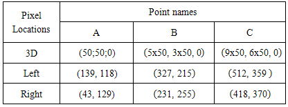
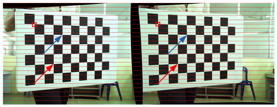
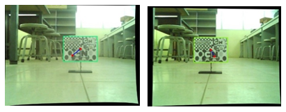
- In addition, distance measurement is very important in the localization system. Figure 7 shows the processes of utilizing stereo camera in measuring distance. The precision of the localization results is strongly dependent on the precision of distance measuring. Although the precision of stereo camera is not very good, the utilization of stereo camera in estimating distances makes the localization more compact. For better information obtained, the stereo camera system as described in Figure 8 is calibrated firstly to determine its stereo parameters in the stereo camera model before determining distances. The stereo camera with the frame size of 640x480 is configured to have the resolution of 24 bits per each pixel.
 | Figure 7. The process of utilizing stereo camera in measuring distance |
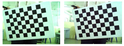 | Figure 8. A pair of the two sample images obtained from the left and right camera system |
 | Figure 9. Example of an image with acceptable resolution |
|
 | Figure 10. Example of an image with acceptable resolution |
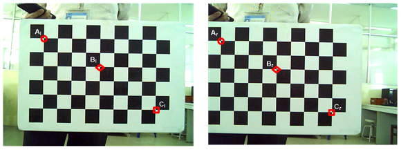
 | Figure 11. Detected landmarks on the rectified left and right images; (a) detected left landmark; (b) detected right landmark |
4. Experimental Results
- There are many factors affecting to the localization results which can be classified into two main influences of the recognized landmark and measured distance due to key contributions to the localization system for determination of robot coordinates in this paper.
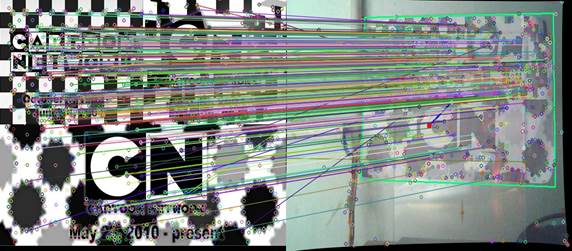
4.1. Results of Landmark Recognition
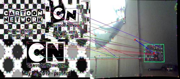
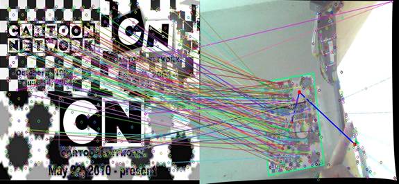
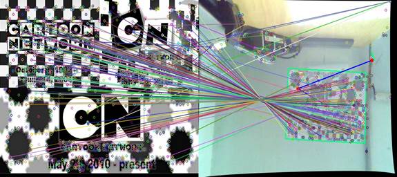
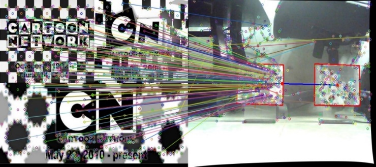
- The proposed algorithm for landmark recognition was applied to detect the landmarks appeared in various scales and direction on other images. Figure 12a shows the result of the detected landmark appeared from the nearest distance on the left image. Due to the large number of the matching points with lines connected between the feature on the left sample image and the corresponding matching ones on the right image, the landmark is easily detected. However, when the distance from the landmark to the camera is much farther, the number of the matching points is dramatically increased, so the landmark is hardly detected as shown in Figure 12b.
 | Figure 12a. Detected landmark appeared from the nearest distance on the left image |
 | Figure 12b. Detected landmark appeared from the much farther distance on the left image |
 | Figure 12c. The detected landmark rotated from the origin 90o |
 | Figure 12d. The detected landmark rotated from the origin 180o |
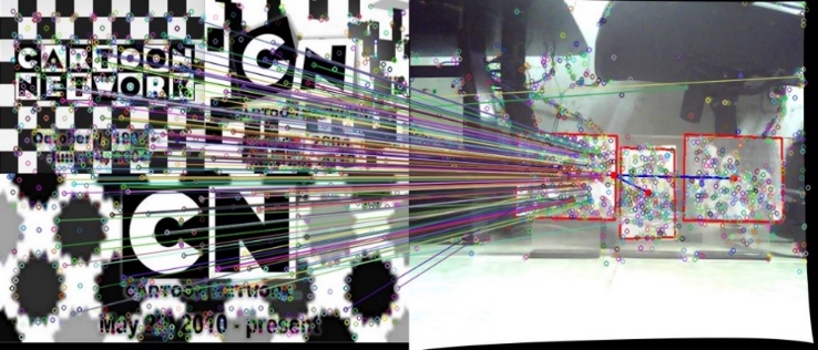
 | Figure 12e. The two detected landmarks simultaneously appeared on the captured image |
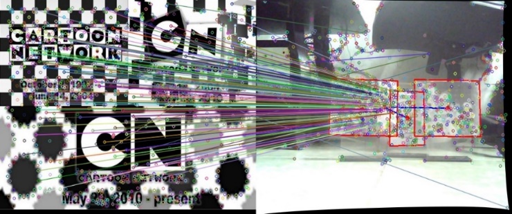
 | Figure 12f. The three detected landmarks simultaneously appeared on the captured image |
 | Figure 12g. The obscured landmark still detected by the algorithm |
 | Figure 13. The landmark with the most number of 2289 features |
 | Figure 14. The landmark with the least number of 924 features |
 | Figure 15. The landmark with the least number of features but the largest range of successful recognition |
4.2. Determination of Landmark Distances
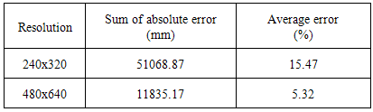
- The paper proposed the method of determining landmarks from landmark to the stereo camera system. The range of the distance measurement is strongly dependent on the resolution of the camera used to collect image data for localization. Figure 16 shows the relationship between the image resolution 240×320 and the range of landmark distances and produces the range of linear results is from 500 mm to 4000 mm. Figure 17 describes the result of landmark distance for resolution 480×640 and the range of linear results is from 500 mm up to 8000 mm. Thus, this addresses out that the large resolution produces the longer measured distances. In addition, the accuracy of the results is affected by the image resolution, in which Table 2 shows the percentage of the error according to the two values of resolution. In the resolution of 240×320, the error is up to 15.47%, but the error is dramatically decreased to 5.32% when the resolution 640×480 is doubled.
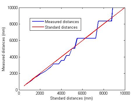 | Figure 16. Measured distances for resolution240x320 |
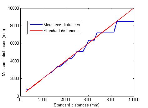 | Figure 17. Measured distances for resolution 480x640 |
|
4.3. Estimated Locations
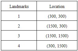
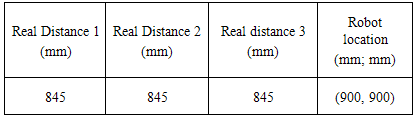
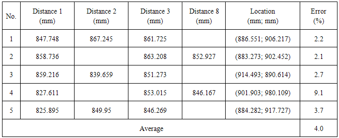
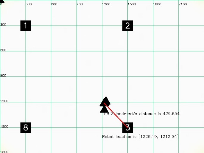
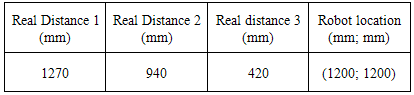
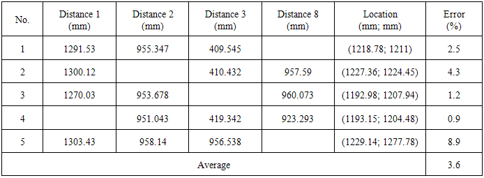
- The results of stereo localization are directly dependent on the quality of the landmark recognition and the measured distance. More results of localization measured from the two different positions of robot in 2D space are represented. Figure 18 shows the first position of the robot in the dynamic environment. The environment with four landmarks at the coordinate values is predetermined as shown in Table 3. Moreover, the real distances from the robot to each landmark and the real location of the robot are shown in Table IV. Each position is localized five times with percentage errors and the average error of the localization is 4.0% are as in Table 5.
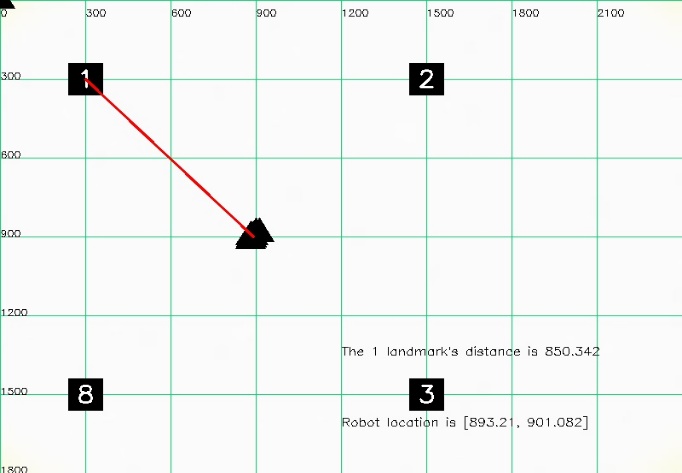 | Figure 18. The first position of the robot in the dynamic environment |
|
|
|
 | Figure 19. The second position of the robot in the dynamic environment |
|
|
5. Conclusions
- The paper proposed the method of the robot localization in the indoor environment using the stereo camera system. In this project, Landmarks were used for robot localization, in which landmark distances and landmark recognition were worked out using geometric projection. In particular, the SIFT algorithm was employed for determination of landmark features with multi-dimensional vectors. In addition, the coordinates of each detected landmark were combined with distance to the robot for estimation of the robot location. With this proposed approach in this research, many results were obtained and obviously estimated with the small errors. Moreover, the results with error dependent on the resolution of each image were represented.