Abdulrazaq Abdulaziz1, Abdulmalik S.Yaro2, Ashraf A. Adam3, Mahmoud T. Kabir2, Habeeb B. Salau3
1Faculty of Electrical Engineering, Universiti Teknologi, Malaysia
2Department of Electrical and Computer Engineering, Ahmadu Bello University, Zaria, Nigeria
3School of Engineering and Engineering Technology, Federal University of Technology, Minna, Nigeria
Correspondence to: Ashraf A. Adam, School of Engineering and Engineering Technology, Federal University of Technology, Minna, Nigeria.
| Email: |  |
Copyright © 2015 Scientific & Academic Publishing. All Rights Reserved.
Abstract
Air traffic control (ATC) radar has been the main sensor for the detection and monitoring of commercial aircrafts for air traffic management. Typical modern ATC radar consists of a primary radar and secondary radar which is limited by high acquisition, installation and maintenance cost. Automatic Dependent Surveillance-Broadcast (ADS-B) system is the next generation locating system to complement existing ATC radar system. This paper looks into the design of an optimum receiver to decode ADS-B signal. The work consists of three sections; modulator, demodulator and performance verification. To ensure compatible to the industrial standards, the message format and its verification process is based on the ICAO (International Civil Aviation Organizations) standards. A non-coherent detection structure (based on energy detection) was adopted at the receiver to improve performance at low signal-to-noise ratio (SNR) condition. Performance results show that simulated bit-error rate (BER) approximately matches the theoretical BER plot for non-coherent BPPM up to SNR values of 8dB. Also packet error rate (PER) is one at SNR less than 8 dB and zero (no packet error) at SNR of 12dB and above.
Keywords:
Air Traffic Control (ATC), Signal-to-Noise ratio (SNR), Bit-Error Rate (BER), Packet Error Rate (PER)
Cite this paper: Abdulrazaq Abdulaziz, Abdulmalik S.Yaro, Ashraf A. Adam, Mahmoud T. Kabir, Habeeb B. Salau, Optimum Receiver for Decoding Automatic Dependent Surveillance Broadcast (ADS-B) Signals, American Journal of Signal Processing, Vol. 5 No. 2, 2015, pp. 23-31. doi: 10.5923/j.ajsp.20150502.01.
1. Introduction
As air traffic increases yearly, the need for better surveillance systems is essential especially when navigating through poor conditions (such as adverse weather). Air traffic control (ATC) has been using radar based systems as the navigational aid of choice but due to exponential increase of air traffic, more sophisticated and advanced systems has been developed [1]. A radar system typical comprises of primary surveillance radar (PSR) and secondary surveillance radar (SSR). These surveillance technologies are coupled with radio communications to build a complete ATC system since 1950s [2]. PSR is totally passive and does not require the action of any of the object being tracked but has a setback of not provide the altitude or identity of the aircraft; higher update rates, poor resolution and high transmit power for long distances. SSR is an extension of PSR and evolution of military identification friend or foe (IFF) to cater for most weaknesses of the PSR but still retains some weaknesses such as poor resolution and various modes (A/C/S) indiscrimination [3]. Mode A/C basically provides identification and altitude while mode S in addition to previous aforementioned functions of mode A/C allows unique addressing of targets with the aid of unique 24 bit aircraft addresses using a two-way data link between the ground station and aircraft for information exchange. Unlike PSR and SSR mode A/C, mode S has the ability to resolve two aircraft when they are at the same geographical position and can also discretely interrogate single aircraft transponders [3]. Current radar systems are quickly reaching their maximum capacity as a result of shortcomings in visibility propagation, limitation due to noise, line-of-sight and voice communications limitation and also the lack of digital data links [4][5]. Additionally, synchronous garbling is another major concern in which the interrogation signal of SSR invokes a response from more than one aircraft, causing the replies sent by both aircraft to overlap at the receiver leading to loss of information at the ground station ATC facility. These and more limitations led to the advent of a new technology commonly referred to as automatic dependent surveillance broadcast (ADS-B). This technology typically involves airplanes constantly sending in real time position and flight parameters using global positioning system (GPS) [6].ADS-B’s main purpose is to determine the position of an aircraft and then broadcast same information. This information is broadcasted along with its call sign, heading, altitude and the identity of the aircraft automatically (i.e., without secondary surveillance radar (SSR) interrogation signal) to other aircraft and to air traffic control ground facilities. ADS-B is similar to mode S for the fact that it uses the same transmission frequency of 1090 MHz and squitter messages (messages that doesn’t require any interrogation while being transmitted). It differs from mode S in that the message is 112 bits, 120 micro seconds long and uses extended squitter messages [7] [8]. This work develops algorithm for decoding and interpreting received demodulated ADS-B signal and Monte Carlo simulation is performed at a given range of signal-to-noise ratio (SNR) to determine the accuracy of the system. Pulse position modulation techniques (PPM) was used in the encoding and decoding process to implement ADS-B data while cyclic redundancy check (CRC) error detection technique is applied for receiving ADS-B signal at the ground control station. An intermediate frequency (IF) of 10 MHz, with sampling frequency of 40 MHz was used with additive white Gaussian noise (AWGN) channel as the noise model. The rest of work is organized as follows; section II provides an overview of ADS-B while section III describes the steps involved in achieving the stated objectives. Section IV presents results, discussion, and analysis of the system’s capabilities. Finally, the paper is concluded.
2. Overview of ADS-B Technology
ADS-B is automatic in that it does not require any action or input by the pilot and no interrogation from the ground is required. It is dependent because it relies on on-board equipment to gather the ADS-B data and broadcast it to other ADS-B users and it is a means of providing surveillance and traffic coordination [3].
2.1. General overview of ADS-B System
ADS-B was created with compatibility and ease of transition in mind. It was built using similar aspects of the current mode S aircraft surveillance transmission mode. The ADS-B system is a system on board an airplane or aviation related vehicle which allows this to transmit its position (GPS), speed, etc. Figure 1 shows the basic framework of how it works. 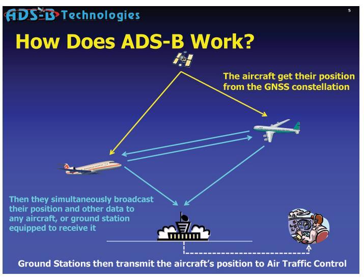 | Figure 1. How the ADS-B system works |
An ADS-B packet is made of relevant information, transmitted every one second [9]. This packet containing the state vector can then be received by any ADS-B equipped devices within range of the transmitting device. This means that the packets will not necessary be received by anyone and no acknowledgement from receiving devices is expected. The information carried in the packet can then be used by other airplanes or ground stations to monitor the surrounding airspace such as airport [10]. The equipment used for ADS-B is also used by airplanes to receive other services called Traffic Information Services-Broadcast (TIS-B) and Flight Information Services- Broadcast (FIS-B). TIS-B is used to send additional information about the surrounding airspace to airplanes, and is particularly helpful when there are planes which are not equipped with ADS-B. The sent data is obtained by radar technology. FIS-B provides a better image of the surrounding meteorological and aeronautical situation [11].The ADS-B system is currently only a requirement in Hudson Bay Area, USA, but by the year 2020 it will also be a requirement in Europe, Australia and the entire USA. With the release of the Federal Aviation Administration (FAA) final decision [12], they solidified their choice to move forward with the implementation of ADS-B technology as part of the next generation (NextGen) national airspace system. In addition, in August of 2007, the FAA awarded the International Telephone and Telegraph (ITT) corporation a contract to field a national system capable of providing a comprehensive set of ADS-B services for the United States [13] [14]. Because the FAA is charged with providing a safe and efficient airspace for both civil and military aircraft [15], the armed services are also affected by the FAA’s decision.One of the biggest advantages of ADS-B is the ability to provide coverage where radar could not reach before such as transoceanic navigation. Other advantages of ADS-B surveillance systems include increased efficiency, increased safety, improved visibility, and reduced impact on the environment. ADS-B gives ATC a clear picture of the airspace, meaning they can better manage it to allow for a shorter time between take offs and landings, without any sacrifice in safety. This reduces the time that an aircraft needs to spend in the air waiting for landing clearances and in turn decreases the time that ATC needs to spend on controlling each plane. An important benefit of the reduced waiting time is the elimination of wasted fuel. This drives down flight costs and reduces the environmental impact. Each aircraft with ADS-B has a complete picture of the airspace surrounding it, something that wasn’t possible with traditional radar. The collision prevention systems can use this data and the increased visibility that it provides. Unlike traditional radar, the ADS-B signals do not deteriorate as the range increases and the plane is either available or out of range. Likewise, they are very rarely affected by poor atmospheric conditions, weather and signal deterioration. However ADS-B has a high reliance on aircraft transponders which can cause a major issue to the ATC in some environments. Also when satellites are out of service, some outages are expected as a result of poor GPS geometry. Currently, there are stability, integrity and credibility problems associated with ADS-B [8].
2.2. ADS-B Message Format
ADS-B signals from aircraft to ground stations are transmitted at 1090MHz.They contain 112 bits of data, encoded using pulse position modulation with a data rate of 1Mbps.The ADS-B message is preceded by a 8us preamble which serves to both mark the start of a transmission and to allow the receiver to unambiguously determine the position of the high and low bits within a message [15]. Figure 2 illustrates the components of an ADS-B message.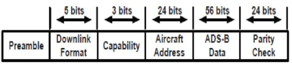 | Figure 2. ADS-B Message Format |
Preamble is the first field of the ADS-B message format as shown in figure 2. This field of 8 microsecond duration is a fixed bit sequence that can allow the receiver to identify and synchronise with a message received. Next to preamble is the Downlink Format (DF) field which is the first field of the ADS-B message, it is used as an indication of the type of message that is being transmitted. For extended squitter messages, it is set to 17 or 10001(binary). The next field is the capability (CA) field or subtype field. This describes the specific data being transmitted by the ADS-B message and is set to binary “101” for all tests.Following the capability field is the aircraft’s ID, which is 3-byte that contains the ICAO designation for each aircraft. Following the aircraft ID are the 56bits of ADS-B data, containing information about the altitude, latitude, and longitude of the aircraft. Finally the last field is the parity check, which is 24bits. The 24bit field is reserved as an error detection code that can help a receiver to detect errors in the received message. Pulse position modulation (PPM) is used for encoding and transmitting the message. This is a modulation scheme that is relatively simple for a 1090 MHz receiver to decode in the presence of non-overlapping (in time) replies. The PPM for each pulse results in the data occupying either the first or second half of the entire pulse, which in effect is the same as Manchester encoding (Figure 3).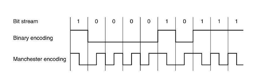 | Figure 3. Manchester encoding |
2.3. The Error Control Technique
This is an integral part of digital communication. It is important simply because errors usually caused by interference due to noise, channel impairment and multipath fading is un avoidable in any given communication systems, it is therefore necessary to develop a technique to control it. Two methods for error control are automatic repeat request (ARQ) and forward error correction (FEC). ARQ which was used in this work utilises an error detection code like cyclic redundancy check (CRC) and parity check. The parity bit for ADS-B data are calculated through a cyclic redundancy check (CRC) with a generating polynomial and using the first 88 bits of the ADS-B message and then appends the parity to the end of ADS-B message. The CRC generator polynomial used for generating the parity bit for this project is shown below [16]: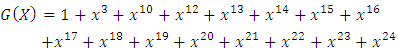 | (1) |
3. Design Methodology
Using various sources, most notably, International Civil Aviation Organization (ICAO) [3], a system was created with the ability to received ADS-B messages and subsequently decodes them. The process included multiple encoding equations and transformation into hexadecimal representation to ensure the proper waveform for ADS-B messages. Steps undertook are presented in the subsequent subsections
3.1. ADS-B Packet Formation
For this work, a real ADS-B (DF 17 hexadecimal message format) excluding the preamble was obtained from air traffic control data used to perform necessary simulation. The extended squitter packet consists of 28 hexadecimal characters which is equivalent to 112 binary bits. The structure of an ADS-B packet format is shown in Figure 4.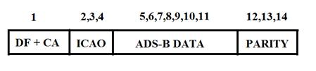 | Figure 4. Extended squitter packet |
From Figure 4, the first byte contains the DF (Downlink Format) code and CA (Capability). The DF number tells the decoder whether it is dealing with a short or extended squitter packet. Once the hexadecimal characters have been converted to binary; all extended squitter packets begin with 10001 followed by 3 more bits to indicate the CA code. The next 3 bytes is a unique ID assigned to every aircraft by the ICAO. Following the ICAO aircraft address is a 7 byte ADS-B data which consist of flight information such as the altitude, latitude, and longitude of the aircraft. The last 3 byte is the parity check which is used by the receiver for error detection.
3.2. CRC Check Generation and Encoding
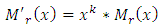
Excluding the preamble, the next 11 bytes which include the DF, CA, ICAO aircraft ID and ADS-B data is used to generate the 3 byte parity bits for error detection at the receiver. This is done by performing modulo 2 division of the 11 bytes with a 25 bits CRC generator polynomial which results in a remainder of 24 bits. This 24 bits remainder is then XORed with the 3 byte transponder address after which it is appended at the end of ADS-B data making the packet length to be 112 bits. The process of the CRC encoding can be mathematically explained as shown in the figure 5.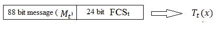 CRC encoding at the transmitter;
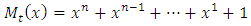 | (2) |
 | (3) |
where Mt(x) is the ADS-B message polynomial, G(x) is the CRC generator polynomial, and FCSt is the transmitted frame check sequence bits. Thereafter, the encoded message is given by;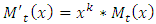 | (4) |
Message shift by k bits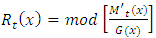 | (5) |
Rt(x) is the remainder obtained after performing the modulo2 division of ADS-B message with the generator polynomial which is also equal to the parity bit polynomial. FCSt is found by XORing of Rt(x) with the 24bit Air craft address which is then appended at the end of the ADS-B datagraphs must be indented. All paragraphs must be justified alignment. With justified alignment, both sides of the paragraph are straight.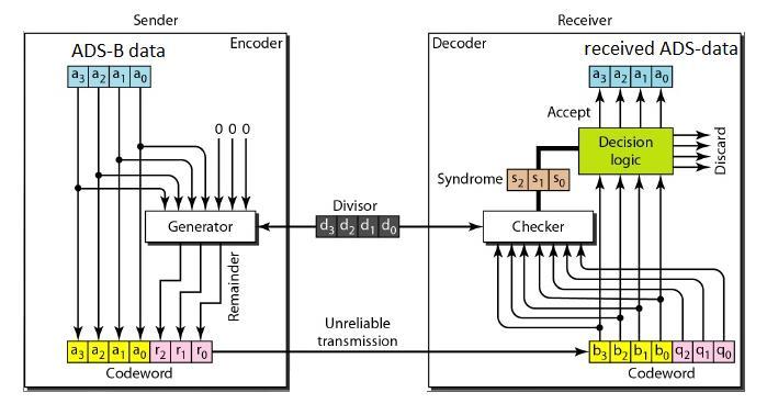 | Figure 5. CRC Generation |
3.3. Preamble Generation
The preamble is 8microsecond special bit sequences that consist of 4 pulses with a pulse width of 0.5 microseconds that allows the receiver to identify and synchronise with a message received for decoding. Figure 6 shows the ADS-B packet including the preamble.In this work, a carefully selected random bit sequence of (1 0 1 0 0 0 0 1 0 1 0 0 0 0 0 0) is used to represent the preamble. This means that a binary bit 1 represent a high pulse while bit 0 represent a low pulse. The generated preamble is then attached at the beginning of the 112 bit previous generated packet which includes DF, CA, ICAO ID, ADS-B data and parity check bit.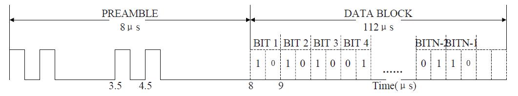 | Figure 6. ADS-B packet waveform |
3.4. Digital Modulation and Transmission
The generated 128 bit is then modulated and transmitted using BPPM with a carrier frequency of 1090MHz. BPPM modulation is used to enable a 1090 MHz receiver to decode the received ADS-B packet in the presence of non-overlapping (in time) replies. The PPM for each pulse results in the data occupying either the first or second half of the entire pulse, which in effect as already mentioned is the same as Manchester encoding. This is illustrated in figure 7.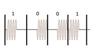 | Figure 7. Modulated Manchester encoding |
After the packet is demodulated, CRC error detection is performed to determine if the received packet is valid i.e has the right ICAO aircraft ID. The CRC detection can be mathematically illustrated below;At the receiver after demodulation;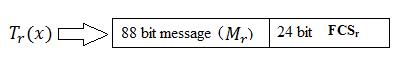
 | (4) |
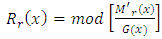 | (5) |
Rr(x) is the decoded remainder of the decode received message  obtained at the receiver which is also equal to decoded parity polynomial. To get the received aircraft address Rr(x) is XOR with FCSt (transmitted frame check sequence bits). If no error in the received package; then the transmitted aircraft address will be the same as the decoded aircraft address.
3.5. Message Reception and Interpretation
After the preamble has been detected, the individual bits need to be identified for message decoding. The bits are detected through a threshold setting based on the pulse amplitudes of the preamble. This requires the pulses to remain at relative constant amplitude throughout transmission. Pulses violating the threshold could cause bit errors and ultimately the message would be discarded. Once the bits have been received successfully, then, the bits will be decoded based upon the message type and the message format. DF17 messages have a particular placement for the individual components of the message. To ensure proper decoding, the format must be known to ensure the correct bits are used for altitude, aircraft ID, etc. The ADS-B message is broken into six parts including the preamble as shown in Figure 8.After the packet has been received and demodulated, it is converted to binary bits as illustrated below [17];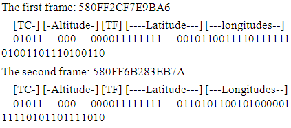
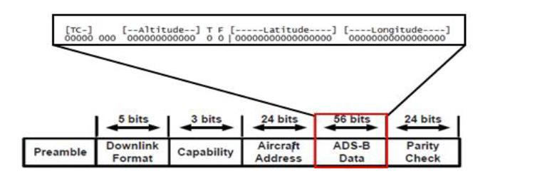 | Figure 8. ADS-B packet showing the content of the ADS-B message field |
The frame is interpreted as mention below:First 5 bits are the type code (TC) which is 11.A TC 11 decodes to the following fields:Bits 6 and 7 are the surveillance status.Bit 8 indicates the antennas used.Bits 9 (MSB) to 20 (LSB) contain the altitude.Bit 21 contains the T (Time) bit. T in this case is 0 which means we are not synchronized to current local time in coordinated universal time (UTC).Bit 22 contains the F flag to indicate which compact position reporting (CPR) format is being used (even or odd).Bits 23 (MSB) to 39 (LSB) contain the encoded latitude.Bits 40 (MSB) to 56 (LSB) contain the encoded longitude.The first frame has F flag = 0 so is even and the second frame has F (flag) = 1 hence it is odd. So we finally know that we can use our information to determine the position of this aircraft.
3.5.1. Altitude Decoding
The altitude comprises of 12 bits (bits 41 to 52). In order to decode the altitude, the 8th bit of the 12 bits counting from the most significant bit which also known as the Q bit is removed. This bit determined whether the altitude is being reported in 100 feet increment (set to ‘0’) or 25 feet increment (set to ‘1’). Once the increment has been determined, the first seven bits are shifted to the right resulting in eliminating the Q bit. The binary number left is then converted to decimal and this number is multiplied by the increment (25 or 100 feet). The resulting decimal value is added to 1000 which gives the altitude value of the aircraft [18].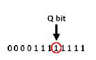 | Figure 9. Q bit representation for altitude |
Using an altitude bit pattern of 000011111111 as an example, the altitude is being report in 25 feet increase since the Q bit is set to one. The Q bit is then eliminated, which leaves 000001111111 or 127 decimal. Next, the decimal number is multiplied by 25 and the resulting product is added to 1000 which gives a resulting altitude of 2,175 feet.
3.5.2. Latitude and Longitude Decoding
The procedures and equations for latitude and longitude decoding is shown in [17]. A brief overview of the process is described below with an example.Lat(0) = 101100111101111112 / 9209510Lat(1) = 101011001010000012 / 8838510Lon(0) = 010011011101001102 / 3984610Lon(1) = 111101011011110102 / 125818101. To compute the latitude index j: 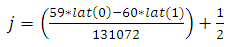 | (6) |
This gives j = 1.2. To calculate the magnitude of recovered latitude, Rlat(0) and Rlat(1): 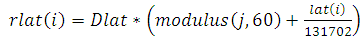 | (7) |
Where Dlat is known as zone size of the latitude, i is 0 for odd message and 1 for even messageSubstituting i=0 and i=1, the recovered latitude for odd end even message is;rlat(0) =10.2157745361328, rlat(1) = 10.2162144547802, using Const Dlat0 as Double = 6, and Const Dlat1 as Double = 360 / 593. To determine the number of longitude zone (NL) for Rlat(0) and Rlat(1):This is determined using the rlat from equation 7. A lookup table [38] is used to determine NL(rlat). From the look up table; NL(0) = 59 and NL(1) = 59 In a case where NL(0) and NL(1) are equal, then computation comes to a halt. But in this case, both NLs are equal, hence further computation in which the longitude index (M) and hence the global longitude is determined by using equation 8-11;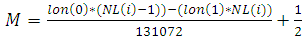 | (8) |
 | (9) |
Where n(i) = no of frames to be decoded;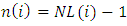 | (10) |
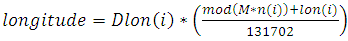
Dlon = width of the longitude zone, 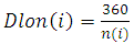 | (11) |
This result in a global longitude of 123.889128586342, therefore the latitude and longitude of the aircraft from which the two frames are received are 123.889128586342 and 10.2162144547802 respectively
4. Results and Discussions
Noise used in this work is modelled by the most common form and basic form of noise in radar and communication applications [19] [20] [21], which is the additive white Gaussian noise (AWGN). The Monte Carlo simulation is made of two loops; the inner loop to specify the number of iterations and the outer loop is used to specify the varying gain that will give various SNR (Eb/N0). The simulation result is divided into two categories: ADS-B parity checking and system performance in terms of bit error rate (BER) and that of packet error rate (PER) without considering receiver synchronisation. The equations used to obtain the theoretical BER plot for non-coherent BPPM and coherent BPPM are presented in equation 12 and 13 respectively [22]. All result generated based on 100 trials Monte Carlo simulation are presented in figures 10 and 11.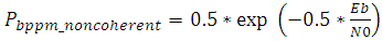 | (12) |
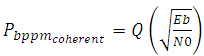 | (13) |
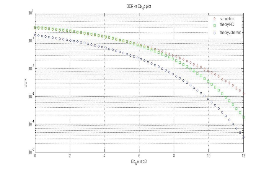 | Figure 10. BER versus Eb/N0 plot |
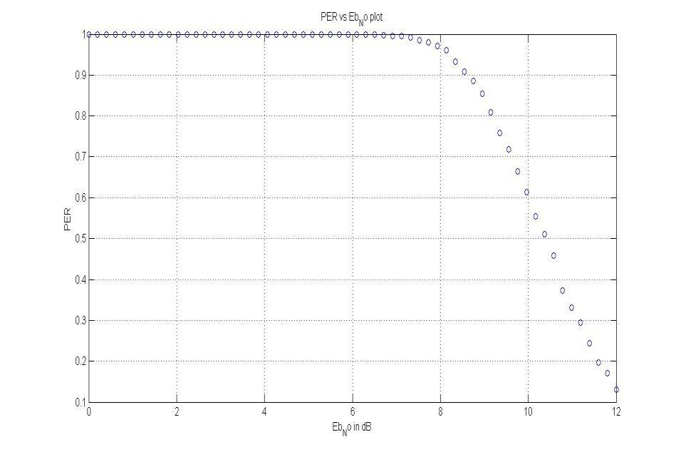 | Figure 11. PER versus Eb/N0 plot |
From Figure 10, it is seen that the obtained simulated BER approximately matches the theoretical BER plot for non-coherent BPPM up to an Eb/No values of 8 dB but slightly above it from Eb/No values of 8dB. This threshold value of 8dB is good when compared to other digital communication system. A coherent BPPM plot is also shown to indicate its superiority but was not implemented in this work as it is beyond the scope.Also from Figure 11 it is seen that the PER is 1 at Eb/No less than 8 dB (similar threshold value like that of the BER plot). This means that at values of Eb/No less than 8 dB all the received packets contained error as such resulting to higher BER after the Packets are process. As the values of Eb/No increases from 8 dB above, the number of packets with error reduces gradually until no packet has error which is at about Eb/No value of 12 dB. Above Eb/No of 12 dB, all the received packet have no error since the PER is
5. Conclusions
Samples of real aircraft data were decoded and the aircraft (ID) part of the real data was analyzed in designing an optimum receiver to decode ADS-B signal. From the analysis it was found that at low BER, the transmitted data is the same as the decoded data which implies there is minimum error of data received at the receiver. Monte-Carlo simulation was carried out to test for BER and PER performance of the system, the simulated BER was found to match approximately the theoretical BER when the effect of packet synchronization at the receiver is not considered. It expected that implementation of an ADS-B receiver with coherent architecture will offer better performance in terms of data rate and BER when compared to its counterpart non-coherent architecture.
References
| [1] | Gilbert, G. Historical development of the air traffic control system. Communications, IEEE Transactions on 21.5 (2006). |
| [2] | Livack, Gary S., et al. The human element in Automatic Dependent Surveillance-Broadcast flight operations. Digital Avionics Systems Conference, 2000. Proceedings. DASC. The 19th. Vol. 2. IEEE, 2000. |
| [3] | ICAO ASIA and Pacific. Guidance material on surveillance Technology Comparison Edition 1, 2007. |
| [4] | Purton, Leon, Hussein Abbass, and Sameer Alam. Identification of ADS-B system vulnerabilities and threats. Australian Transport Research Forum, Canberra. 2010. |
| [5] | Boci, Erton. "RF Coverage analysis methodology as applied to ADS-B design. Aerospace conference, 2009 IEEE. IEEE, 2009. |
| [6] | Coote, James. Mapping planes using ADS-B. Diss. Dissertation at University of Sussex, 2012. |
| [7] | Huang, Ming-Shih, Ram M. Narayanan, and A. Feinberg. Multiple targets estimation and tracking for ADS-B radar system. Digital Avionics Systems Conference, 2008. DASC 2008. IEEE/AIAA 27th. IEEE, 2008. |
| [8] | Valovage, E. M. A method to measure the 1090 MHz interference environment. Integrated Communications, Navigation and Surveillance Conference, 2009. ICNS'09. IEEE, 2009. |
| [9] | Federal Aviation Administration, Automatic Dependent Surveillance Broadcast (ADS-B) Out Performance Requirements to Support Air Traffic Control (ATC)Service; OMB approval of information collection, 14 CFR Part 91, Federal Register, vol. 75(154), August 11, 2010. |
| [10] | Bruno, Ronald, and Glen Dyer. "Engineering a US national Automatic Dependent Surveillance-Broadcast (ADS-B) radio frequency solution. IEEE Tyrrhenian International Workshop on Digital Communications-2008. TIWDC/ESAV 2008. 2008. |
| [11] | Boci, Erton, Shahram Sarkani, and Thomas A. Mazzuchi. "Optimizing ADS-B RF coverage. Integrated Communications, Navigation and Surveillance Conference, 2009. ICNS'09. IEEE, 2009. |
| [12] | United States Congress. Federal Aviation Act of 1958. Public Law No. 85-726, 85th Congress, 2nd Session. Washington: GPO, 1958. |
| [13] | Garcia, Manuel L., et al. Test for success: next generation aircraft identification system RF simulation. Integrated Communications, Navigation and Surveillance Conference, 2007. ICNS'07. IEEE, 2007. |
| [14] | Valovage, E. M. A method to measure the 1090 MHz interference environment. Integrated Communications, Navigation and Surveillance Conference, 2009. ICNS'09.. IEEE, 2009. |
| [15] | Labview Based ADS-B Receiver and Decoder (2012), Washington University St. Louis, USA. |
| [16] | E. Chnag, R. Hu, D. Lai, R. Li, Q. Scott, T. Tyan (2000), The Story of Mode S: An Air Traffic Control Data-Link Technology, Massachusetts Institute of Technology (MIT), Cambridge, MA. |
| [17] | Cardew, Edward J. (2010). ‘Decoding ADS-B Position’ in A Very Simple ADS-B Receiver. Edward Cardew Library. |
| [18] | Magazu III, Domenic. Exploiting the automatic dependent surveillance-broadcast system via false target injection. No. AFIT/GCO/ENG/12-07. Air force inst of tech wright-patterson (AFB OH) dept of electrical and computer engineering, 2012. |
| [19] | Nishimura, S., Mvuma, A. and Hinamoto. T. (2013). Tracking Properties of Complex Adaptive Notch Filter for Detection of Multiple Real Sinusoids. IEEE International Symposium on Circuits and Systems (ISCAS), 2013. 19-23 May 2013. 2928-2931. |
| [20] | Anitori, L., Maleki, A., Otten, M., Baraniuk, R. G. and Hoogeboom, P. (2013). Design and Analysis of Compressed Sensing Radar Detectors. IEEE Transactions on Signal Processing. Feb.15. 2013. 61(4), 813-82. |
| [21] | Witten, I. H., Frank, E. and Hall, M. A. (2011). Data Mining: Practical Machine Learning Tools and Techniques. (3rd Ed). Massachusetts: Morgan Kauffman. |
| [22] | Adrian, P. O. P. A. "Energy-Detection Based UWB Demodulator with a Supplementary Integration Block." Development and Application Systems: 15. |
 Abstract
 Reference
 Full-Text PDF
 Full-text HTML