American Journal of Signal Processing

p-ISSN: 2165-9354    e-ISSN: 2165-9362

2013;  3(3): 49-53

doi:10.5923/j.ajsp.20130303.02

Low Voltage Digitally Programmable Current Mode Multifunctional Filter

Parveen Beg1, Iqbal A. Khan2, M. S. Ansari1, Ahmed M. Nahhas2

1Department of Electronics Engineering, Aligarh Muslim University, Aligarh, 202002, India

2Department of Electrical Engineering, Umm Al Qura University, Makkah, Saudi Arabia

Correspondence to: Iqbal A. Khan, Department of Electrical Engineering, Umm Al Qura University, Makkah, Saudi Arabia.

Email:

Copyright © 2012 Scientific & Academic Publishing. All Rights Reserved.

Abstract

This paper presents a current-mode low voltage programmable multifunctional filter. The proposed filter employs three digitally programmable CCIIs, two grounded capacitors and four grounded resistors. The filter realizes low-pass, high-pass and band-pass responses simultaneously. The pole frequency and pole-Q of the filter are independently controlled by varying the applied control word. Non-ideal and parasitic analyses are performed and extensive simulations carried out to verify the proposed circuit. Results of PSPICE simulations confirm the proposed theory.

Keywords: Digitally Programmable CCII, Current-mode Filters, Oscillators

Cite this paper: Parveen Beg, Iqbal A. Khan, M. S. Ansari, Ahmed M. Nahhas, Low Voltage Digitally Programmable Current Mode Multifunctional Filter, American Journal of Signal Processing, Vol. 3 No. 3, 2013, pp. 49-53. doi: 10.5923/j.ajsp.20130303.02.

1. Introduction

During last two decades the current conveyors (CCII) have been dominating in the area of analog signal processing due to their functional versatility in addition to higher signal bandwidth and greater linearity. As a result vast variety of linear and nonlinear analog signal processing applications are reported in technical literature[1-21]. Recently, the introduction of digital control to the CCII has introduced the possibility of on chip control of continuous time systems with high resolution capability and reconfigurability[6-16]. Such reconfigurable modules are suitable for realizing the field programmable analog array [21-23].
In analog signal processing, the current-mode (CM) circuits are receiving more attention for their potential advantages such as inherent wider bandwidth, wide dynamic range, and better noise immunity[1],[3],[7],[12], [14],[18-20]. In this paper a digitally programmable current mode multifunctional filter (DPCMMF) has been proposed, which uses three CMOS digitally programmable CCII (DPCCII) along with grounded passive resistors and capacitors. The proposed filter provides second order low pass filter (LPF), high pass filter (HPF) and band pass filter (BPF) simultaneously with single current input. The filter parameters such as pole-ω0 and pole-Q are independently controllable through digital control word. To verify the proposed theory the DPCMMF was designed and verified using PSPICE and the results obtained justify the theory.

2. Proposed Circuit

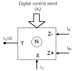
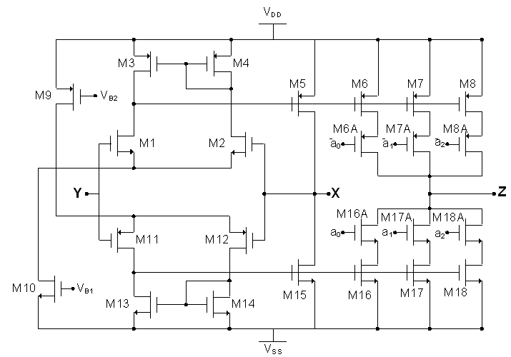
The digitally programmable Current Conveyor (DPCCII) is a versatile building block for analog signal processing applications[6]. The digitally programmable CCII with gain N is shown in Fig. 1 and its CMOS implementation is shown in Fig. 2.
Figure 1. DPCCII symbolic representation
(1)
(2)
Figure 2. CMOS implementation of a 3-bit DPCCII with current gain N[6]
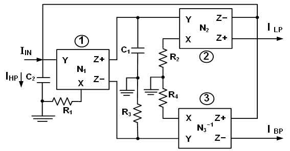
The power integer is m = 1 when the current gain is N, and m = −1 when the current gain is N−1. The proposed digitally programmable CM second-order filter is shown Fig. 3.
Figure 3. Proposed digitally programmable biquadratic filter
The circuit uses three DPCCIIs, two grounded capacitors and four grounded resistors. DPCCIIs ① and ② have a gain of N1 and N2 respectively, while DPCCII ③ has a gain of N3−1. Analysis of the proposed circuit using equation (1) yields the following transfer functions:
(3)
(4)
(5)
with
(6)
Equations (3) to (6) represents LP, BP and HP transfer functions respectively. The filter gain parameters are:
(7)
and the pole frequency and pole-Q are given as:
(8)
and
(9)
From equation (8) and (9) it is clear that the pole frequency and pole-Q can be independently controlled by varying digital control word. Assuming R1 = R2 = R3 = R4 = R, C1 = C2 = C and N1 = N2 = N, equations (8) and (9) reduce to:
(10)
(11)
Equation (11) shows that the pole-Q is directly proportional to the control word applied at DPCCII ③.

3. Effect of Non-Idealities and Parasitics

This section deals with the non-ideal analysis of the proposed circuit. A DPCCII is characterized by the following non-ideal transfer gains.
(12)
where βi is the voltage gain from Y and X terminal of DPCCII-i. α1i and α2i are the current transfer gains from X terminal to Z+ and Z− respectively where i = 1, 2, 3. Using equation (12) the ideal transfer functions of the second order filters given in equations (3), (4) and (5) yield the following non-ideal transfer functions.
(13)
(14)
(15)
Where
(16)
The non-ideal pole-frequency and pole-Q are expressed as:
(17)
(18)
From equations (17) and (18), it is clear that due to non-idealities of DPCCII, the pole frequency and pole-Q slightly deviate from ideal values. From equation (17), it is also clear that the active and passive sensitivities of pole frequency are found to be half in magnitude.
Next consider the effect of parasitics associated with DPCCII. In DPCCII port-Y parasitics are in the form of RY//CY, port-Z parasitics are in the form of RZ//CZ, and port-X parasitics in the form of series resistance RX. The modified transfer functions taking into account the above parasitics can be expressed as:
(19)
(20)
(21)
where
(22)
and
R1' = R1+ RX
R2' = R2+ RX
R3' = R3CP (since RP = R3RYRZ and CP = CZ+CY )
R4' = R4+ RX
C1' = C1+CZ+CY
C2' = C2+CY+2CZ
Since the parasitic capacitances CZ, CY are very small (in the range of fFs) and the port-Y parasitic resistances are very high (in the range of MΩ), the values of R1', R2', C1' and C2' are not significantly different from the values of R1, R2, C1 and C2, the value of ωo as found from (22) would not deviate much from the ideal value found from (8).
From (22), it is evident that the parasitic capacitance (CP) causes a third order term to appear in DP(s). The corner frequency due to the parasitic capacitance is given by
(23)
However, since the value of CP is small, the value of ωP would be very high,
(24)
and therefore no substantial change in the frequency response, considering the effect of parasitic, is thus observed due to the inclusion of the third-order term. Further, since CP is a very low value, its effect can be neglected from (19) to (22).

4. Design and Verification

The proposed filter, shown in Fig. 3, is verified by designing it for a variable pole frequency by selecting different control words. The supply voltages are taken as VDD = VSS = ± 0.75 V. Weights were set digitally by connecting the[a2, a1, a0] in Fig. 2 to a suitable voltage. For instance, to set a digital control word of[0 1 0], a3 was connected to VSS, a2 was connected to VDD and a0 was connected to VSS. The element values chosen are R1 = R2 = R3 = R4 = R =1 KΩ and C1 = C2 = C = 0.4 nF.
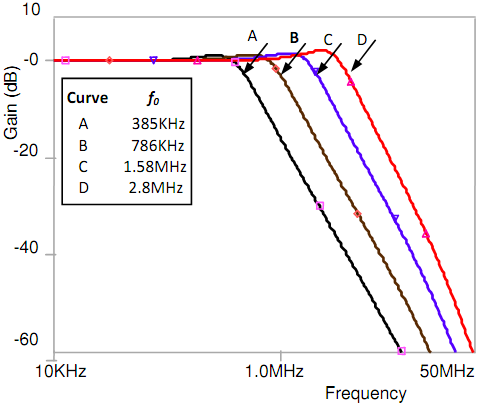
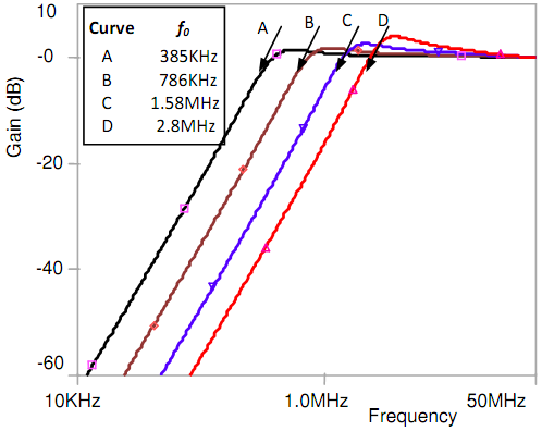
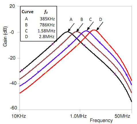
The filter responses are obtained by applying the same control words (N1=N2) to DCCCIIs ① and ②. Fig. 4 and 5 shows the low-pass and the high-pass responses. The band-pass response is depicted in Fig. 6. All the responses are obtained for the same set of control word N = 1, 2, 4, 7 and corresponds to curves A, B, C and D in Fig. 4 to Fig. 6. In addition, all the responses have a gain of unity. The simulated pole frequencies obtained are 385 KHz, 786 KHz, 1.58 MHz and 2.7 MHz while the corresponding theoretical frequency values are 397.8 KHz, 795.7 KHz, 1.59 MHz and 2.78 MHz respectively. As can be seen the simulated and theoretical frequencies are in close agreement.
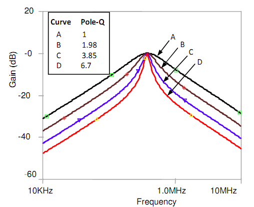
The variation of pole-Q by varying N3 (as 1, 2, 4 and 7) at 385KHz frequency is shown in Fig. 7 and the values of pole-Q obtained through simulation are 1, 1.98, 3.85 and 6.7 while the corresponding theoretical values are 1, 2, 4 and 7 respectively.
Figure 4. Tuning of LP filter function with digital control word
Figure 5. Tuning of HP filter function with digital control word
Figure 6. Tuning of BP filter function with digital control word
Figure 7. A Pole-Q variation with digital control word at 385KHz

5. Conclusions

The paper presents a current-mode biquadratic filter with digital control of filter parameters. The circuit is CMOS compatible and suitable for monolithic implementation by virtue of use of all grounded passive elements. Other features of interest are that the pole-frequency and pole-Q are independently digitally controlled, and low sensitivities of pole frequency (ω0n) with respect to active and passive components. Non-idealities of the active element are also considered along with the parasitics involved, so as to evaluate the performance of the proposed filter.

References

[1]  B. Wilson, “Recent developments in current conveyors and current-mode circuits”, IEE Proc. Circuits Devices Systems, vol. 137, No. 2, pp. 63–77, 1990.
[2]  H. Q. Elwan and A. M. Soliman, “Novel CMOS differential voltage current conveyor and its applications”, IEE Proc. Circuits Devices Systems, vol. 144, No. 3, pp. 195-200. 1997.
[3]  C. Toumazou, F. J. Lidgey and D. G. Haigh, “Analogue IC Design: The Current-Mode Approach”, IEE, York, UK, 1998.
[4]  S. Yan and E. S. Sinecio, “Low voltage analog circuit design techniques: A tutorial,” IEICE Trans. Analog Integrated Circuits and Systems, vol. E00–A, pp. 1-17, 2000.
[5]  H. Elwan, H. Alzaher, and M. Ismail, “A new generation of global wireless compatibility,” IEEE Circuits and Devices Magazine, vol. 17, No.1, pp. 2-19, 2001.
[6]  S. A. Mahmoud, M. A. Hashiesh, and A. M. Soliman, “Low voltage digitally controlled fully differential current conveyor,” IEEE Transactions on Circuits and Systems-II, vol. 52, pp. 2055-2064, 2005.
[7]  I. A. Khan, M. R. Khan, and N. Afzal, “Digitally programmable multifunctional current mode filter using CCIIs,” Journal of Active and Passive Electronic Devices, vol. 1, pp. 213-220, 2006.
[8]  T. M. Hassan and S. A. Mahmoud, “Low voltage digitally programmable band pass filter with independent control,” in IEEE Int Conference on Signal Processing and Communications (ICSPC 2007), Dubai, UAE, pp. 24-27, 2007.
[9]  T. M. Hassan and S. A. Mahmoud, “Fully programmable universal filter with independent gain-ω0-Q control based on new digitally programmable CMOS CCII,” Journal of Circuits, Systems, and Computers, vol. 18, No.5, pp. 875–897, 2009.
[10]  P. Beg, I. A. Khan, S. Maheshwari, and M. A. Siddiqi, “Digitally programmable fully differential filter,” Radioengineering, vol. 20, No.4, pp. 917-925, 2011.
[11]  I. A. Khan and A. M. Nahhas, “Reconfigurable voltage mode first order multifunctional filter using single low voltage digitally controlled CMOS CCII”, International J. Computer Applications, Vol. 45, No. 5, pp. 37-40, 2012.
[12]  I. A. Khan and A. M. Nahhas, “Current mode programmable analog modules using low voltage digitally controlled CMOS CCII”, International J. Computer Applications, vol. 48, No. 4, pp. 38-44, 2012.
[13]  I. A. Khan and A. M. Nahhas, “Reconfigurable voltage mode phase shifter using low voltage digitally controlled CMOS CCII”, Electrical and Electronic Engineering, vol. 2, No. 4, pp. 226-229, 2012.
[14]  A. M. Nahhas, “Reconfigurable current mode programmable multifunctional filter”, International J. on Recent Trends in Engineering and Technology, vol. 7, No. 2, pp. 88-91, 2012.
[15]  M. Z. Khan and M. S. Ansari, Digitally programmable voltage mode universal biquadratic filter, International J. Computer Applications, vol. 54, No. 16, pp. 26-31, 2012.
[16]  P. Beg, S. Maheshwari and M. A. Siddiqi, “Digitallycontrolled fully differential voltage- and transadmittance-mode biquadratic filter”, IET Circuits, Devices and Systems (To appear, 2013).
[17]  I. A. Khan and S. Maheshwari, “Simple first order all-pass section using a single CCII, International Journal of Electronics, vol. 87, No. 3, pp. 303-306, 2000.
[18]  I. A. Khan and M. H. Zaidi, “Multifunctional translinear-C current-mode filter,” International Journal of Electronics, vol.87, (9), pp. 1047-1051, 2000.
[19]  T. Tsukutani, Y. Y. Sumi, and N. Yabuki, “Versatile current-mode biquadratic circuit using only plus type CCCIIs and grounded capacitors,” International Journal of Electronics, vol. 94, No.12, pp. 1147-1156, 2007.
[20]  T. Tsukutani, Y. Sumi, S. Iwanari, and Y. Fukui, “Novel current-mode biquad using MO-CCCIIs and grounded capacitors,” in International Symposium on Intelligent Signal Processing and Communication Systems, 2005, pp. 433-43.
[21]  S. A. Mahmoud and E. A. Soliman, “Low voltage current conveyor based field programmable analog array”, Journal of Circuits, Systems, and Computers, vol. 20, No. 8, pp. 1677-1701, 2011.
[22]  T. L Floyd, “Electronic Devices Conventional Current Version”, Ninth Edition, Pearson, 2012.
[23]  http://www.anadigm.com-dynamically programmable Analog Signal Processor or Field Programmable Analog Array.