-
Paper Information
- Next Paper
- Paper Submission
-
Journal Information
- About This Journal
- Editorial Board
- Current Issue
- Archive
- Author Guidelines
- Contact Us
American Journal of Signal Processing
p-ISSN: 2165-9354 e-ISSN: 2165-9362
2012; 2(6): 154-157
doi: 10.5923/j.ajsp.20120206.01
Source Localization by Conjugated Delays Method Main Description of a New Process of Passive Localization
 Abstract
 Reference
 Full-Text PDF
 Full-Text HTML
Philippe Crumeyrolle
Umechanics, Umechanics R&D, 7500, Paris, France
Correspondence to: Philippe Crumeyrolle, Umechanics, Umechanics R&D, 7500, Paris, France.
| Email: |  |
Copyright © 2012 Scientific & Academic Publishing. All Rights Reserved.
The method of the combined delays is a passive tracking process. It is a triangulation method employed to locate the signal hearth, which can be, according to the application area, of acoustic or electromagnetic origin. This method is based on the process of the delays combination, (delays which result from the differences in distances between the source and the sensors of the reception station), which makes it possible to determine emission direction. By knowledge of angles measurements of the signal arrivals on the reception sensors of station, one completely determines the triangles, which establish the source position.
Keywords: Localization, Passive, Triangulation, Delay
Cite this paper: Philippe Crumeyrolle, "Source Localization by Conjugated Delays Method Main Description of a New Process of Passive Localization", American Journal of Signal Processing, Vol. 2 No. 6, 2012, pp. 154-157. doi: 10.5923/j.ajsp.20120206.01.
Article Outline
1. Introduction
- The purpose of goniometry is to estimate wave incidence angles. These waves may be electromagnetic or acoustic. Goniometers are made up of an antenna or network of antennas comprising several sensors configured in a given geometry, and a calculation algorithm. A radiogoniometer is a system capable of measuring the arrival direction of an electromagnetic wave with respect to a reference direction. The radiogoniometer samples an interpretation of the wave front of the electromagnetic wave over a network of several sensors to determine the arrival direction. The acoustic goniometer is a system that measures the arrival direction of sounds and thus estimates the direction of the emission source. Like the radiogoniometer, it is made up of an antenna configured in a geometry corresponding to the acoustic domain and a calculation algorithm. The localisation of sound sources by acoustic goniometry is based on a space-time process implemented in two steps. The temporal step extracts the arrival time of the signal or the differences in propagation times at the sensors of an antenna. The second step determines the direction of arrival according to the spatial configuration of the antenna.For both the electromagnetic and acoustic domains, these passive instruments use sensors that cover a very wide spectrum. They have the advantage of being discreet, unlike radar or sonar which emit pulses
2. Localisation by Conjugated Delays
- Localisation by conjugated delays is a goniometric method based on the conjugation of propagation delays. This method is independent of the application field. When, at an instant tunknown, an event is triggered by a source (electromagnetic or acoustic), the wavefront propagates up to the station receivers, which record the signals corresponding to the emitted signal, delayed by the propagation times. A specialised circuit measures the arrival instants of the signal for each antenna sensor with respect to its internal clock. These measurements are processed by the microprocessor that conjugates the delays and determines the direction and range of the signal source. Regardless of whether the field of application is electromagnetic or acoustic, this method requires an antenna of specific geometry
3. Antenna Configuration
- The antenna is an assembly of base elements, or in short “base”. Each base comprises three omnidirectional receiver transducers that are aligned and equally spaced. In other words, a base comprises omnidirectional receivers equipping the ends and centre of a straight-line segment. See figure 1 below.The antenna is built with bases of length, configuration and number suited for the intended use. Locating a source in a three-dimensional propagation space requires that the antenna be made up of at least three bases that are not aligned and which are not all positioned in the same plane, or of two non-aligned bases and an additional receiver, external to the plane defined by the two bases. The addition of this receiver allows the identification of the part of the space the signal originates from. This elementary antenna is static and none of its components requires mechanical or electronic orientation.
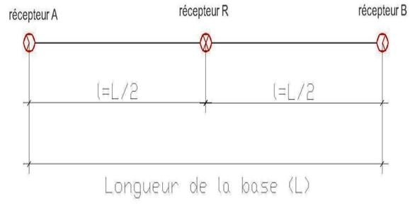 | Figure 1. Schema of a base |
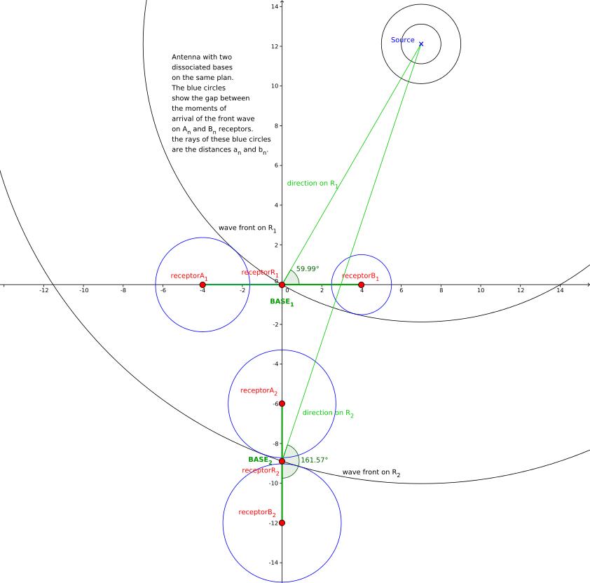 | Figure 2. wave front crossing an antenna two bases made |
4. Organisation of Data
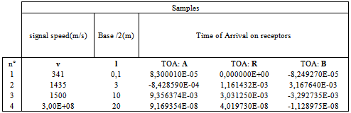
- The data used by this method can be classed into the following four main groups.Construction data: They determine antenna geometry by defining the spacing between the receivers of each base and the configuration of the bases with respect to each other. (Antenna bases may be of different lengths and any configuration).Assigned data: For each antenna base, three different symbols or letters are assigned to its three receivers and with which an index is associated to distinguish the base. As an illustration, the indexed letters An and Bn can be assigned to the sensors at the ends of the base, the indexed letter Rn assigned to a receiver positioned in the centre of basen. The distance between receivers An and Rn is equal to the distance between the receivers Rn and Bn, with this length between two base receivers called ln.Physical data: This description of principle does not take account of the physical variables required for a practical application, keeping only signal propagation speed. Here, the propagation speed is considered constant. Signal speed is represented by v.Acquisition data: once the signal of the source to be located has arrived at each antenna receiver, the station’s acquisition system produces a report for the arrival times on the receivers An, Rn and Bn for each base. These arrival times are called: DAn on An, DRn on Rn, DBn on Bn.The table below shows acollection of TOA sampled from acoustic or electromagnetic source
5. Method
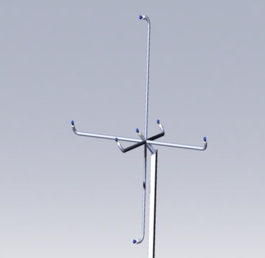 | Figure 3. Illustration: Antenna of acoustic direction finder. This antenna made with three bases, their central sensor is common |
|
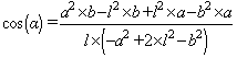 | (1) |
6. Conclusions
- The passive detection and localization has gained much importance for both military and civilian applications. It has several advantages over active methods, which make it a very viable alternative and sometimes indispensable. The techniques currently in use implements following principles.The radiogoniometry of amplitude using directly the diagram of radiation of the antenna.The radiogoniometry Watson-Watt or with antennas Adcock.The radiogoniometry Doppler, obtained by rotation of an omnidirectional antenna around a center with a rotation speed .The radiogoniometry by interferometry. The radiogoniometry of amplitude and phase based on the high-resolution vectorial correlation or not.While, the passive acoustic localization systems can be subcategorized into two groups. Those using the indirect method determine position by a step of estimating time delays between pairs of sensors (TDOA, time differences of arrival) and then step that determines the position based on these delays. Those using the direct method determine the position of the source in one step, by various techniques of beamforming. The main difference with existing techniques is that LCD method, can universally, be implemented in the field of electromagnetic or acoustic applications. This new principle responds to the needs of applications that are based on the capacity of systems to deliver location information instantly and precisely. Regardless of the domain and environment of use, the simplicity of the antenna and the processing resources allow the construction of robust systems that provide determining advantages both in terms of technology and cost.