Mojdeh Mahdavi , Mohammad Amin Amiri
Department of Electronics, Shahr-e-Qods Branch, Islamic Azad University, Tehran, Iran
Correspondence to: Mojdeh Mahdavi , Department of Electronics, Shahr-e-Qods Branch, Islamic Azad University, Tehran, Iran.
| Email: |  |
Copyright © 2012 Scientific & Academic Publishing. All Rights Reserved.
Abstract
Utilizing the DFT, the DHT, the DCT or the DST is an obvious choice in signal processing domain. This paper describes the implementation of a semi-unified high performance coprocessor of transform length '8' for the synchronous design in XC3S1400AN-4FG484 FPGA device of Xilinx Company. The operating frequency of 20 MHz is achieved. The paper presents the trade-offs involved in designing the architecture, the design for performance issues and the possibilities for future development.
Keywords:
Coprocessor, Discrete Transforms, Implementation
Cite this paper:
Mojdeh Mahdavi , Mohammad Amin Amiri , "Design and Implementation of a Semi-Unified High Performance Signal Processing Coprocessor", American Journal of Signal Processing, Vol. 2 No. 1, 2012, pp. 1-4. doi: 10.5923/j.ajsp.20120201.01.
1. Introduction
Memory based Field Programmable Gate Arrays (FPGAs) have the advantage of real-time in-circuit re-configurability as opposed to other gate arrays of similar gate density. This advantage translates into unlimited, in-circuit flexibility, re-configurability and reliability, facilitating prototyping of complex electronic designs[1]. The high capacity and performance that FPGAs have achieved in recent years allow them to accelerate digital signal processing (DSP) tasks. FPGA devices have been used to implement Custom DSPs since the beginning of this decade[2]. Usually, FPGAs are used as VLSI replacement on low volume production or prototyping devices which are to be eventually implemented as ASICs. Their 100% testability and the possibility of achieving a high degree of fault coverage makes them increasingly attractive for complex designs with multiple (and of course limited) iterations on their design cycles[1]. The FPGA devices have benefited from the improvements in VLSI technology, leading to higher speed and capability as well as lower power consumption[2].The discrete transform algorithms are very well known and due to their versatility and very simple hardware implementation are widely used in VLSI digital signal processing systems. The discrete Hartley transform (DHT) is similar to the DFT, with the only difference that it deals only with real computation. The discrete cosine transform (DCT) has long been used in image and speech processing. The JPEG standard till JPEG2000 used the DCT as the basis function. The discrete sine transform (DST) is useful for spectrum analysis, data compression, speech processing, biomedical signal processing and in many other applications. These basic signal processing transforms are required in almost all the phases of image and signal processing and cover a large range of biomedical signal and image processing, for various imaging techniques and spectral analysis of the signals[4].A number of architectures are proposed for the realization of these transforms[2-7]. However, a unified architecture, which can compute all these transforms, can serve the purpose of a general DSP chip, and therefore a unified architecture has been adopted to obtain all the transforms in a single FPGA chip. The basic structure of all the transforms, DFT, DCT, DHT and DST, are almost equivalent and this property has been exploited in the design of the unified architecture.
2. Discrete Transforms
This Section presents the transforms in detail and the possibility of their implementation as the basic processing elements. For a real sample sequence x(n), where n is (0,1,..., N-1) the discrete transforms which are the DFT, the DHT, the DCT and the DST, can be defined as:DFT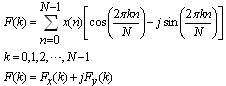 | (1) |
DHT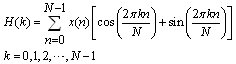 | (2) |
DCT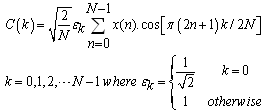 | (3) |
DST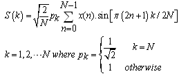 | (4) |
2.1. DHT based on Direct Algorithm
Let  be an 8-length Hartley Transform pair. The corresponding formulation in matrix form is
  where [T] is an 8x8 cas (cosine and sine) matrix [6].Let
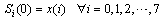 | (5) |
The transform matrix for the 8-DHT is therefore: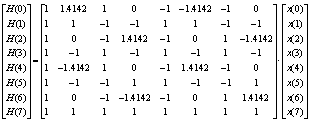 | (6) |
We start by remarking initially that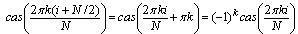 | (7) |
Which follows from the addition of arcs formula:Where  is the complementary cas function andClearly, modules of components on the 2nd column are identical to the corresponding elements at the 6th column; the same is true for the 3rd and 7th column. We can thus consider new variables
 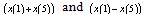 instead of x(1) and x(5),
 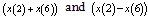 instead of x(2) and x(6) , and so on.
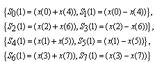 | (8) |
The first-order pre-additions as defined above always yield at least a half of vanishing elements in the new transform matrix. Although such an implementation requires only two multiplications, we may go further and combine other columns.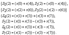 | (9) |
Therefore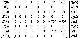 | (10) |
2.2. An Algorithm for the DFT Implemented by DHT
According to the definition of DFT and DHT the DFT data Sequence is given by the following relation: | (11) |
 | (12) |
2.3. Fast Cosine Transform based on Direct Algorithm
According to the definition of DCT, for a given data sequence , the DCT data sequence
  is given by (equation (3)). The discrete Cosine Transform is defined as a matrix multiplication which is illustrated below[7-8].
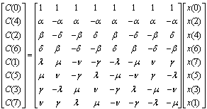 | (13) |
Where 
 and
and 
2.4. An Algorithm for the DST Implemented by DCT
In this part a method of composing the discrete sine transform from the discrete cosine transform is demonstrated. Let x (n): n 0, 1, 2,}, N-1, be a sequence of N data values[9]. Substituting m N k; k 1, 2… N into the discrete cosine transform (equation (5)), results in: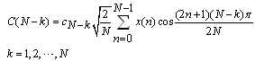 | (14) |
Since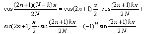 | (15) |
Therefore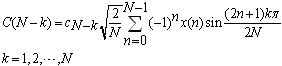 | (16) |
Let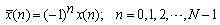 | (17) |
And  be the discrete cosine transform of sequence x(n) then:
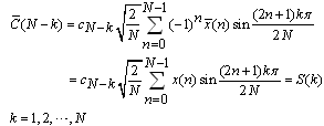 | (18) |
Where, S(k) is the discrete sine transform (DST) of the sequence x(n) . Therefore, the procedure for obtaining the sine transform of the sequence x(n) is composed of three steps.1. Change the signs of all odd numbered data to the opposite sign to form a new sequence . (Notice that the sequence number is counted from zero).2. Compute the discrete cosine transform on the sequence
 .3. By reversing the sequence order of data which were produced by step 2, the discrete sine transform of the sequence x(n) is obtained.This procedure may be represented in the form of matrix multiplication. Let [Sn] and [Cn] be the discrete sine and cosine transforms of order N, respectively [13-15]. Then
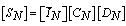 | (19) |
Where is the opposite diagonal identity matrix, and [Dn] is the odd sign changing matrix defined as:
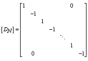 | (20) |
3. Coprocessor Architecture
3.1. DCT_DST Block
The DCT block is first implemented according to the direct Algorithm (equation (13)) and then we have used this DCT block to implement the DCT_DST block (equation (19)). Figure. 1 illustrates the proposed architecture for DCT_DST block. If the "S" input signal has the logic value of zero, the DCT transform would be applied on the input data vector and if the "S" input signal has the logic value of one, the DST transform would be applied on the input data vector.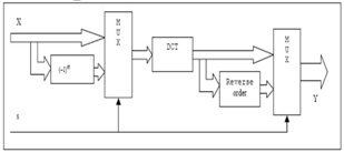 | Figure 1. Block diagram for proposed DCT_DST architecture |
3.2. DHT_DFT Block
First, the DHT block is implemented according to the Direct Algorithm using its matrix form in (equation (10)) and then it is used to implement the DHT_DFT block (equations (11), (12)). Figure. 2 is our proposed architecture. The hardware is extracted from this data flow diagram. If the "S" input signal has the logic value of zero, the DHT transform would be applied on the input data vector and if the "S" input signal has the logic value of one, the DFT transform would be applied on the input data vector. The "I" signal is also used to select the real or imaginary part of the DFT transform. This signal is just for understanding the block diagram and is ignored in the top module.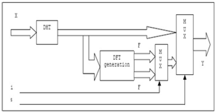 | Figure 2. Block diagram for proposed DHT_DFT architecture |
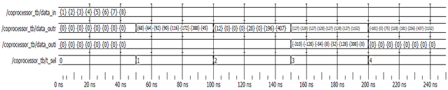
Figure. 3 shows the synthesized block diagram of the Coprocessor. Figure 4. illustrates the simulation result of this module. During this simulation all of the four transforms of this coprocessor have been applied to an eight-bit data input.If the "T_SEL" signal has the hexadecimal value of "00", the outputs will be zero. Having the value of "01", the "T_SEL" signal will lead the DST transform to the output.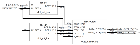 | Figure 3. Synthesized circuit of the Coprocessor |
 | Figure 4. Simulation result of the Coprocessor |
The DCT transform will appear on the output when the "T_SEL" signal has the value of "02". The values of "03" and "04" will lead the DFT and DHT transforms on the output, respectively.
3.3. Implementation Results
The whole architecture including the computation and data path is modelled at Register Transfer Level in VHDL, simulated and tested by a test bench using ModelSim simulator and implemented in XC3S700An-4FG484 FPGA device of Xilinx Company. The Simulation result of the proposed coprocessor has been shown on Figure 4.The Hardware description of this architecture for DCT, DST, DHT and DFT implementations of transform length '8' was synthesized using Xilinx Series FPGA tool (ISE) and mapped on the XC3S700An-4FG484 FPGA chip. In the 8-bit coprocessor implementation, the worst delay time is about 48 ns and thus a frequency of 20 MHz is achieved. The routed IP takes total of 3426 Slices which is 58 percent of the chip. The total number of I/Os used in the design is 328 which are 88 percent of the total I/Os of this chip.
4. Conclusions
This paper has proposed an efficient mapping on FPGA of a common Coprocessor. The DFT algorithm is implemented by DHT, which is based on Direct Algorithm. The Direct fast DCT algorithm is presented and then a method of computing the discrete sine-transform from the discrete cosine transform is demonstrated. For the future work we can implement this coprocessor using DCT as the base transform for implementing other transforms to obtain more surface reduction.
References
| [1] | J. Davidson, "FPGA Implementation of a Reconfigurable Microprocessor", IEEE Custom Integrated Circuits Conference, p.p.:3.2.1-3.2.4, 9-12 May 1993. |
| [2] | Javier Valls Martin Kuhlmann Keshab K. Parhi, "Efficient Mapping Of CORDIC Algorithms On FPGA" IEEE Workshop on Signal Processing Systems, p.p.336-345, 11-13 Oct. 2000. |
| [3] | B.Das, S.Banerjee, "Unified CORDIC-based chip to realize DFT/DHT/DCT/DST", IEE Proc. Comput. Digit. Tech., Vol. 149, No. 4, July 2002. |
| [4] | A.S Dhar, S. Banerjee, "An array architecture for fast computation of discrete hartley transform", IEEE Trans. Circuits Syst., Vol. 38, No. 9, pp. 1095-1098, 1991 . |
| [5] | Angarita, F.; Perez-Pascual, A.; Sansaloni, T.; Vails, "Efficient FPGA implementation of CORDIC algorithm for circular and linear coordinates", International Conference on Field Programmable Logic and Applications, p.p.535-538, 24-26 Aug. 2005. |
| [6] | A.C. Erickson, B.S. Fagin, "Calculating the FHT in hardware", IEEE Trans. Signal Processing, Vol.40, p.p.1341-1353, June 1992. |
| [7] | H. EL-Bannai, A. A. EL-Fattah, W. Fakhr, "An efficient implementation of the 1D DCT using FPGA technology", ICM 2003, Dec. 9-1 1, Cairo, Egypt, 2003. |
| [8] | N.Ahmed, T.Natarajan, K.R.Rao, "Discrete cosine transform", IEEE Transactions on Computers, Vol. C-23, Issue1, p.p. 90-93, Jan. 1974. |
| [9] | J. Astola, D. Akopian, "Architecture-oriented regular algorithms for discrete sine and cosine transform", IEEE Trans. Signal Processing, Vol. 47, p.p.1109-1124, Apr. 1999. |
 Abstract
 Reference
 Full-Text PDF
 Full-Text HTML