Rishvanth 1, D. Valli 2, K. Ganesan 2
1B.Tech in Electronics and Communication Engineering, VIT University, Vellore
2TIFAC-CORE in Automotive Infotronics, VIT University, Vellore, 632014, India
Correspondence to: K. Ganesan , TIFAC-CORE in Automotive Infotronics, VIT University, Vellore, 632014, India.
| Email: |  |
Copyright © 2012 Scientific & Academic Publishing. All Rights Reserved.
Abstract
Today’s vehicles include a complex symbiosis of intelligent electronic systems and integrated mechanical structures. In-vehicle networks provide an efficient method of communication between the various electronic components in an automobile. The communication protocols discussed in this paper are Local Interconnect Network (LIN), Controller Area Network (CAN) and FlexRay. LIN is used in low speed applications, CAN are used in medium speed applications and FlexRay is used in high speed applications. A gateway is a network node used to transfer data from one communication protocol to another. Vector CANoe is an all-round tool for the development, testing and analysis of entire ECU networks and individual ECUs. Vector CANoe uses a 3-phase development process that assists the user from the planning of the distributed system to the implementation of it. In this paper we have explained how to create 3 different networks (LIN, CAN and FlexRay) and also designed a gateway so that the messages can be transferred between different communication protocols. To start with we tested the design of the gateway using simulations and subsequently we have connected the necessary hardware and diagnosed the messages.
Keywords:
LIN, CAN, FlexRay, Gateway, Diagnostics
Cite this paper:
Rishvanth , D. Valli , K. Ganesan , "Design of an In-Vehicle Network (Using LIN, CAN and FlexRay), Gateway and its Diagnostics Using Vector CANoe", American Journal of Signal Processing, Vol. 1 No. 2, 2011, pp. 40-45. doi: 10.5923/j.ajsp.20110102.07.
1. Introduction
In an automobile the number of electronic components is increasing exponentially. In the automobiles manufactured today number of electronic sensors and actuators are very high so that point-to-point communication is not possible. The main reasons being the large number of wires needed to connect all the components, non-availability of space and in case of a failure the fault detection will be extremely difficult. All these factors lead to the development of a distributed system in which all the components are connected to various bus and the devices communicate with each other using standardized automotive protocols. LIN, CAN and FlexRay are some of the protocols used in automobiles today for communicating between the various components. A gateway is designed to transfer messages between different communication protocols[1,2].Vector CANoe is a tool that assists in the development of the In-vehicle Network using various protocols. This tool allows the user to simulate the various networks and the gateway before the actual development process. During the development process the tool can be used to integrate the virtual and the physical bus for the simulation of the remainder of the bus. After the development CANoe can be used to analyze the physical network for bus statistics.The in-vehicle networking concepts are nowadays used in safety systems such as collision avoidance systems[3]. Hybrid Network, provides not only the communication functions of different in-vehicle subsystems, but also the controlling policy, authentication and human-computer interactions, and can improve the safety and comfort of driving[4]. The various control modules of a vehicle such as Engine Control Modules, Transmission Control Modules and Body Control Modules etc. usually communicate with each other, in real time, helping in the operation of the vehicle[5,6]. The past few years have seen a large growth in the number and type of communication buses used in automobiles, trucks, construction equipment, and military, among others[7]. Recently FPGA based networking are used for high data rate and reliable in-vehicle communication[8]. The simulation environment is the initial step to design cost effective, flexible and deterministic in-vehicle networks suitable for use in the next generation of vehicles[9]. People started using switch-based network architecture and analyze the various routing schemes in terms of their performance in in-vehicle networks[10].The paper is organized as follows: In section 2, we introduce the various protocols such as LIN, CAN and FlexRay in sections 2.1, 2.2 and 2.3 respectively. Subsequently in section 2.4 we introduce the Vector CANoe tool which is used for the development of the present system. In section 3, we talk about the three phase development model used for the present work. The various steps involved in the design of network using Vector CANoe are explained in detail in section 4. In the final section 5, we derive our conclusions.
2. Concept of LIN, CAN and FlexRay
2.1. LIN
LIN is a low speed asynchronous bus offering a data rate of upto 20kbps; it is used in the non-critical applications. It is a low cost and single wire communication network and it is implemented using the UART/SCI interface in microcontrollers[11,12]. A LIN network uses master-slave architecture as shown in Fig.1 below.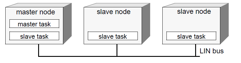 | Figure 1. Master-Slave Architecture |
The LIN master sends a frame header and the LIN slave responds to it by sending a frame. It consists of one master node and several slave nodes. The master node performs the master task in addition to the slave task. The LIN frame consists of a frame header and response as shown in Fig. 2 below. The header contains the response identifier. One slave node responds to the identifier and it transmits the frame response and several slave nodes respond to the identifier and receive the frame response. The response consists of a data field and a checksum field. 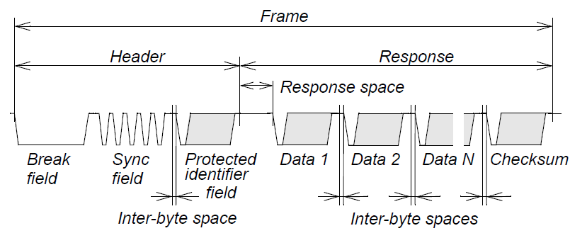 | Figure 2. LIN Frame |
2.2. CAN
CAN is a medium speed asynchronous bus offering a data rate of up to 1Mbps, it is used mainly in the sensor based applications. It uses an unshielded twisted two-wire line as the physical transmission medium and it is implemented using CAN controller interface in a microcontroller. CAN network is based on a combination of multi-master architecture and line topology. Any CAN node can place a message on the CAN bus[13]. The transmission of a CAN message does not follow any predetermined time sequence rather it is event-driven. The bus access is initiated when the bus is idle, by bus arbitration process, by which it is ensured that higher priority information is gaining the bus access[14].A CAN data frame is used for transmitting data and it can transmit a maximum payload of 8 bytes. This frame includes the message address, Data Code Length (DLC), checksum and the acknowledgement field. If a standard identifier is used, the message identifier consists of 11 bits (as shown in Fig.3 below) and if extended identifier is used it consists of 29 bits. All CAN messages are broadcast to every node, thus node-specific filtering is required to receive the required messages.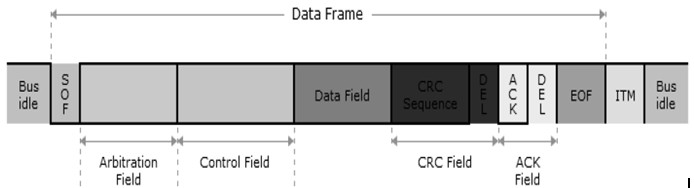 | Figure 3. CAN Frame Format |
2.3. FlexRay
FlexRay is a serial communication technology offering a data rate of up to 20Mbps designed for safety-critical areas and in x-by-wire applications in an automobile. FlexRay uses two channels for communication, namely Channel A and Channel B, each consisting of a pair of wires. FlexRay communication is not restricted to any specific topology. To minimize the risk of failure, FlexRay provides for the redundant layout of the communication channels, time determinism of message transmission and error tolerance. Each of the channels may be operated simultaneously at 10 Mbps or the redundant channel may be used to increase the data rate to 20 Mbps. FlexRay network supports bus, star and hybrid network topologies[15,16].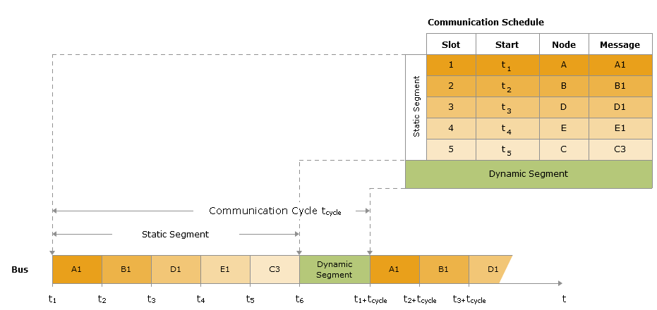 | Figure 4. Principle of bus access |
A FlexRay communication cycle consists of Static slots and Dynamic slots as shown in Fig.4 above. Static slots use the TDMA method (Time Division Multiple Access) and Dynamic slots use FTDMA method (Flexible Time Division Multiple Access) for bus access. Static slot consists of equal lengths and during the communication cycle each FlexRay node is guaranteed access to the communication bus according to the schedule. Then the communication cycle consists of dynamic slots for messages in a FlexRay cluster that should not be transmitted on a fixed time schedule but on an event driven basis. Being Time division multiple access based communication scheme, FlexRay network startup is performed on all nodes synchronously. A node called Coldstart node initiates startup process. Maximum three nodes are configured as Coldstart nodes and at least two fault-free nodes are needed for startup process. The leading Coldstart node send collision avoidance symbol to begin the startup process, it is then joined by other Coldstart nodes and afterwards by all other nodes. The Clock synchronization is achieved by calculation of offset and rate correction value to compensate frequency and phase differences that occur among Electronic Control Units[16]. A FlexRay frame consists of a header, payload and a trailer. The header consists of 40 bits and it contains the indicators, identifiers, Payload length, Header CRC and cyclic count. The payload can consist of 0-254 bytes and the payload length shows the length of the payload. The payload consists of the static and the dynamic segment. To protect the payload CRC method is used. The CRC is calculated with the header, payload and the CRC polynomial defined in the specification. The CRC sequence is appended to the payload as a trailer as shown in Fig.5 below.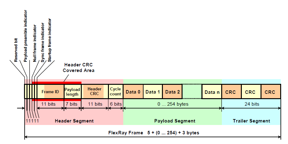 | Figure 5. FlexRay Frame Format |
2.4. Vector CANoe
CANoe is a universal development, test and analysis environment for serial bus systems, which is made available to all project participants over the entire development process. The system is supported in functional distribution, functional checking and integration of the overall system. It is used to obtain an ideal test environment by simulation of the remainder of the bus and environment[17].
3. Three Phase Development Model
The development process using Vector CANoe is based on a multiple phase model which differentiates between three development stages:
3.1. Phase 1: Requirement Analysis and Design of the Network System
First, the user responsible for design distributes the overall functionality of the system among different network nodes and refines the design to the level of the network node as shown in Fig.6 below. This includes defining messages and selecting the baud rate of the bus. Finally the bus behaviour of individual network nodes must be specified, e.g. in the form of cycle times or more complex protocols. Then this information can be evaluated first by the simulation tool to provide initial estimates of bus load and the latency times to be expected at the prescribed baud rate. Afterwards, this specification can also be utilized for testing in subsequent phases. 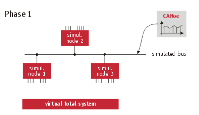 | Figure 6. Phase 1 |
For a more accurate study, a dynamic functional model of the overall system is created. This involves specifying the behaviour of the network nodes with regard to input and output variables and the messages to be received and transmitted. Especially useful here is an event-driven model with a procedural description of behaviour. For example, the model may describe how - after receiving a message (Event) - the received data are to be further processed (procedural) and how the result is to be output as a control variable. The user must also specify the input variables to the simulation tool, so that the time behaviour of network nodes and the accumulation of messages can be simulated. The results of the simulation serve to validate the design and can later be used as a reference after implementation.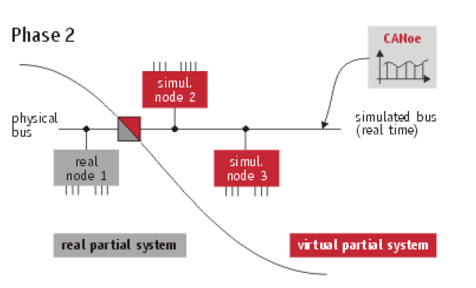 | Figure 7. Phase 2 |
3.2. Phase 2: Implementation of Components with Simulation of Remainder of the Bus
After the first phase has been completed the design and development of individual network nodes is usually performed by all participants, independently and in parallel as shown in Fig.7 below. The models for the other network nodes can now be used to simulate the remainder of the bus for testing of a developed network node. The tool requires an interface to the real bus. For this, it must be able to conduct the simulation in real time.
3.3. Phase 3: Integration of the Overall System
In this last development phase all real network nodes are connected to the bus in a step-by-step manner as shown in Fig.8 below. To accomplish this it must be possible to "disconnect" the models one-by-one in the simulation of the remainder of the bus. The tool serves increasingly as an intelligent analysis tool which observes the message traffic between the real network nodes on the bus and compares the results with the specified requirements. 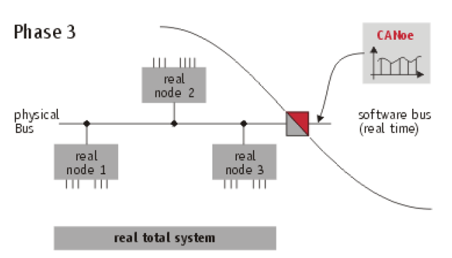 | Figure 8. Phase 3 |
4. Steps to Design a Network using Vector CANoe
The following were used in creating and analyzing a network using Vector CANoe:• Step 1: We need to create a database that describes the entire network.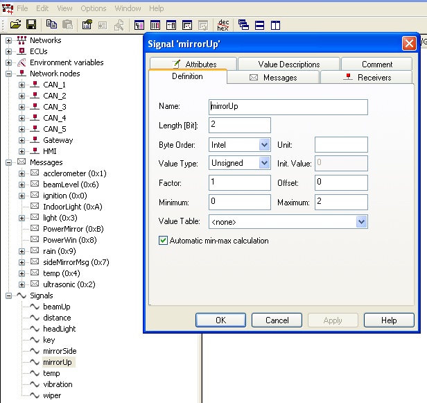 | Figure 9. Vector CANdb++ Editor |
The database is created using the software Vector CANdb ++ Editor for a CAN network. This software creates a .dbc file as shown in Fig. 9 below. For a LIN network the database is created using the software Vector LIN File Editor. This software creates a LIN Description File (LDF) as shown below in Fig.10 and for a FlexRay Network the database is created using FIBEX Explorer software. This software creates a FIBEX file (.xml) as shown in Fig. 11 below.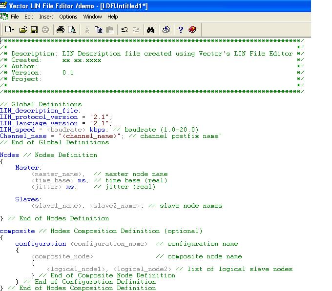 | Figure 10. Vector LIN File Editor |
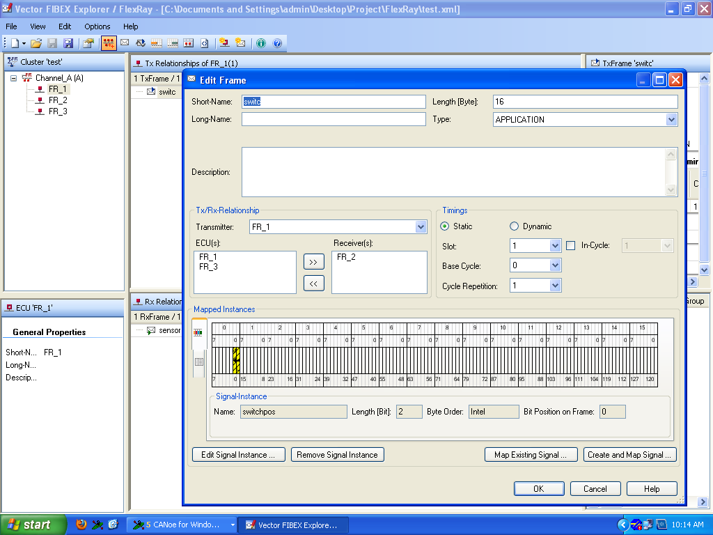 | Figure 11. FIBEX Explorer |
• Step 2: We can create necessary panels to describe the node’s peripherals now. Panels in Vector CANoe are created using the software Panel Editor. This is shown in Fig.12 below.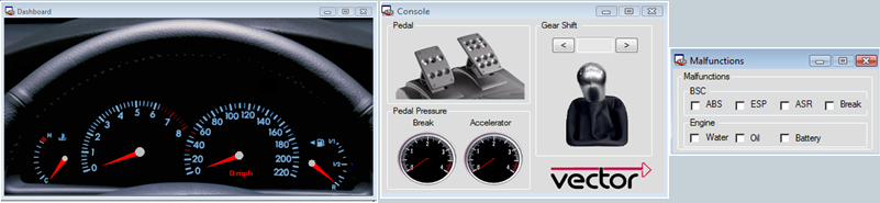 | Figure 12. Panels in Vector CANoe |
• Step 3: Now one has to create network nodes. Network nodes are created in the simulation window of Vector CANoe. This is a separate simulation window for each of the network i.e. a separate window for CAN, LIN and FlexRay network. Figs.13 and 14 below show the creation of CAN and FlexRay networks.• Step 4: One writes the CAPL programs for each node.The universal applicability of CANoe results in large measure from its user programmability. The Communication Access Programming Language CAPL is a C like programming language, which allows us to program CANoe for individual applications. Thus the data traffic of all remaining stations can be simulated with the help of CAPL. We can also write programs for problem-specific analysis of data traffic with CAPL, or we can program a gateway – a connecting element between two buses – to exchange data between different CAN buses. 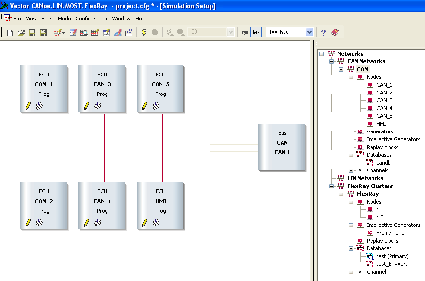 | Figure 13. Network Nodes for CAN Network |
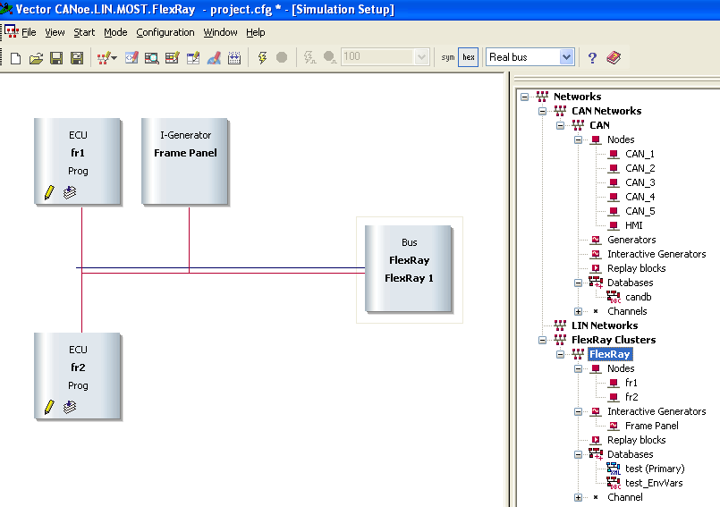 | Figure 14. Network nodes for FlexRay network |
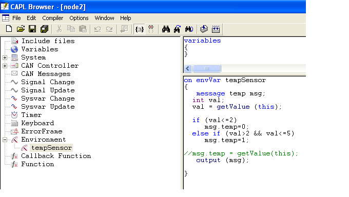 | Figure 15. CAPL Browser |
CAPL nodes are inserted in the data flow plan as function blocks. Event procedures serve as inputs in CAPL. These procedures can react to external events (e.g. the occurrence of specific messages). We can send messages by calling the function output(). These language tools and symbolic access to the various variables in the database make it possible to create simple prototypical models of nodes. The event procedures can be edited in the user-friendly browser as shown in Fig.15 below.• Step 5: Finally one can simulate and analyze the results.After the hardware implementation of the networks, the busses are connected to Vector CANoe to view the messages being transferred on the bus and it analyzes the bus for error frames, bus load, etc. For connecting the CAN bus to Vector CANoe a hardware called the CANcaseXL is used. This hardware does not need any power supply and the channel 1 of it connects to the CAN bus as shown in Fig.16 below.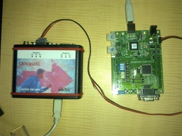 | Figure 16. Vector CANcase XL |
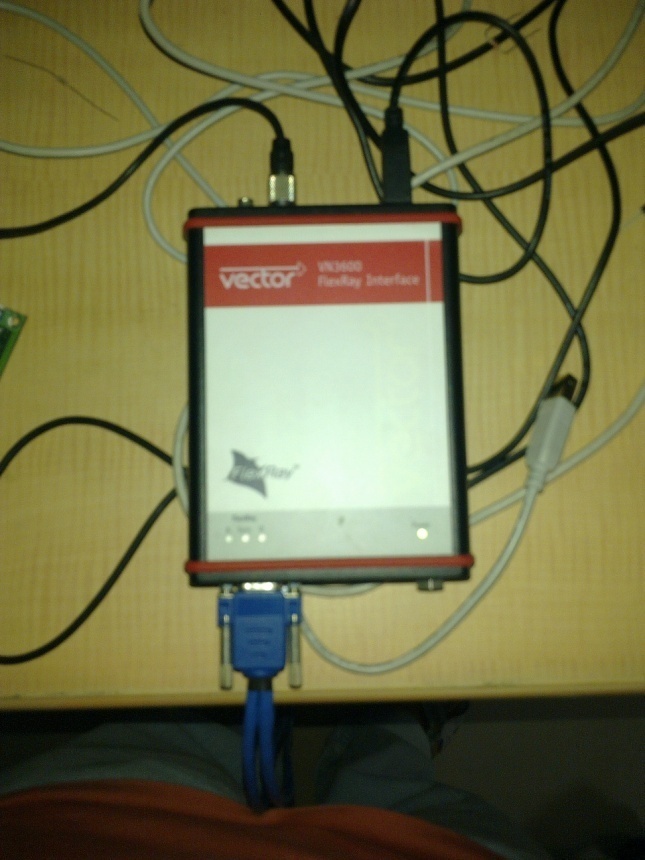 | Figure 17. Vector VN3400 FlexRay Inter |
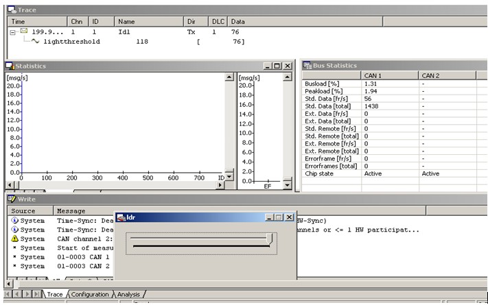 | Figure 18. Vector Diagnostics Window |
For connecting the FlexRay bus to Vector CANoe a hardware called the Vector VN3400 FlexRay Interface is used. It needs an external power supply and both the channels of the FlexRay bus can be connected using the same hardware as shown in Fig.17. The Figure 18 above shows the diagnostics window of Vector CANoe. All the messages being transferred on the network busses can be seen on the Trace window. The statistics window shows the graph of the messages being transferred per second. The Bus Statistics window shows the current bus load, peak load, number of standard, data and error frame. The write window displays any diagnostic messages.
5. Conclusions
This paper explains the concepts of the various protocols used in In-Vehicle networks and with the help of the analysis tool – Vector CANoe all the protocols are tested and diagnosed using the three phase development process. The gateway is also designed using this software. Finally, all the networks were tested and the required modifications were made using CANoe until the requirements were met.
ACKNOWLEDGEMENTS
This work forms part of the Research and Development activities of TIFAC-CORE in Automotive Infotronics located at VIT University, Vellore – 632 014. The authors would like to thank the TIFAC-CORE for providing the necessary facilities (both hardware and software) to carry out this work successfully.
References
| [1] | Li, G-X, Qin, G-H, Liu, W-J, Zhang, J-D, “ Design and Implementation of Vehicle Gateway Based on CAN Bus” Journal of Jilin University. Information Science Edition. Vol. 28, no. 2, pp. 166-171. Mar 2010 |
| [2] | Schmidt, E.G.; Alkan, M.; Schmidt, K.; Yüru klu, E.; Karakaya, U, “Performance evaluation of FlexRay/CAN networks interconnected by a gateway “IEEE Industrial Embedded Systems (SIES), 2010 International Symposium, PP 209 - 212 July 2010 |
| [3] | William D. Horne, Edward P. Olechna, and Ronald Brunot, “Application of In-vehicle data buses for collision avoidance systems”, IEEE Conference on Intelligent Transportation System, ITSC’97, pp.433-438, 1997 |
| [4] | Zhaohui Wu, Qing Wu, Jie Sun, Zhigang Gao, Bin Wu and Mingde Zhao, “ScudWare: A Context-Aware and Lightweight Middleware for Smart Vehicle Space”, Lecture Notes in Computer Science, Volume 3605/2005, 266-273, 2005 |
| [5] | B.K.Ramesh, K. Srirama Murthy, “In-vehicle networking”, Dearborn electronics. “http://www.deindia.com/images/downloads/whitepapers/In-Vehicle_Networking.pdf” |
| [6] | Christopher A. Lupini, “In-Vehicle Networking Technology for 2010 and Beyond”, Delphi Corporation, SAE International, 2010-01-0687, 2010 |
| [7] | Junshan Gao, Yixiang Zhang, Bo Wu, ”The design of a vehicle network CAN/LIN gateway based on ARM” IEEE International Conference on E-Product E-Service and E-Entertainment (ICEEE), November 2010 |
| [8] | Sergio Saponara, Esa Petri, Marco Tonarelli, Iacopo Del Corona, Luca Fanucci, “FPGA-based Networking Systems for High Data-rate and Reliable In-vehicle Communications”, Design, Automation & Test in Europe Conference & Exhibition, DATE '07, pp.1-6, 2007 |
| [9] | Shane Tuohy, Martin Glavin,Ciarán Hughes, Edward Jones, Liam Kilmartin, “An ns3 based Simulation Testbed for In-Vehicle Communication Networks”,www.eee.nuigalway.ie/Research/car/documents/stuohy_ukpew2011.pdf |
| [10] | Shuhui Yang, Wei Li, and Wei Zhao, “On Routing Schemes for Switch-Based In-Vehicle Networks”, IEEE Conference on Computer Communications Workshops (INFOCOM WKSHPS), pp.678-683, 2011 |
| [11] | K. Y. Cho, C. H. Bae, Y. Chu and M. W. Suh, “Overview of Telematics : A system architecture approach”, International Journal of Automotive Technology, Vol. 7, No. 4, pp. 509- 517 (2006) |
| [12] | LIN protocol specification, Version 2.1, 2006. “http://www.lin-subbus.org” |
| [13] | Karl Henrik Johansson, Martin Torngren, Lars Nielsen, “Vehicle Applications of Controller Area Network”, Handbook of Networked and Embedded Control Systems, Springer Verlag, Boston, 2005 |
| [14] | Bosch. CAN Specification, Version 2.0, 1991. “http://esd.cs.ucr.edu/webres/can20.pdf” |
| [15] | H. Li, H. Zhang, D. Peng, and W. Huang, "Design and application of communication gateway based on FlexRay and CAN," in International Conference on Electronic Computer Technology, pp. 664-668, 2009 |
| [16] | FlexRay communication system, protocol specification, version 2.0, http://www.flexray.com/ |
| [17] | www.Vector.com |
 Abstract
 Reference
 Full-Text PDF
 Full-Text HTML