-
Paper Information
- Paper Submission
-
Journal Information
- About This Journal
- Editorial Board
- Current Issue
- Archive
- Author Guidelines
- Contact Us
American Journal of Polymer Science
p-ISSN: 2163-1344 e-ISSN: 2163-1352
2016; 6(2): 29-38
doi:10.5923/j.ajps.20160602.01

Modeling and Simulation of CO2 Stripping from Potassium Glycinate Solution Using Polymeric Membrane Contactor
 Abstract
 Reference
 Full-Text PDF
 Full-text HTML
Nayef Ghasem, Mohamed Al-Marzouqi, Nihmiya Abdul Rahim
Department of Chemical and Petroleum Engineering, United Arab Emirates University, United Arab Emirates
Correspondence to: Nayef Ghasem, Department of Chemical and Petroleum Engineering, United Arab Emirates University, United Arab Emirates.
| Email: |  |
Copyright © 2016 Scientific & Academic Publishing. All Rights Reserved.
This work is licensed under the Creative Commons Attribution International License (CC BY).
http://creativecommons.org/licenses/by/4.0/

The present work studies experimentally and theoretically the stripping of carbon dioxide from potassium glycinate solution via hollow fiber membrane. The model based on the finite element analysis by COMSOL. The model takes into consideration both material and energy transport equations. The model equations developed for the three sections of the membrane contactor; lumen, membrane segment and shell subdivision; were solved using a finite element method. Comparison was made between the simulation predictions of the model and the experimental data in order to validate the developed model, which resulted into significant verification between them. The in lab fabricated polyvinylidene fluoride (PVDF) hollow fibers are used to construct gas-liquid membrane contactor module. The module is employed for the stripping of carbon dioxide from aqueous potassium glycinate (PG) solution being enriched with CO2 used to capture CO2 from natural gas. The aqueous rich PG is the liquid feed stream. The effect of rich liquid solution feed temperature and gas flow rate were investigated using response surface method (RSM) and the best operating parameters were determined. The experimental results showed that the increase in the solvent inlet volumetric flow rate, temperature, and concentrations enhance CO2 stripping flux.
Keywords: Modeling and simulation, Natural Gas, Carbon dioxide, Stripping, Membrane contactor, CFD
Cite this paper: Nayef Ghasem, Mohamed Al-Marzouqi, Nihmiya Abdul Rahim, Modeling and Simulation of CO2 Stripping from Potassium Glycinate Solution Using Polymeric Membrane Contactor, American Journal of Polymer Science, Vol. 6 No. 2, 2016, pp. 29-38. doi: 10.5923/j.ajps.20160602.01.
Article Outline
1. Introduction
- The combustion of fossil fuels in power plants worldwide is responsible for CO2 release and the consequential global climate change. Carbon dioxide forms high percent of the greenhouse gases and most of the carbon dioxide is produced from the fossil fuel consumers by industries and power plants [1-4]. The presence of CO2 in natural gas results in working and economic problems. Several technologies such as absorption, adsorption, cryogenic distillation and membrane separation have been developed for CO2 capture from gas streams. The traditional industrial equipment for the removal of acid gases such as carbon dioxide is a packed column [5, 6]. Physical and chemical solvents can be used for separation considering the quantity of carbon dioxide in the feed stream. When chemical solvents are used to capture carbon dioxide, chemical reactions would occur between carbon dioxide and the chemical solvent and weakly linked products would be produced. Physical absorption processes are usually used for gas streams rich in carbon dioxide. Physical absorbents such as water, polyethylene glycol and propylene carbonate have no limit to the absorption and due to the absence of chemical reaction between solvent and the solute, solvent regeneration is easier compared to chemical solvents [7]. Though amine-based CO2 chemical absorption technology is presently capable for CO2 elimination from CO2 gas stream, drawbacks like high energy for regenerating the CO2-rich solvent are still its main challenges for widely application because reboiler heat input to regenerate rich solvent is critical for the overall efficiency of this typical process. The carbon dioxide stripping via conventional processes utilize high amount of energy and is exposed to several operational problems. For these reasons, many researchers have conducted research on the use of alternative processes for both absorption and stripping. Gas-liquid hollow fiber membrane contactor is used for the absorption process of carbon dioxide and other acid gases [8-17]. The gas-liquid hollow fiber membrane contactors are devices that can offer the direct contact of two phases, while one phase is not dispersed in the other phase. Gas flow from one side of the membrane and liquid run to the other side of the membrane in the reverse direction of the gas stream. The contact between gas and liquid occurs through the pores of the membrane and is usually gas occupy these pores. Hollow fiber membranes have the advantages of providing a large surface area to volume ratio for mass transfer and separation. Most of the literature work on membrane contactor focus on absorption processes, by contrast, studies on the stripping of carbon dioxide using gas-liquid hollow fiber membrane contactor is rare. Solvent recovery requires stripping process, research in this field and using new technologies against the old energy-consuming equipment is crucial. In the membrane contactor, the membrane acts as a physical interface between two fluids, and unlike most of the membranes, this membrane has no selectivity for the separation of materials [18-21]. Gas–liquid hollow fiber membrane contactor is a promising alternative technology compare conventional CO2 stripping towers. The porous membrane has a high specific surface area per unit volume and compact size compared to the currently solvent regeneration towers. The objective of this study is to construct and solve a complete two-dimensional mathematical model of CO2 stripping from rich PG solvent in polyvinylidene fluoride hollow-fiber membrane contactor using the computational fluid dynamics (CFD) technique. Finite element method is the numerical producer used to solve the model mass and energy-transfer equations. The paper emphases on the effect of gas and liquid gas velocity, liquid absorbent temperature on the stripping efficiency of CO2 and stripping flux.
2. Methodology
- Polyvinylidene fluoride (PVDF, Solef, 6020/1001) was purchased from Solvay Company, France. Glycerol triacetate (triacetin), ethanol, were purchased from Sigma Aldrich, Germany. All materials were with purity more than 99%. Nitrogen (99.99%) and CO2 (99.99%) gas cylinders were purchased from Air product, UAE. Different types of epoxy were used: Araldite 5 min rapid, Fevicol 5 min rapid and Devcon® 5 Minute Epoxy and Devcon® 5 Minute Epoxy Gel. The Epoxy was purchased from local market. The CO2 - rich aqueous solutions were prepared by supplying CO2 gas through spiral tube. The spiral tube has small holes and placed inside the closed aqueous solution container. The gas was circulated through the stirred solution until there was no significant change in PH of the solution, as the equilibrium is assumed to be reached. CO2 concentration in the aqueous solution was determined by chemical titration [22, 23]. The CO2 rich solution was heated and pumped through the tube side of the hollow fiber membrane contactor at specific flow rates (Fig. 1). Nitrogen gas blown in the shell side sweeps stripped CO2. The concentration of carbon dioxide in the exit gas is measured. Temperature indicator (TI) are placed in the inlet and exit liquid streams to measure solvent temperatures.
3. Mathematical Model
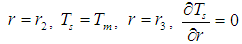
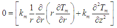
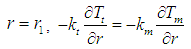
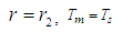
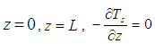
- In the present study, a steady state two dimensional mathematical model for the transport of carbon dioxide through membrane contactor has been developed. The model describes the material and energy transport through the shell and tube side of the gas-liquid hollow fiber membrane contactor utilized in CO2 stripping from potassium glycinate rich solvent. The membrane contactor consists of three segments: tube, membrane, and shell section. In the model, the sweep nitrogen gas flows through the shell side, whereas the rich solvent flows into tube side in a counter-current mode of operation as shown in Fig. 2. The sweep gas is fed to the shell side whereas the rich solvent is fed into the tube lumen side in counter current mode. Carbon dioxide is removed from potassium glycinate rich solvent by diffusing through the membrane pores to shell side where it is swept via nitrogen gas flowing in the shell side.
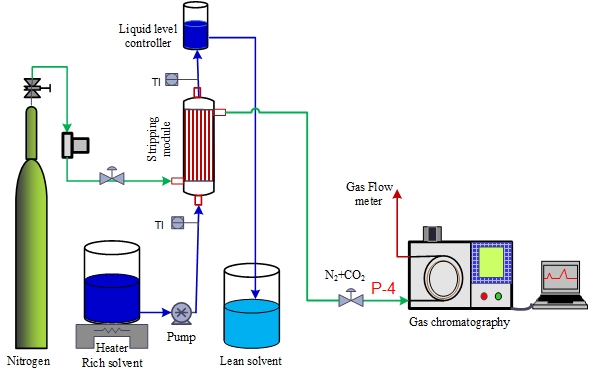 | Figure 1. Demonstration drawing for stripping experiment via hollow fiber membrane |
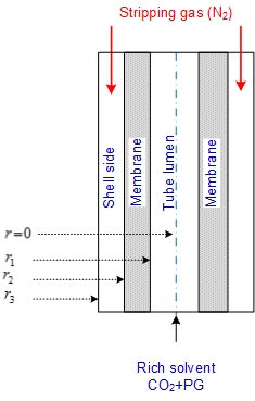 | Figure 2. Illustration diagram for stripping of CO2 in gas–liquid membrane contactor |
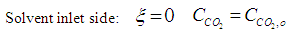
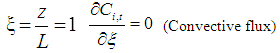
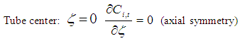
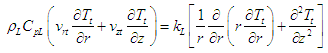
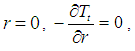
3.1. Tube Side 
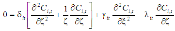
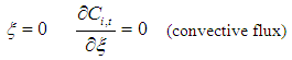
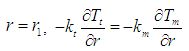
- In the lumen side of the hollow fiber membrane tubes, the basic steady state equations are as follows
 :
: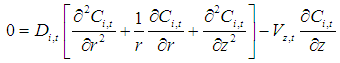 | (1) |
 | (2) |
 The liquid flow within the hollow fibers is laminar:
 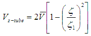 | (3) |
 | (4) |
 | (5) |
 | (6) |
 | (7) |
 :
: | (8) |
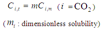
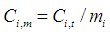
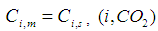
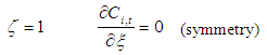
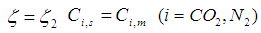
 is the concentrating of component
  in the liquid phase and
  is the concentrating of component
  in the membrane section,
  is the dimensionless solubility of carbon dioxide in solvent.
 3.2. Membrane Section 
- The steady state material balance for the transport of
 inside the membrane, no reaction is taking place in this zone (non-wetting mode).
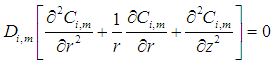 | (9) |
 | (10) |

 | (11) |

 | (12) |
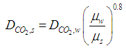
 is the dimensionless constant (mol/mol) and defined using the following equations and is either or
  [6].
[6]. 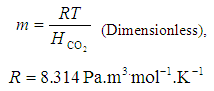 | (13) |
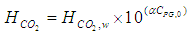 | (14) |
 is the Henry constant for
  in water
 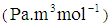 and
and  is a coefficient
  .
.  | (15) |
 | (16) |
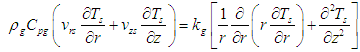
3.3. Shell Side 
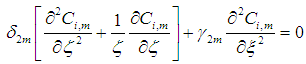
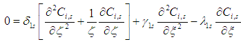
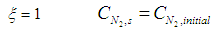
- Nitrogen gas
 is flowing in the shell side:
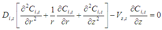 | (17) |
 | (18) |
 | (19) |
 | (20) |
 | (21) |
 | (22) |
 | (23) |
 | (24) |
 | (25) |
 | (26) |
 | (27) |
 | (28) |
 | (29) |
 | (30) |
 | (31) |
 | (32) |
 | (33) |
|
4. Results and Discussion
4.1. Experimental Work
- The constructed membrane module is employed for CO2 stripping from CO2-PG rich aqueous solvent. Figure 3 shows the plot of the experimental results for effect of the velocity of aqueous potassium glycinate solvent on CO2 stripping flux at 25°C. The figure demonstrates a trend of increase in stripping flux with increasing aqueous PG velocity, which is according to Simioni et al. [22] can be ascribed to the decrease in liquid flow boundary layer resistance. The stripping flux showed a maximum of 0.005 (mol/m2.s) at liquid velocity of 0.6 (m/s). By contrast, the effect of gas flow rate on CO2 stripping flux at constant liquid flow rate is insignificant after certain inlet gas flow rate. The figure shows slight increase of stripping flux from 0.0086 to approximately 0.0089 (mol/m2 s) for a gas velocity increase from 0.0045 to 0.1 m/s, no changes in stripping flux was observed with further increase in gas velocity. This is due to the reducing retention time of the gas flowing in the shell and further reduction the amount of CO2 being stripped.Figure 4 is presented here to show the rationale behind selecting stripping of CO2 from PG solution. The figure demonstrates the experimental investigation of the stripping flux for various solvents at different inlet solvents temperatures. It should be noted that the stripping assessment for PG, AMP, DEA and MEA solutions was conducted at the same operating conditions and operating modes. Results show that aqueous potassium glycinate solution, shows the highest stripping flux performance.
4.2. Model Predictions
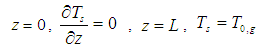
- In this subdivision, the accuracy and performance of the proposed model are shown by simulating the experimental work. The effect of liquid inlet temperature on the CO2 removal are considered under non-wetting condition. Absorption of carbon dioxide with lean potassium glycinate and stripping of CO2 from rich potassium glycinate shows the highest affinity compared with other solvents [28]. Accordingly, PG was selected for model validation. Then, the CFD techniques is used to reveal how the CO2 concentration is distributed across the shell, tube and membrane. The model simulation results a long with experimental data is shown in Fig. 5. As the absorbent temperature has a strong influence on carbon dioxide stripping flux. The effect is investigated against CO2 stripping experimental data. The figure shows the effect of solvent inlet temperature on CO2 stripping flux. The diagram reveals that stripping flux increases with increasing inlet solvent temperature. Model simulation results coincide with experimental finding.The surface plot for the CO2 concentration across membrane module is shown in Fig. 6. CO2 - Rich solvent passes into the lumen side of the membrane, its concentration decrease along the membrane length. The solvent flows in the lumen side of the membrane at temperatures higher than sweeping gas, accordingly temperature varies across the membrane module is a function of the temperature gradient between inlet liquid temperature and inlet gas phase temperature. The gas enters the shell side of the module at 25°C and liquid solvent enters counter currently the lumen side of the membrane at 80°C. The surface plot of this case is depicted in Fig. 7. Research surface method is also performed to support the importance of selecting the high impact of solvent feed temperature on stripping process.
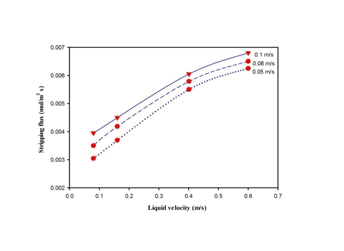 | Figure 3. Effect of solvent liquid velocity on CO2 removal flux at 25 oC, at different gas velocity |
 | Figure 4. Effect of inlet liquid solvent temperature on CO2 removal flux, liquid velocity 0.16 m/s, gas velocity 0.048 m/s |
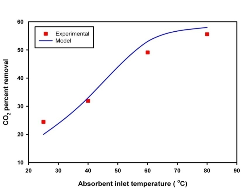 | Figure 5. Comparison of model simulation results and experimental data |
4.3. Design of Experiments; Response Surface Method
- To determine the interference effects between variables, a central composite design was intended which is shown in Table 2. Input variables of the experimental designs, including solvent feed temperature, solvent inlet velocity and stripping gas inlet velocity. Parameters in this work were investigated in three non-coded levels. The following equation correlates these parameters were generated:
 Where F is the carbon dioxide removal flux [mol/m2 s] The Interferential coefficients of which values are determined by the data analysis, L [ml/min] represents the liquid feed rate, G [ml/min] gas feed rate, and T [°C] represents rich solvent temperature. This equation shows how the amount of removing carbon dioxide from rich PG solvent is affected by the mentioned parameters. The model was run for each case and the results obtained from the linear, power and Interferential variables are given in Table 2. The high R value (99.61) also indicates the good fit of the data. The effect of gas flow rate of CO2 stripping flux is minor as shown from the table 2.
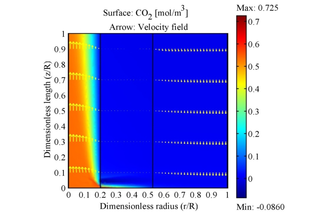 | Figure 6. Surface plot for CO2 concentration across the membrane contactor temperature 25 oC, liquid velocity 0.16 m/s, gas velocity 0.048 m/s |
 | Figure 7. Surface plot of temperature across the membrane contactor temperature, liquid velocity 0.16 m/s, gas velocity 0.048 m/s |
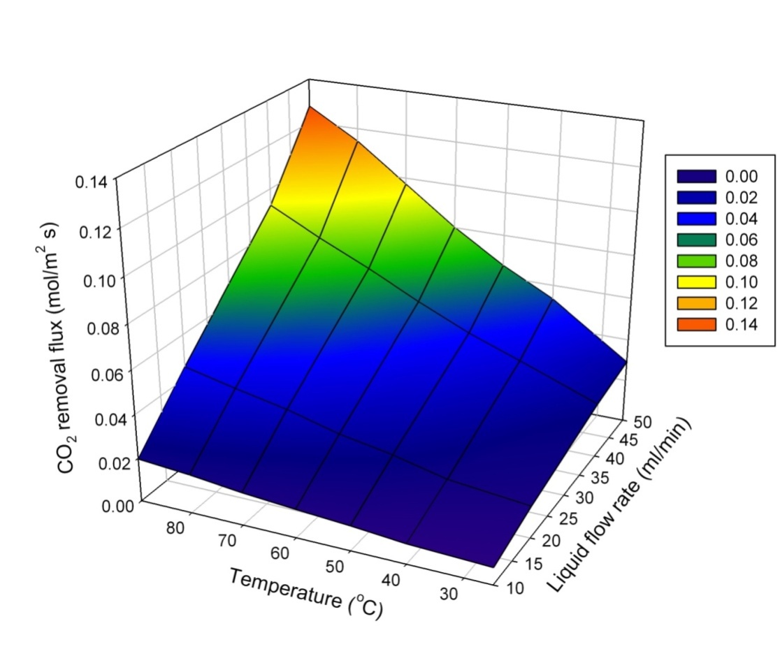 | Figure 8. Effect of operating parameters on membrane stripping performance |
|

5. Conclusions
- In this study, the modeling of CO2 stripping from rich potassium glycinate aqueous solutions been used in absorption of CO2 from natural gas in a hollow fiber membrane contactor was studied. The CFD technique was used to visualize the effects of operating parameters on the distribution of CO2 concentration in the contactor. The effect of stripping gas flow rate, rich solvent temperature and liquid flow rate on CO2 stripping in gas-liquid hollow fiber membrane contactor was investigated both experimentally and theoretically. The experimental findings indicate that liquid phase velocity and liquid temperature has strong impact on stripping flux. The mathematical model was developed to predict the performance of CO2 stripping from CO2 loaded aqueous solvents. The model takes into account material and energy transport equations. The model simulation results match with experimental data and hence the developed model can be used to accurately predict the CO2 removal performance in the polymeric hollow fiber membranes.
Nomenclatures
 Membrane surface area, m2
 Inlet gas concentration, mol m-3
  Effluent gas concentration, mol m-3
 Component concentration, 1: CO2, 2: N2, 3: PG
 Concentration of component
  in the membrane section, mol m-3
 Concentration of component
  in the shell section, mol m-3
 Concentration of component
  in the tube section, mol m-3
 Inlet liquid concentration, mol m-3
 Exit liquid concentration, mol m-3
  Diffusion of component
  ; 1:CO2, 2: N2, 3: PG
  Pore diameter, m
 Inner diameter of hollow fiber diameter, m
 Outer diameter of hollow fiber diameter, m
 Henry’s constant
  Length of hollow fiber membrane, m
 Molecular weight of gas, g mol-1
 Distribution factor
 Pressure, Pa
  Inlet gas flow rate, m3s-1
 Inlet liquid flow rate, m3s-1
 Universal gas constant, 8.314 J mol-1.K-1
 Inner tube radius, m
 Outer tube radius, m
 Inner shell radius, m
 Absolute temperature, K
 Viscosity of gas, Pa s
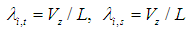
 Velocity of fluid inside the module in z-direction, m s-1
 Average velocity, m s-1
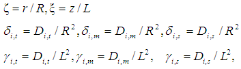
 Axial distance, m Greek letters
 Polymer density, g cm-3
 Membrane surface porosity
 Membrane porosity
 Dimensions module length,
 Dimensionless module radius,