Zhongzheng You
Shanghai University of Engineering Science, Shanghai, 201620, China
Correspondence to: Zhongzheng You, Shanghai University of Engineering Science, Shanghai, 201620, China.
| Email: |  |
Copyright © 2012 Scientific & Academic Publishing. All Rights Reserved.
Abstract
This thesis mainly studies the mathematical model of the variable cycle engine and its optimization. The variable cycle engine working process is very complicated. The working process of it is not only a single component of thermal processes, but contains all the components and their interaction as awhole. All the components are interrelated and interact with each other. The variable cycle engine is divided into general structure, each structure is typical, independence, versatility and connectivity, then the mathematical model of the parts is established. Finally simulation with MATLAB software to solve the seven balance equation of the variable cycle engine model under known the condition of external input, and the model is evaluated.
Keywords:
Variable cycle engine, Modularmodeling, Balance equation
Cite this paper: Zhongzheng You, Component-level Modeling Technology and Optimization for Variable Cycle Engine, American Journal of Mathematics and Statistics, Vol. 3 No. 6, 2013, pp. 428-435. doi: 10.5923/j.ajms.20130306.18.
1. Introduction
The variable cycle engine can work in the big thrust with high speed and lower fuel consumption with low speed at the same time. The variable cycle engine has drawn the attention of the various aviation powers in many countries because of these advantages, and it is one of the important research directions of aircraft engines.
2. The Structure and Basic Principle of Variable Cycle Engine
2.1. The Basic Structure
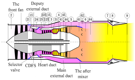
The basic structure of the double duct variable cycle engine, as shown in figure 1, figure 2, The main components are: Inlet, Fan, Deputy external duct (DED), CDFS duct, CDFS, Main external duct (MED), The former mixer (TFM), High pressure compressor (HPC), Main chamber (MC), High pressure turbine (HPT), Low pressure turbine (LPT), The after mixer (TAM), afterburners, exhaust nozzle. The digital serial Numbers in the figure mean engine section parameters.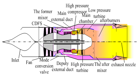 | Figure 1. The basic construction of variable cycle engine |
 | Figure 2. The structure diagram of double duct variable cycle engine |
2.2. The Working Principle
The connection between the engine parts as shown in figure 3, Variable cycle engine is a dual rotor motor, The fan is connected to the low pressure turbine, CDFS and High pressure compressor also be connected tothe high pressure turbine, As shown in figure 3.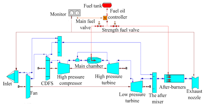 | Figure 3. The diagram of a variable cycleengine working principle |
There are two kinds of working mode about the variable cycle engine, turbojet and turbofan, as in[1]. When engine working in subsonic cruise low power state, the mode conversion valve open, make more air into the deputy external duct, at the same time the former mixer is wide opened. Open the after mixer, increasing the bypass ratio; reduce fuel consumption, the engine working at the model of turbofan this time. When engine working in the state of supersonic cruise, acceleration and climbing, the former mixer is smaller, selector valve closed, most of the gas forced into the core engine, produce high thrust, the engine working at the model of turbojet this time.
3. Component Modeling Method of Variable Cycle Engine
The characteristics of the variable cycle engine can be achieved by experiment method and the calculation method. But the experiment method needs to develop sophisticated equipment, invest a huge sum of money and huge energy consumption. Because of this, the experiment method is often adopted.With the continuous improvement of computing power and the deepening of the research engine mathematical model, computer simulation accuracy has been improved to some extent make up for the deficiency of the experimental method. The variable cycle engine is composed of inlet, compressor, combustion chamber and turbine, nozzles and other components. With the computer simulation of these components, we can get the simulation of the engine.
3.1. The Modular Model
From the figure of the principle of variable cycle engine, we know that the working process of the variable cycle engine is very complex, and the characteristics of the components have a very close relationship with the characteristics of the engine. So we must study the characteristics of components before we study the properties of the engine and then establish its mathematical model. And build a mathematical model of the whole system basis on the mutual restriction relations between various components.Decomposability of the system is the base of modularized modeling. That means the system can be decomposed into several subsystems. For each subsystem we built a model. Dividing according to the actual physical system module, make a module has the relative independence of physical, namely to complete a separate physical function, at the same time ensure that each module has the independence of the math. That means all of the equations describing the physical component characteristics and calculation are included in the module within the program. This makes the modeling and simulation process becomes natural, intuitive, and the gap between the physical model and computational model narrow. At the same time can make sub models for repeated use, greatly shorten the time of the modeling and simulation. So, according to the actual physical device to separate modules, has become the principle of modular modeling of module partition.To the system we study should make reasonable modular decomposition and the module have the following features:1. The module is the base of the basic unit of the system model, it can no longer small, and the system dynamic model program is composed of the basic module subroutine.2. Modulepartition is based on completely independent of the physical device and the component. They have clear physical boundaries and enough physical independence.3. Module with high mathematics independence. It stipulates that all of thee equations describing the part feature are contained inside the module, theoutput of the module accord to the module itself, energy, mass and momentum to calculate fluid properties, on the side of the change and not as a function of the other variables in a module to calculate. It can be used as a basic unit to attend to a larger system, and can also be used separately which do not add any other simulation module to determine the physical device.4. The module has good compatibility;it is the key to the modular modelling, as in[2]. The difficulty of modular modelling is interactive and the coupling within the system. In the model system of modularization, the module design goal is to reduce the coupling between modules, increase module cohesion. In order to achieve the design goal, we need to make sure that physics and mathematics independence of the module.The flow diagram that adopting modular decomposed about variable cycle engine shown in figure 4.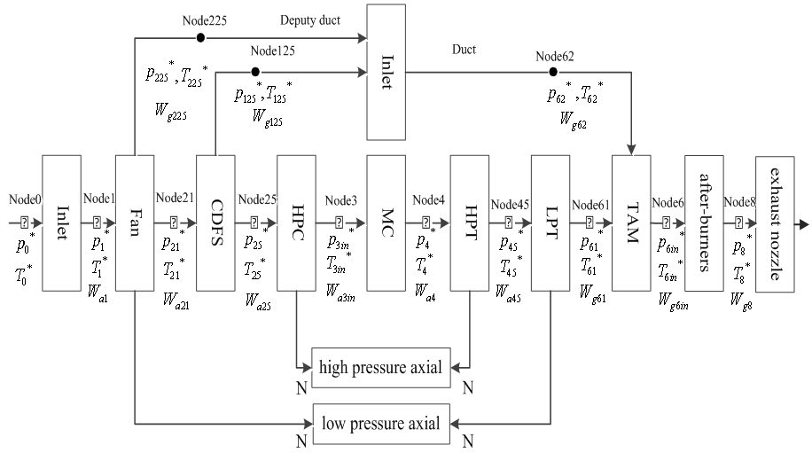 | Figure 4. The flow diagram of the engine |
3.2. The Relevant Data in the Model
The input parameter of an engine mathematical model is the flying height ( ), Mach number (
 ), the main fuel flow (
 ), the strength of fuel flow (
 ) and the nozzle area (
 ). Under the condition of guarantee engine work output parameters are the motor rotor speed, the cross section of aerodynamic parameters and performance. According to the modular modeling, describe the working process of the engine component level model mainly includes the following three aspects:1. According to the aerothermodynamics properties and component properties of the engine establish mathematical model, as in[3].2. According to the engine internal flow channel, traffic, power balance and rotor dynamic principle to build models which reflect the working process of engine stability, dynamic mathematic, and it means some equations to describe a series of interactions about the components work together.3. Using a numerical method to solve the work equations to identify the common working point and get the engine performance parameters.When we get some of the results about above, we can build engine module corresponding database, and it can be used in the back of the calculation.
3.3. Engine Numerical Simulations and the Solution of the Common Working Point
When the engine working on parts matching, it's conditioned by the following seven balance equation, as in[4]:Power balance equation of low voltage axial: | (1) |
 is the fan consumed power,
  is the low pressureturbine power,
  is the intermediate shaft mechanical efficiency.Power balance equation of highpressure axial:
 | (2) |
 and
and  are the power which the highpressure compressor and CDFS consumed,
  is the power of the high pressure turbine,
  is the mechanical efficiency of the high-speed shaft.The balance equation of high pressure turbine inlet flow:
 | (3) |
 is the high pressure turbine inlet section gas flow,
  is the high pressure turbine flow which gets from the high pressure turbine of characteristic data about high pressure turbine.The balance equation of low pressure turbine inlet flow:
  | (4) |
 is the high pressure turbine inlet section gas flow,
  is the high pressure turbine flow which gets from the high pressure turbine of characteristic data about high pressure turbine.The static balance equation of the after mixer:
 | (5) |
 and
and  are static pressure of within mixer and external duct, they should be balanced.The balance equation of exhaust area:
  | (6) |
 is the area of the given variable nozzle 8, and
  .
.  is the area of nozzle 8 which calculate from the formula.The balance equation of fan outlet flow:
 | (7) |
 is the flow of fan outlet,
  is the flow of Deputy external ductand
  is the inlet flow of CDFS.
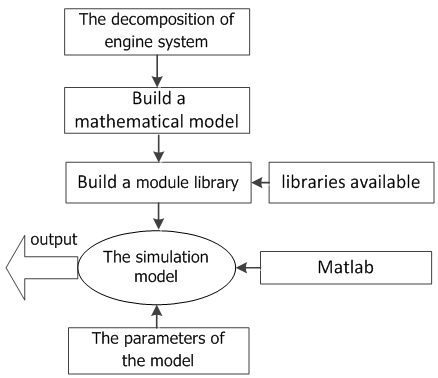 | Figure 5. The flow chart of building engine system model |
Each node in the flow diagram of engine can be obtained which contain the total temperature, total pressure and flow rate when we know the input data, as in[5]:  ,
, ,
,  ,
,  ,
,  ,
,  ,
,  .When engine working in steady–state, it means
  , Working equations and the characteristics of components reflects the engine internal aerodynamic and thermodynamic property together, is the description of the engine internal complex pneumatic thermal abstract mathematical process, and also has a clear physical meaning. In order to obtain the thermal parameters of the engine through the mathematics description, the problem is converted into working out the equations of components working together as a system which is the essence of engine component level model modelling.Therefore, to determine the cooperating points of engine problems are summed up insolving the equations. But the nonlinear equations have no obvious mathematical expression, so we can't get the analytic solution. We use numerical methods to solve the nonlinear mathematical model of the engine. In the first, initial values of independent variables are given:
  ,
, ,…, substituting the values in the engine model, then parameters are calculated along the engine process, after that Check whether equations satisfy common working conditions and the control scheme be selected. If they satisfied, working point of each part under the initial values is the common working point of the engine. Instead we get a set of residual equation.We use the vector represents some initial values:
 | (8) |
We use the vectorrepresents some parameter: | (9) |
Obviously, the vector  is a function of initial values, namely:
 | (10) |
This non-linear equation can't be expressed explicitly, but only can be calculated according to the relationship ofthe engine thermodynamic model to get the relationship between the residual  and initial value vector
  .Solving equations:
 | (11) |
We use the Newton-Raphsonmethod to solve the nonlinear equations. Take seven parameters: the speed of high pressure  , pressure ratio of fan
  , pressure ratio of CDFS
  , pressure ratio of high pressure compressor
  , the outlet temperature of main combustion chamber
  , pressure ratio of high pressure turbine
  , pressure ratio of low pressure turbine
  .The nonlinear equations:
 So:
So: | (12) |
Assume that the initial value are: Iterative calculation to step K:
 The partial differential equations for nearby the nonlinear equations
  :
: | (13) |
Using the difference quotient instead of derivative: Also like this:
 | (14) |
:  order coefficient matrix
 : The solution vector.So we get the values of
  and the values of the variables:
 | (15) |
We repeated iteration like this, continuously revised the initial value, until the error can be satisfied by the requirements of the accuracy of the balance equation. And the numerical solution was obtained through the corresponding procedure with MATLAB which is the cooperating point of the engine, as in [6].The initial values are: ,
, ,
, ,
,  ,
, ,
, ,
, Running simulation program we get results and graphics as follows:
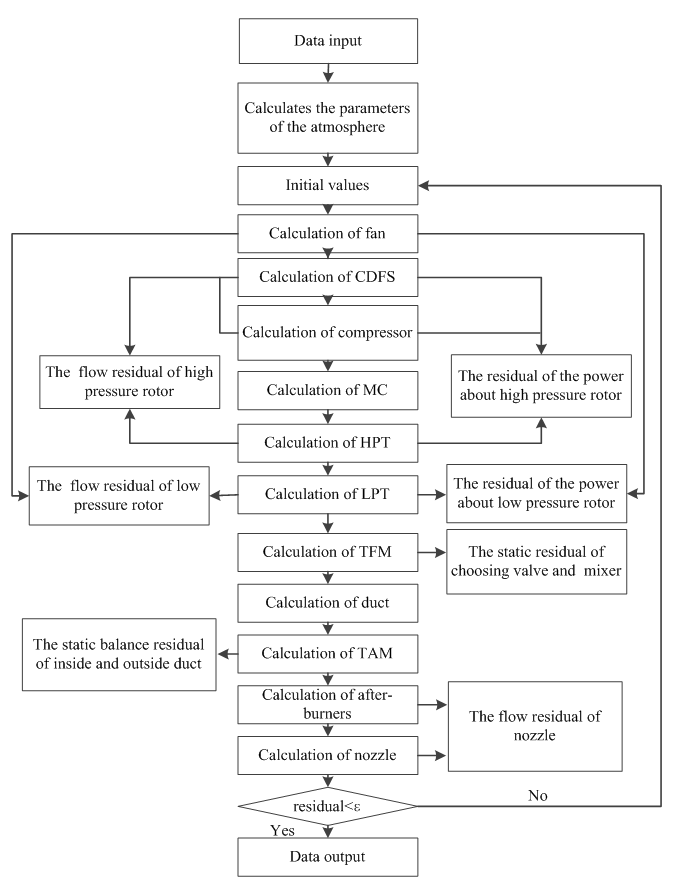 | Figure 6. The diagram about simulation of engine |
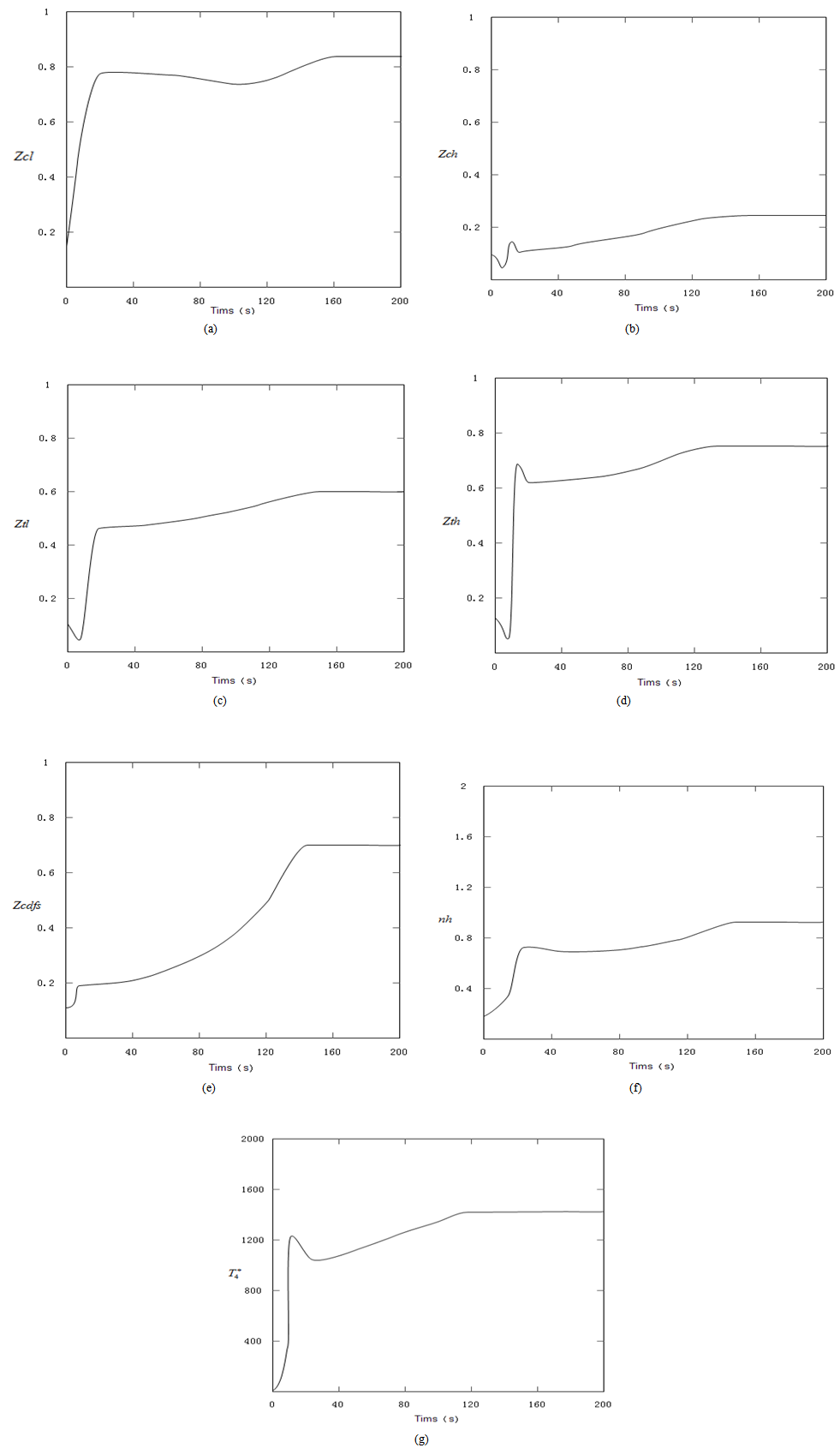 | Figure 7. The results of equations after steady state iteration |
As you can be seen in the above figures, the system achieved a stable state after about 160 times of iteration. Even in the initial state deviation from steady state point, the system can quickly return to the steady state.The steadystate value are: ,
, ,
, ,
,  ,
, ,
, ,
, (Note: when residual of equations
  reached convergence)These are the solutions of seven nonlinear equations.
4. Evaluation of the Model
Variable cycle engine is a very complex power plant, involving fluid mechanics, structural mechanics, heat transfer, combustion control and many other subjects, as in[7]. Mathematical modelling plays an important role in this research. Modelling is a very important in the simulation experiment, advanced modelling method is the important support of advanced technology. Modular modelling is a kind of advanced modelling method has been gradually applied in the simulation field which has high value in practical application. The work in this paper is just at the beginning stage, and it has not done the microscopic arrangement job, and the model can be improved from several respects: 1. Considering more about the physical characteristics of the components, reducing the degree of model simplification to improve the simulation accuracy.2. Making the model library perfect and in detail, such as establishing the model of a centrifugal compressor, the model of cooling chamber and the model of export adjustable tail nozzle.
References
| [1] | GOU Xue-zhong, ZHOU Wen-Xiang, HUANG Jin-quan, Component-level modeling technology for variable cycle engine, Journal of Aerospace Power, 2013, 28(1): 104-111. |
| [2] | LIU Hong-bo, WANG Rong-qiao, Investigation of General Structure andMode TransitionMechanism of Variable Cycle Engine, Aeroengine, 2008, 34: 1-5. |
| [3] | LIU Zeng-wen, WANG Zhan-xue, HUANG Hong-chao, CAI Yuan-hu, Numerical simulation onperformance of variable cycle engines, Journal of Aerospace Power, 2010, 25(6): 1310-1315. |
| [4] | FANG Chang-de, Variable Cycle Engines, Gas Turbine Experiment and Research, 2004, 17(3): 1-5. |
| [5] | WANG Yuan, LI Qiu-hong, HUANG Xiang-hua, Research of variable cycle engine modeling technique, Journal of Aerospace Power, 2013, 28(4): 954-960. |
| [6] | ZHANG Rong, YE Zhi-feng, XUE Yi-chun, Simulation Research on Adjustment Plan to Mode Transition of Variable Cycle Engine, Measurement & Control Technology, 2011, 30: 47-50. |
| [7] | XI Wang, “MODULAR MODELING AND SYSTEM- LEVER SIMULAIONON AEROENGINE,” Doctor Degree thesis. Shanghai, China, Shanghai Jiao Tong University. 2004.1. |


 ), Mach number (
 ), the main fuel flow (
 ), the strength of fuel flow (
 ) and the nozzle area (
 ). Under the condition of guarantee engine work output parameters are the motor rotor speed, the cross section of aerodynamic parameters and performance. According to the modular modeling, describe the working process of the engine component level model mainly includes the following three aspects:1. According to the aerothermodynamics properties and component properties of the engine establish mathematical model, as in[3].2. According to the engine internal flow channel, traffic, power balance and rotor dynamic principle to build models which reflect the working process of engine stability, dynamic mathematic, and it means some equations to describe a series of interactions about the components work together.3. Using a numerical method to solve the work equations to identify the common working point and get the engine performance parameters.When we get some of the results about above, we can build engine module corresponding database, and it can be used in the back of the calculation.
 is the fan consumed power,
  is the low pressureturbine power,
  is the intermediate shaft mechanical efficiency.Power balance equation of highpressure axial:
 and
and  are the power which the highpressure compressor and CDFS consumed,
  is the power of the high pressure turbine,
  is the mechanical efficiency of the high-speed shaft.The balance equation of high pressure turbine inlet flow:
 is the high pressure turbine inlet section gas flow,
  is the high pressure turbine flow which gets from the high pressure turbine of characteristic data about high pressure turbine.The balance equation of low pressure turbine inlet flow:
 is the high pressure turbine inlet section gas flow,
  is the high pressure turbine flow which gets from the high pressure turbine of characteristic data about high pressure turbine.The static balance equation of the after mixer:
 and
and  are static pressure of within mixer and external duct, they should be balanced.The balance equation of exhaust area:
 is the area of the given variable nozzle 8, and
  .
.  is the area of nozzle 8 which calculate from the formula.The balance equation of fan outlet flow:
 is the flow of fan outlet,
  is the flow of Deputy external ductand
  is the inlet flow of CDFS.
 ,
, ,
,  ,
,  ,
,  ,
,  ,
,  .When engine working in steady–state, it means
  , Working equations and the characteristics of components reflects the engine internal aerodynamic and thermodynamic property together, is the description of the engine internal complex pneumatic thermal abstract mathematical process, and also has a clear physical meaning. In order to obtain the thermal parameters of the engine through the mathematics description, the problem is converted into working out the equations of components working together as a system which is the essence of engine component level model modelling.Therefore, to determine the cooperating points of engine problems are summed up insolving the equations. But the nonlinear equations have no obvious mathematical expression, so we can't get the analytic solution. We use numerical methods to solve the nonlinear mathematical model of the engine. In the first, initial values of independent variables are given:
  ,
, ,…, substituting the values in the engine model, then parameters are calculated along the engine process, after that Check whether equations satisfy common working conditions and the control scheme be selected. If they satisfied, working point of each part under the initial values is the common working point of the engine. Instead we get a set of residual equation.We use the vector represents some initial values:

 is a function of initial values, namely:
 and initial value vector
  .Solving equations:
 , pressure ratio of fan
  , pressure ratio of CDFS
  , pressure ratio of high pressure compressor
  , the outlet temperature of main combustion chamber
  , pressure ratio of high pressure turbine
  , pressure ratio of low pressure turbine
  .The nonlinear equations:
 So:
So:
 Iterative calculation to step K:
 The partial differential equations for nearby the nonlinear equations
  :
:
 Also like this:
 order coefficient matrix
 : The solution vector.So we get the values of
  and the values of the variables:
 ,
, ,
, ,
,  ,
, ,
, ,
, Running simulation program we get results and graphics as follows:

 ,
, ,
, ,
,  ,
, ,
, ,
, (Note: when residual of equations
  reached convergence)These are the solutions of seven nonlinear equations.
 Abstract
 Reference
 Full-Text PDF
 Full-text HTML