-
Paper Information
- Next Paper
- Previous Paper
- Paper Submission
-
Journal Information
- About This Journal
- Editorial Board
- Current Issue
- Archive
- Author Guidelines
- Contact Us
American Journal of Medicine and Medical Sciences
p-ISSN: 2165-901X e-ISSN: 2165-9036
2025; 15(12): 4283-4288
doi:10.5923/j.ajmms.20251512.18
Received: Nov. 3, 2025; Accepted: Nov. 28, 2025; Published: Dec. 8, 2025

Innovative Device for Surgical Treatment of Acetabular Injuries
 Abstract
 Reference
 Full-Text PDF
 Full-text HTML
Mirzaev Sh. H.1, Gaipov Z. A.2, Dursunov A. M.3
1PhD, Head of the Department of Traumas` Consequences of the Republican Specialized Scientific-Practical Medical Center of Traumatology and Orthopedics., Tashkent, Uzbekistan
2Doctor of the Department of Traumas` Consequences of the Republican Specialized Scientific-Practical Medical Center of Traumatology and Orthopedics, Tashkent, Uzbekistan
3DSI, Senior Researcher, Department of Traumas` Consequences of the Republican Specialized Scientific-Practical Medical Center of Traumatology and Orthopedics, Tashkent, Uzbekistan
Correspondence to: Gaipov Z. A., Doctor of the Department of Traumas` Consequences of the Republican Specialized Scientific-Practical Medical Center of Traumatology and Orthopedics, Tashkent, Uzbekistan.
| Email: |  |
Copyright © 2025 The Author(s). Published by Scientific & Academic Publishing.
This work is licensed under the Creative Commons Attribution International License (CC BY).
http://creativecommons.org/licenses/by/4.0/

The study presents the results of experimental research aimed at evaluating the mechanical properties, structural reliability, and functional performance of an innovative device designed for the surgical treatment of acetabular fractures. The device, representing a modified clinic plate with enhanced fixation elements, was tested using a complex biomechanical protocol in the laboratory of structural strength and seismic resistance of the Institute of Mechanics and Seismic Resistance of Structures of the Academy of Sciences of Uzbekistan. A test specimen simulating comminuted acetabular fractures was constructed, incorporating both bone components and the newly developed fixation plate. Two strain-gauge displacement sensors were calibrated and installed to record micro-movements under controlled axial compression. Mechanical loading was performed on a UIM-50 universal testing machine with stepwise increases in compressive force. Experimental analysis demonstrated that the device ensures stable elastic behavior under loads up to 33.0 kgf, with the total deformation not exceeding 0.48 mm and without any residual displacement. Further load escalation resulted in the development of plastic deformation in the bone–implant system, indicating the structural limits of the device and defining its operational safety range. A load of 54.0 kgf led to direct tibial contact with the acetabulum and deformation of the implant. The results confirm that the innovative acetabular fixation plate possesses sufficient mechanical strength, adequate rigidity, and reliable stabilization capacity under physiological loads. These findings support its clinical applicability for the management of complex acetabular fractures and justify its introduction into surgical practice.
Keywords: Acetabular fractures, Internal osteosynthesis, Clinical plate, Additive technologies
Cite this paper: Mirzaev Sh. H., Gaipov Z. A., Dursunov A. M., Innovative Device for Surgical Treatment of Acetabular Injuries, American Journal of Medicine and Medical Sciences, Vol. 15 No. 12, 2025, pp. 4283-4288. doi: 10.5923/j.ajmms.20251512.18.
1. Introduction
- Due to the rapid urbanization of society, a steady increase in pelvic and acetabular injuries is observed in the structure of modern trauma. Among the most severe musculoskeletal injuries in the structure of polytrauma are injuries to the pelvic ring and acetabulum, which occur in up to 10% of all trauma patients. Acetabular fractures, accompanied by displacement of fragments and hip dislocation, account for 7-16% of all pelvic fractures, according to some researchers. The demographic structure of this type of injury is dominated by individuals of working age, primarily men, indicating the socioeconomic significance of this problem [1,2,4].A vast number of surgical treatment options for acetabular fractures have been developed, described in the literature, and implemented, but the issue remains unresolved. It has been noted that the disability rate for patients undergoing surgery is almost three times lower than for those treated conservatively [3,5].Due to the variety of acetabular fracture types, data regarding the choice of surgical treatment method are highly controversial. However, timely restoration of hip joint anatomy is essential for the subsequent functional prognosis. Therefore, we prefer surgical correction of fragment displacement to achieve congruence of the articular surfaces. Late complications of acetabular injuries (aseptic necrosis of the femoral head, development of heterotopic ossification, etc.) are generally associated with poor fracture repositioning [6,9,10].Numerous studies have documented the undeniable advantages of open osteosynthesis of the acetabulum, which allows for precise repositioning and rigid fixation of fragments, which positively impacts both immediate and long-term treatment outcomes. Moreover, adequate repositioning and stabilization of fragments is achieved with a surgical approach as close as possible to the fracture site. This minimizes trauma to adjacent soft tissues. Despite the steadily increasing incidence of fractures, internal osteosynthesis for complex acetabular fractures has been implemented in only a few large trauma centers. One of the main problems is the delay in patients' admission to specialized centers for osteosynthesis [7,8].Purpose of the study. Study of mechanical properties of the clinic plate.
2. Materials and Methods
- The closest in technical essence is a fixator for fractures of the acetabulum, containing a curved plate with fastening holes for screws, characterized in that, in order to ensure one-stage restoration of the congruence of the articular surface and strong fixation of fragments, the plate is made in the form of a polygon with curved sides and forms a conical surface (SU, A.s. No. 1671280, A 61 B 17/58, 23.08.91).This device for treating acetabular fractures is designed to provide stable and rigid fixation of bone fragments in comminuted fractures and to ensure congruence of the various sections of the acetabulum. The device comprises a gently curved arcuate plate with mounting holes for screws. Along the edge of the minor arc, the plate has four equally spaced, 90-degree triangular pins with a base size of 1.5 mm and a height of 3 mm for fragment fixation. In the center of the major arc, a 15x25 mm bar is positioned at an angle of 100 to 130 degrees with mounting holes for additional fixation to the pelvic bones. At the ends, ear-shaped bends with a radius of 10 mm, positioned at an angle of 125 to 130 degrees, provide secure fixation to the pelvic bones.The device is easy to use and improves the reliability and stability of fixation in the treatment of acetabular fractures. It is recommended for widespread use in clinical practice.
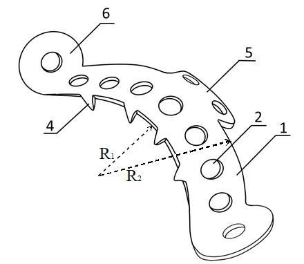 | Figure 1. Schematic representation of the innovative acetabular fixation plate with anatomical curvature, multiple fixation openings, and reinforced structural elements designed to ensure stable congruence of acetabular fragments |
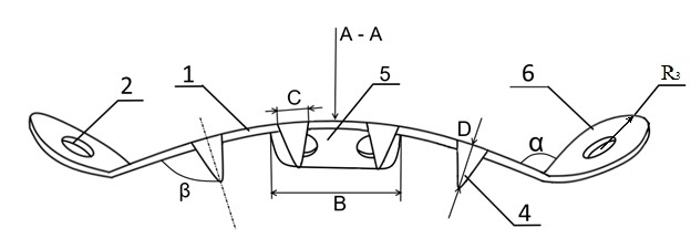 | Figure 2. Illustration of the acetabular fixation device in assembled position showing the placement of screws, angular arrangement of fixation tabs, and the overall configuration of the plate relative to the acetabular surface |
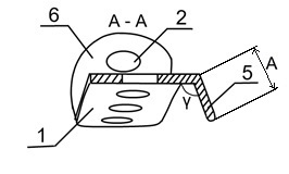 | Figure 3. Cross-section A–A demonstrating the structural profile of the fixation plate, the thickness distribution, the fixation pin geometry, and the interaction of the implant with the acetabular cortical bone |
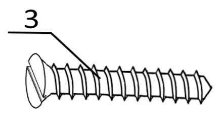 | Figure 4. Design of the bone fixation screw used with the acetabular plate, showing thread geometry, core diameter, and head configuration intended for secure osteosynthesis |
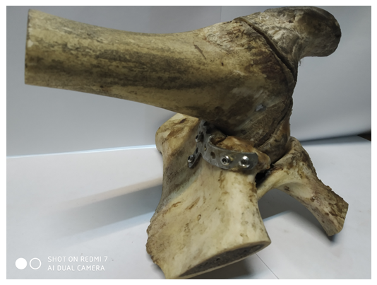 | Figure 5. Test sample |
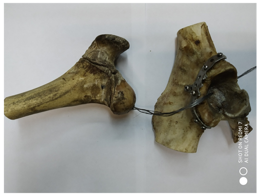 | Figure 6. Parts of the test specimen |
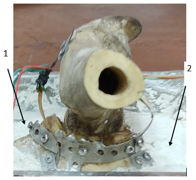 | Figure 7. The test sample with a smoothly curved arc-shaped plate and with installed displacement sensors 1 and 2 |
3. Results and Discussion
- Measuring any sample parameter requires the use of measuring transducers. The reliability of the obtained results depends on how optimally the parameters of the measuring transducers are selected and the extent to which their characteristics meet the experimental objectives. A crucial step in preparing for experiments is the calibration of the measuring channels, taking into account the influence of all the measuring systems involved in the process.For the production of strain gauge displacement transducers, thin elastic steel plate-type springs of varying base lengths and widths are prepared. The dimensions of each strain gauge displacement transducer are individually selected, taking into account the characteristics of the parameters being recorded and their installation location. One of the key requirements for installing the transducers on the test object is that they must operate under elastic loads within the measured range, without imparting additional force to the system. These specially prepared strain gauge displacement transducers, consisting of an elastic flexible steel plate, have a thickness of δ = 0.08 mm and a plate width of a ≤ 10.0 mm.Strain gauges with varying base lengths and resistances are used in the manufacture of displacement sensors. Depending on the strain gauge's base length and design, the range of measured values can be expanded to suit the experimental setup. 2FKPA-30-200 HV strain gauges with a 30 mm base and 200 ohm resistance were used in the manufacture of displacement sensors (Fig. 8).
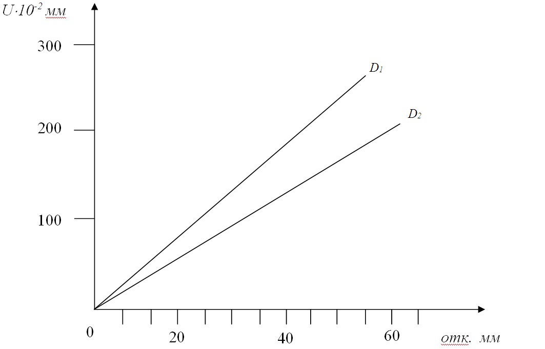 | Figure 8. Calibration graphs of displacement sensors: D1 – sensor No. 1; D2 – sensor No. 2 |
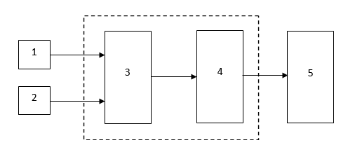 | Figure 9. Electronic block diagram of the measuring complex |
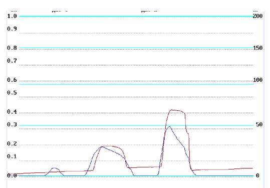 | Figure 10. Changes in the displacement of the tibia head relative to the acetabulum |
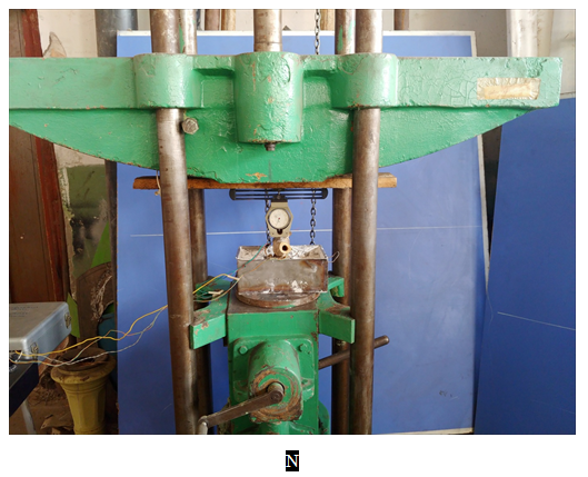 | Figure 11. General view of the installation of the universal testing machine UIM-50 |
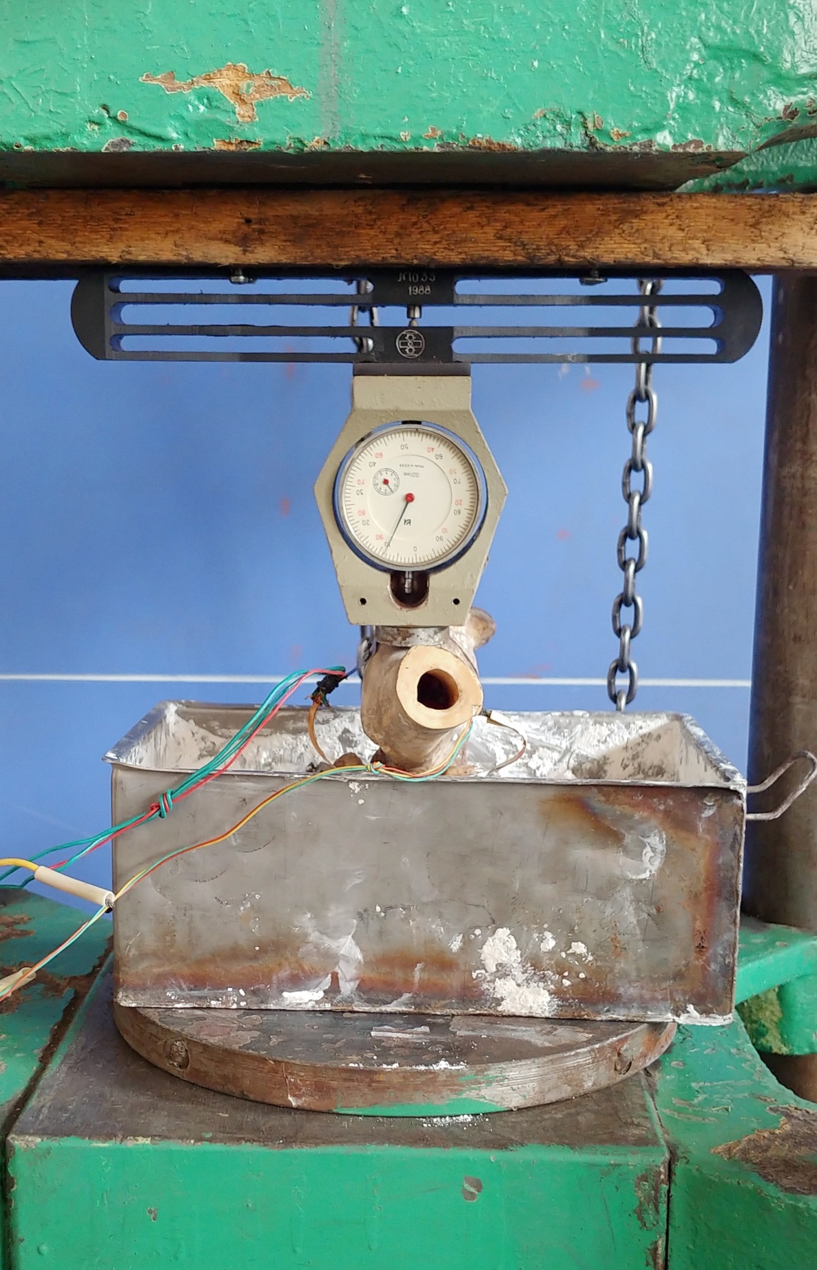 | Figure 12. The test object with the dynamometer DOSM-0.2-10 |
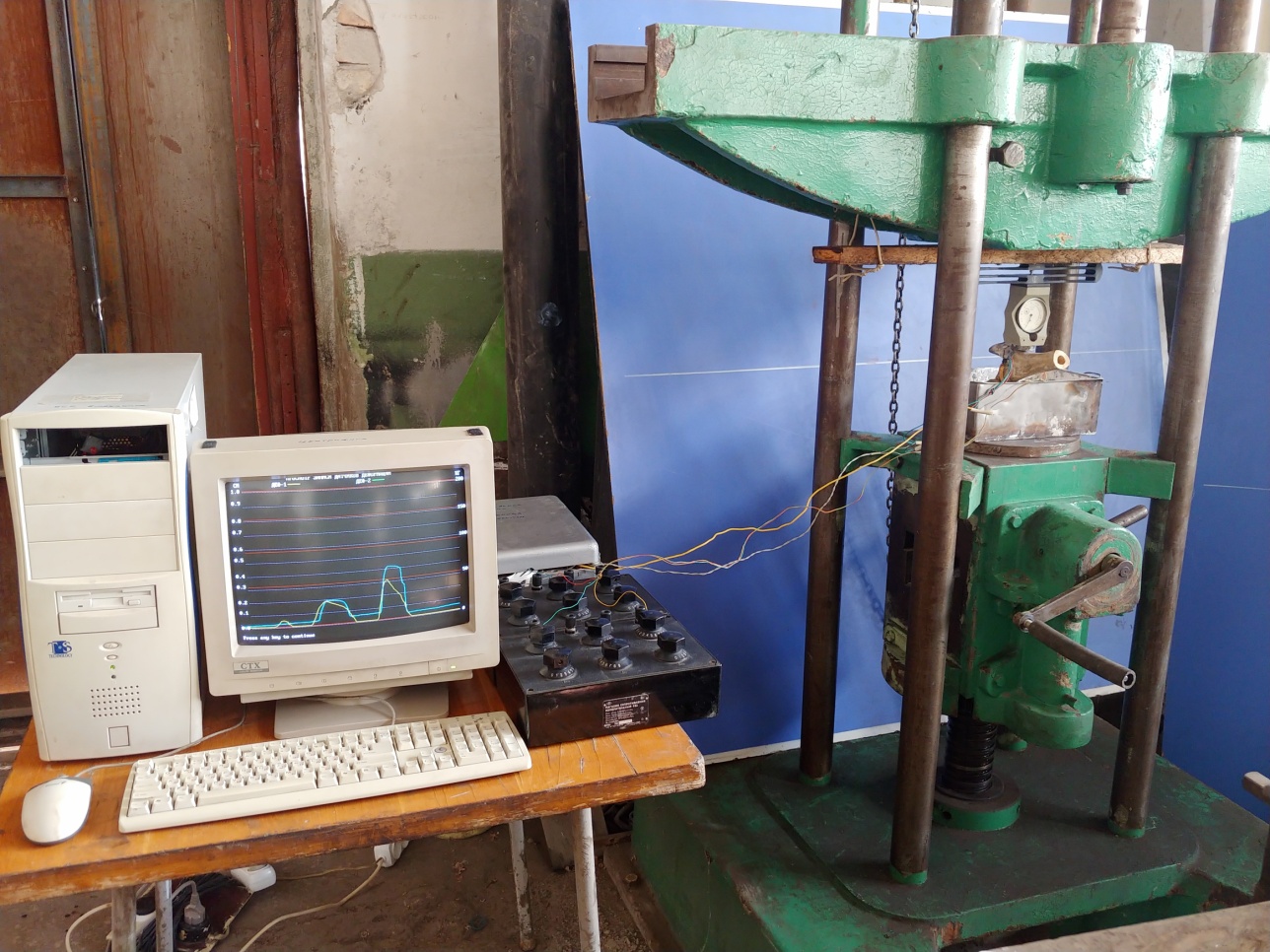 | Figure 13. General view of the electrical measuring complex |
 | Figure 14. Graph of change in relative displacement depending on compressive load |
4. Conclusions
- 1. A method has been developed for measuring relative micro-displacements at the installation site of a device for treating acetabular fractures under the action of compressive loads of varying intensity.2. The maximum numerical values of the load at which the plate operates in elastic mode were determined to be P = 33.0 kgf. The maximum total deformation is Umm = 0.48 mm, and there is no residual deformation. Further increases in load lead to residual deformation, the value of which increases with increasing applied load.3. The material used for the device ensures the necessary strength during use.