-
Paper Information
- Next Paper
- Previous Paper
- Paper Submission
-
Journal Information
- About This Journal
- Editorial Board
- Current Issue
- Archive
- Author Guidelines
- Contact Us
American Journal of Intelligent Systems
p-ISSN: 2165-8978 e-ISSN: 2165-8994
2017; 7(3): 73-76
doi:10.5923/j.ajis.20170703.07

Smart Cane for the Visually Impaired
 Abstract
 Reference
 Full-Text PDF
 Full-text HTML
Muriel Pinto, Rose Denzil Stanley, Sheetal Malagi, Veena Parvathi K., Ajithanjaya Kumar M. K.
Department of Electrical and Electronics, St Joseph Engineering College, Mangalore, India
Correspondence to: Muriel Pinto, Department of Electrical and Electronics, St Joseph Engineering College, Mangalore, India.
| Email: |  |
Copyright © 2017 Scientific & Academic Publishing. All Rights Reserved.
This work is licensed under the Creative Commons Attribution International License (CC BY).
http://creativecommons.org/licenses/by/4.0/

Currently, visually impaired people use a traditional cane as a tool for directing them when they move from one place to another. Although, the traditional cane is the most widespread means that is used today by the visually impaired people, it could not help them to detect dangers from all levels of obstacles. In this context, we propose a new intelligent system for guiding individuals who are visually impaired or partially sighted. The system is used to enable visually impaired people to move with the same ease and confidence as a sighted people. Also the system helps in detecting the potholes. The system is linked with a GSM-GPS module to pin-point the location of the visually impaired person and to establish a two way communication path in a wireless fashion. Moreover, it provides the direction information as well as information to avoid obstacles based on ultrasonic sensors. A buzzer and vibrator motor are also added to the system. The whole system is designed to be small, light and is used in conjunction with the white cane. The results have shown that the blinds that used this system could move independently and safely.
Keywords: Smart cane, Visually impaired, Ultrasonic sensor, GPS-GSM module
Cite this paper: Muriel Pinto, Rose Denzil Stanley, Sheetal Malagi, Veena Parvathi K., Ajithanjaya Kumar M. K., Smart Cane for the Visually Impaired, American Journal of Intelligent Systems, Vol. 7 No. 3, 2017, pp. 73-76. doi: 10.5923/j.ajis.20170703.07.
Article Outline
1. Introduction
- Globally, the number of people of all ages living with sight loss is estimated to be 285 million, of who 39 million are visually impaired according to the World Health Organization (WHO). Among many constraints faced by a visually impaired person, the challenge of independent navigation and mobility is prominent. Generally visually impaired people rely on assistance of sighted persons to find their way or need an accompanying person to follow; at least during a training period. This means that the majority of visually impaired people cannot find their way autonomously in an unknown area. Generally visionless persons use a white cane or walking cane.Electronic oriented technology like Ultrasonic sensor can be used to assist the visually impaired person. In this technology, energy waves are emitted ahead, then it is reflected from obstacles in the path of the user and detected by a matching sensor. Thus, the distance to the obstacle is calculated according to the time variance between the two signals. We have used different vibration intensities to indicate the distance of the object using the vibration motor. If the visually impaired person is too close to the obstacle the motor will vibrate at a higher intensity and also a buzzer will be turned on, alerting the visually impaired man to walk in different direction. In addition to this the smart cane will be linked with the smart phone, so that he can make use of maps. GPS system is used by visually impaired persons to determine and verify the correct route and also if the person fell on the ground the GSM-GPS module receives the information from the GPS satellite and transfers the latitude and longitude information as SMS message to a predefined mobile number.
2. Characteristics of the Visually Impaired
- A person who has been clinically determined to have a visual acuity of 20/70 or less in the stronger eye is diagnosed as visually impaired, while a person who is legally visually impaired is defined to have a visual acuity of 20/200 or less in the stronger eye. People whose visual acuity is at either of these levels receive governmental benefits, such as the right to possess a white cane or own a guide dog. A white cane is often carried by the visually impaired to give more freedom to the individual. The two main functions of the cane are identification and safety; it should alert the user to obstructions and changes in their path and also notify the seeing pedestrians and drivers that the user has some degree of vision loss. There are three types of white canes: identification canes, support canes, and long canes, Support canes have the same purpose as identification canes, except that they provide more support and balance for the legs and body of the user. Long canes, the type of cane chosen to be modified into a Smart Cane, reach the user’s sternum and provide the most safety for the user, alerting them of terrain and height changes, walls, doors, and obstacles. They are also the most visible to others.
3. Smart Cane
- All paragraphs must be indented. All paragraphs must be justified alignment. With justified alignment, both sides of the paragraph are straight.
4. Design of the System
- The Arduino integrated system keeps the person informed about the obstacles lying ahead. Such aid gives user more knowledge about the environment and enables them to make decisions much more quickly, thus allowing them to move around more confidently and effectively. The cane may be used in the nearby environment may be in a park, at work, at home, and while a long journey. The designed assisted device helps a visionless person to anticipate the surrounding using the sensor and vibrations.
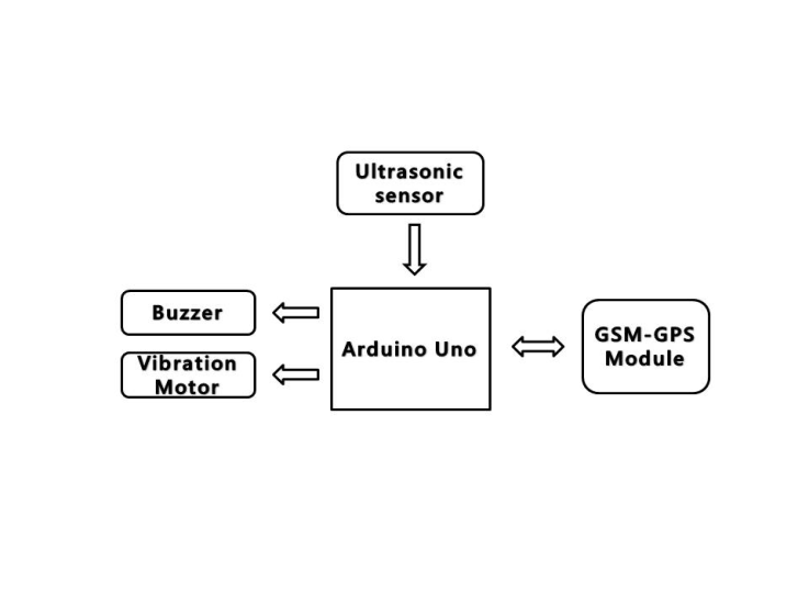 | Figure 1. Block diagram |
4.1. Ultrasonic Sensor Module
- Ultrasonic sensor is used, as, it is less affected by target materials or by colour, it is capable of detecting objects within a range of 4 meter. These ultrasonic sensors are designed to resist external disturbances such as vibration, infrared radiation, ambient noise, and EMI radiation. The sensor used is a SRF-04. It requires a short trigger pulse and it provides an echo pulse. Ultrasonic waves are emitted from the module and bounce back when hits an objects and obstructions in the path of the user. The output of the sensor provides change in voltage with respect to the distance of the obstacle. Also potholes can be detected using this system.
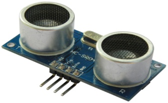 | Figure 2. Ultrasonic Sensor |
4.2. Control Unit
- The control sub-system consists of an Arduino Board having an ATMEGA328P microcontroller merged in it. Arduino is an open-source single board microcontroller, heir of the open-source Wiring platform, thus helping in designing electronics projects easily. The hardware consists of a simple open hardware design for the Arduino board with an Atmel AVR processor and on-board input/output support. The software consists of a standard programming language compiler and the boot loader that runs on the board. The sensor output is provided to an Arduino which calculates the distance based on the program. The obtained value is compared with the fixed value and a vibratory pattern of different intensities is generated.
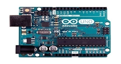 | Figure 3. Arduino Uno |
4.3. Vibration Motor
- A vibration motor is used in the system design, which vibrates with three different intensities depending on the distance from the obstacle. If the obstacle is very near then intensity of the vibration will be very high. Intensity of the motor decreases as the distance of the obstacle increases.
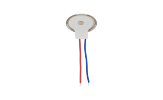 | Figure 4. Vibration motor |
4.4. Buzzer
- A low frequency piezo buzzer is used to indicate that the obstacle is very close to the person and there might be a chance of collision. A buzzer is used along with the vibration motor as an alerting the user in crowded areas.
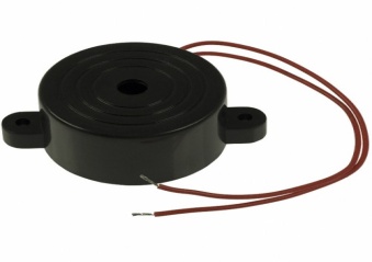 | Figure 5. Buzzer |
4.5. GSM-GPS Modem
- When the GSM modem receives a message the microcontroller will process the message with the keyword saved in it. Then, it will get the location of the stick from the GPS modem and transmit the location to the GSM modem in order to respond to the sender. In case of an emergency, the user of the stick can press the emergency button the microcontroller access the location from the GPS modem and transmit the location to the GSM modem which will send a SMS messages to the saved number in the system.
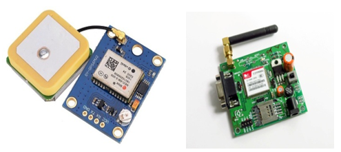 | Figure 6. GPS-GSM module |
5. Implementing the Feedback System
- The device that alerts the user to obstacles in their path is the vibration motor. The motor is housed in the cane, and is connected to the Arduino. The Arduino analyzes data from the ultrasonic sensor, and it is this data that is sent to the vibration motor in the form of a corresponding PWM duty cycle. Depending on the number of pulses, the vibration motor receives varying amounts of power, which causes the vibration motor to spin at differing speeds. These speeds vary discretely instead of continuously, so that a given range of distances will correspond to one vibration intensity. Additionally, each distance will also correspond to a certain delay between vibrations, with greater distances having greater delays.
6. Features
6.1. Detection of Obstacles
- The obstacle detection circuit consists of an ultrasonic sensor interfaced to the Arduino Uno Board. The sensor detects the presence of obstacle in each direction and then the range of the obstacle is calculated. If the distance is within 70cm then vibration motor will be vibrating with highest intensity and also the buzzer will be on. If the distance is between 70cm and 150cm then the vibration motor will vibrate with medium intensity and if the distance is above 250cm then the intensity of the vibration motor will be less.
6.2. Detection of Potholes
- The pothole detection system consists of an ultrasonic sensor and a buzzer interfaced with the Arduino Uno. The working of this circuit is based on the assumption that the height of the ultrasonic sensor mounted on the stick will remain constant in case of a plain path. But if there occurs any noticeable increase in its height from the ground above a certain threshold level then the buzzer will start buzzing. This will help the visually impaired person in detecting a pothole or a staircase ahead.
6.3. Emergency Calling
- The GSM_GPS module is used in emergency situation. This module receives the information from the GPS satellite in NMEA format and transfers the latitude and longitude information as SMS message to a predefined mobile number in case of emergency.
7. Flowchart
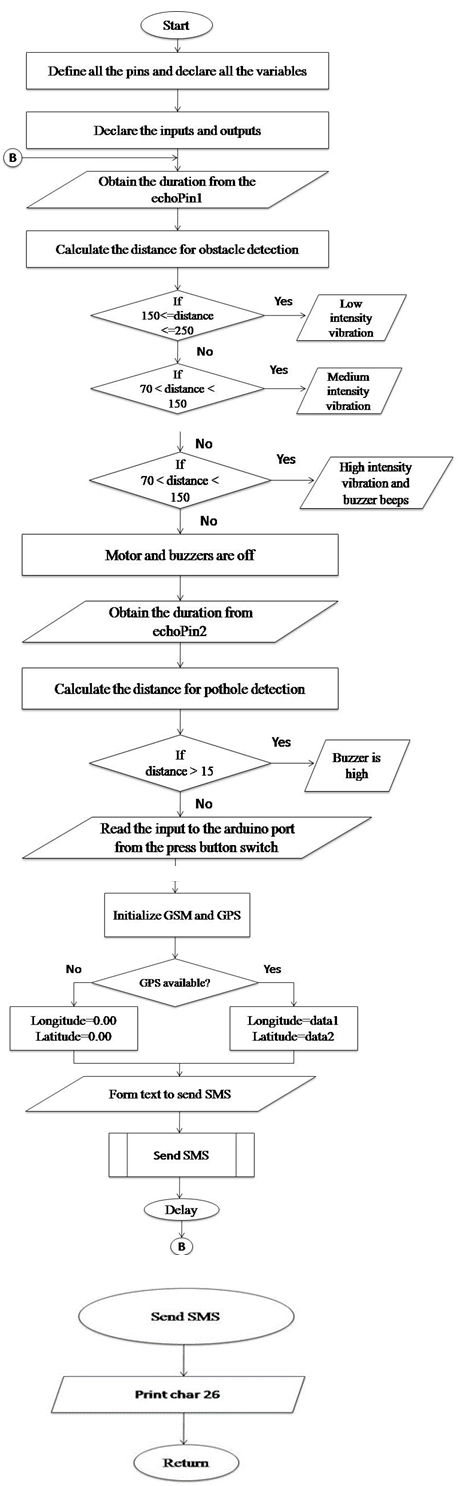 | Figure 7 |
8. Conclusions
- The goal of the smart cane is to bring the white cane up to technological modernity while maintaining its affordable price. The Smart Cane is geared towards an elderly, less affluent demographic group that would demand comfort, accessibility, and affordability from the product. Using the ultrasonic sensor, Arduino board, and vibration motor, the Smart Cane greatly increases the object detection range of the white cane, thereby improving the lives of the visually impaired users. Also the GSM-GPS technology used in the system provides security during emergency situations. Overall, the use of technology provides much more benefits than the white cane, and has taken a great leap towards improving the lives of the visually impaired.
ACKNOWLEDGEMENTS
- We express our sincere gratitude to the Management of our College, St Joseph Engineering College, Mangalore, for providing us an environment with all infrastructure and lab facilities that helped us to finish our project work productively.We also express our heartfelt thanks to Roman and Catherine School for the Blind, for their valuable suggestions.Finally, we would like to thank all those people who have directly and indirectly helped us in our work.