Firas Abdullah Thweny Al-Saedi, Fadi Khalid Ibrahim
Computer Engineering Department, Al-Nahrain University, Baghdad, Iraq
Correspondence to: Firas Abdullah Thweny Al-Saedi, Computer Engineering Department, Al-Nahrain University, Baghdad, Iraq.
| Email: |  |
Copyright © 2014 Scientific & Academic Publishing. All Rights Reserved.
Abstract
This paper discusses a terrain height detection system that is used in a 3-Dimensional (3D) military training environment. Also, a collision check technique is mentioned along with a system that is used to check the collision of an object against the obstacles in the environment in an effective way, that is, checking the collision against the obstacles that the soldier is expected to collide with.
Keywords:
3D, Collision, Terrain height detection
Cite this paper: Firas Abdullah Thweny Al-Saedi, Fadi Khalid Ibrahim, Implementation of Terrain Height Detection and Collision Check Systems in a 3-Dimensional Environment, American Journal of Intelligent Systems, Vol. 4 No. 4, 2014, pp. 148-153. doi: 10.5923/j.ajis.20140404.04.
1. Introduction
Before moving into the subject, one must know what is the Virtual Reality (VR); VR is a computer-simulated environment, whether that environment is a simulation of the real world or an imaginary world. Most current VR environments are primarily visual experiences, displayed either on a computer screen or through special or stereoscopic displays, but some simulations include additional sensory information, such as sound through speakers or headphones. Some advanced, haptic systems now include tactile information, generally known as force feedback, in medical and gaming applications. Users can interact with a virtual environment or a Virtual Artefact (VA) either through the use of standard input devices such as a keyboard and mouse, or through multimodal devices such as a wired glove, the Polhemus boom arm, and omni-directional treadmill. The simulated environment can be similar to the real world, for example, simulations for pilot or combat training, or it can differ significantly from reality, as in VR games. In practice, it is currently very difficult to create a high-fidelity virtual reality experience, due largely to technical limitations on processing power, image resolution and communication bandwidth. However, those limitations are expected to eventually be overcome as processor, imaging and data communication technologies become more powerful and cost-effective over time [1].In this paper and to be cost-effective, Microsoft Visual C# 2008 [2] along with the new XNA 3.0 [3-5] graphics technology released by Microsoft were used, actually, the graphics technology used is games-quality, this technology was used to generate a VR environment that is used individually or through network of two computers (this can be expanded easily). Also, the input device used is either the standard keyboard and mouse or using the new Nintendo Wii Remote (Wiimote) [6, 7]. The terrain generation and height detection are part of the project discussed in this paper, a full content generation can be found in [8]. In addition to the collision detection algorithm discussed here, another algorithm for collision detection in urban environment can be found in [9]. In the next section, the terrain height detection system will be discussed, after that, the collision system and the techniques used to make the collision check faster will be discussed, because, in the simulation, there are a lot of soldiers and enemies along with AI, graphics and calculations, hence, each bit of performance is needed.
2. Terrain Generation and Height Checking
Discussing the terrain generation in detail is a detailed programming issue, so, the paper will not go into the details and it will give a short introduction about how the computer 3D graphics are formed. Each 3D object used is formed of faces, a face is a triangle which can be colored or textured, each face consists of three vertices, a vertex has a 3-axis position (X,Y,Z) where X is right or left, Y is up or down and Z is into the screen or far of screen. Generating the terrains from a small image is the easiest way for this situation where a 128*128 pixel image is drawn with two colors or levels and the terrains are generated in the code by reading each pixel of the image and drawing a vertex on a specified level. Some terrain systems, especially systems used in areas with hills and mountains, use a more-than-two level terrain generator. Here, two simulation environments are used, the first one with two level terrains (grass and cement), the other with three level terrains (grass, cement and pavement). Figure 1 shows the principle of 3D graphics and can be thought as a piece of the terrain field.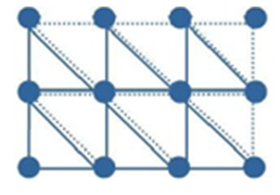 | Figure 1. Vertices and faces |
During the simulation, the position of the 3D object that moves on the terrains is needed so that the program can move it up or down according to height of the terrains below. The problem with this is that the height of the terrains is known only in specific points which are the vertices, what if the object is in an area where it is not on a vertex. In this case, a kind of interpolation is needed. In this paper, the bilinear interpolation is used. For the interpolation, the X and Z coordinates of the vertices around the object's position are needed.Figure 2 shows two faces from the terrain fabric, the object is assumed to be between the two faces, also the four vertices that are around the object's position are shown too. The height of each of those four vertices will be used to find the height of the terrains at the object's position.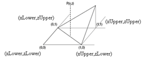 | Figure 2. Two faces from the terrain field |
The process of finding the height is shown in Figure 3 (it is assumed that the object is in the point P(X,Z).After finding the final height, the object's Y coordinate must be assigned to "finalHeigth" in Figure 3. Using this algorithm, the object will move smoothly on the terrains [5].
3. Collision System
After generating the terrains and inserting the 3D objects like houses, helicopters and barrels…etc. a collision system is needed so that the object when moved by the user does not go through the obstacles. There are a lot of methods to define the collision spaces [10], the one used here is by defining bounding boxes and bounding spheres around the obstacles. Bounding spheres and bounding boxes are just data structures that define the properties of the solid area that the object can’t go through. These properties for the bounding sphere are the center position of the sphere and the radius of the sphere. The intersection of this bounding sphere must be continuously checked for intersection with other bounding volumes. The properties needed for the bounding boxes (as shown in Figure 4) are the minimum point coordinates and the maximum point coordinate, using those two points the collision check routine will be able to define the bounding box and check for its intersection with other bounding volumes.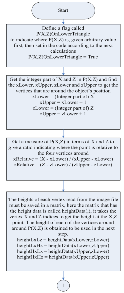 | Figure 3. Flowchart of height detection system |
 | Figure 3. Flowchart of height detection system (continued) |
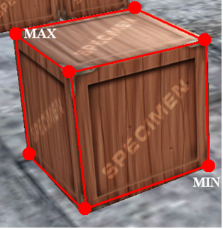 | Figure 4. Bounding box with its minimum and maximum points |
Figure 5 illustrates a collision between two spheres (top view).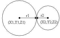 | Figure 5. Collision between two spheres |
To check for the collision between two bounding spheres, the technique in Figure 6 is used.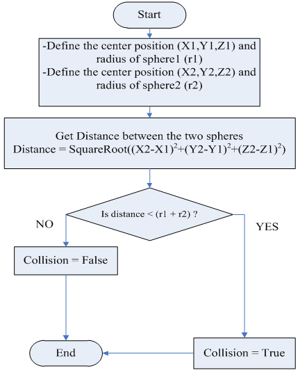 | Figure 6. Flowchart for bounding sphere collision checking |
The collision of two bounding boxes is shown in Figure 7. | Figure 7. Collision between two bounding boxes |
To check for the collision between two bounding boxes, the technique in Figure 8 is used.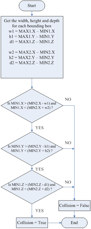 | Figure 8. Flowchart for bounding boxes collision check |
In the simulation, there are a lot of buildings and obstacles, each building has obstacles inside. A method is needed to manage the collision system of the simulation area. A proposed solution to this problem is by creating a data structure for each building added; the data structure of a building will contain the MIN and MAX points of each obstacle inside that building. Moreover, the data structure is made in such a way that enables the designer to group each bunch of obstacles in a group called "collision area". This division process makes the collision check take less CPU cycles to be executed and this will lead to a better performance. According to the proposed system, besides of the inner obstacles data, each building should have an outer bounding box that bounds all the building's borders. The reason beyond using the outer bounding box is to know if the object is in the building and to check its collision to the obstacles of that building only. By this, the object's collision against other obstacles in other buildings will not be checked saving extra work on the CPU. Figure 9 demonstrates the division of a specified floor in a building. 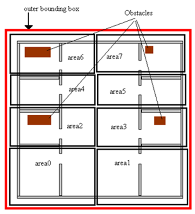 | Figure 9. Division of a floor into areas |
Obviously, each area represents a bounding box that bounds specified obstacles. In the simulation, when the soldier enters a building, the intersection of soldier's bounding box to all areas' bounding boxes of that building will be checked to see in which area the soldier is, then, the soldier's bounding box collision will be checked only against the obstacles that are in that area. For an environment of a lot of soldiers, this is necessary to reduce the CPU cycles used for collision check. Figure 10 demonstrates how the proposed algorithm works.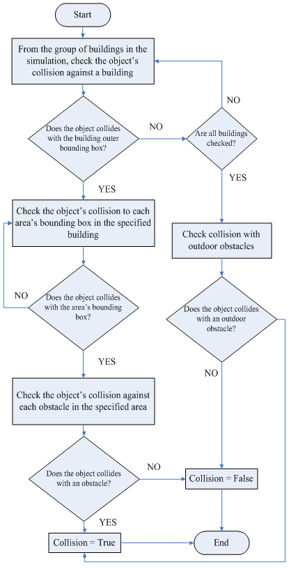 | Figure 10. Flowchart of the collision-check algorithm |
Besides the buildings in the simulation, there exist some outdoor objects like boxes. The collision check system at first must check for the object's collision against buildings as shown in the above algorithm, and then against the outdoor objects.
4. Conclusions
The subjects discussed in this paper are parts from a project that simulates a military environment. The terrain height detection system was used to make the soldiers move smoothly on the terrains. Also, the collision system used is appropriate for the environments designed for the project. But for wider environment, some other algorithms may be used, As an example, dividing the environment itself into areas, so that the object's collision will not be checked against all the buildings in the environment but against the buildings in that area of the environment only. Figure 11 is a snapshot from the simulation environment; different terrain height levels are shown.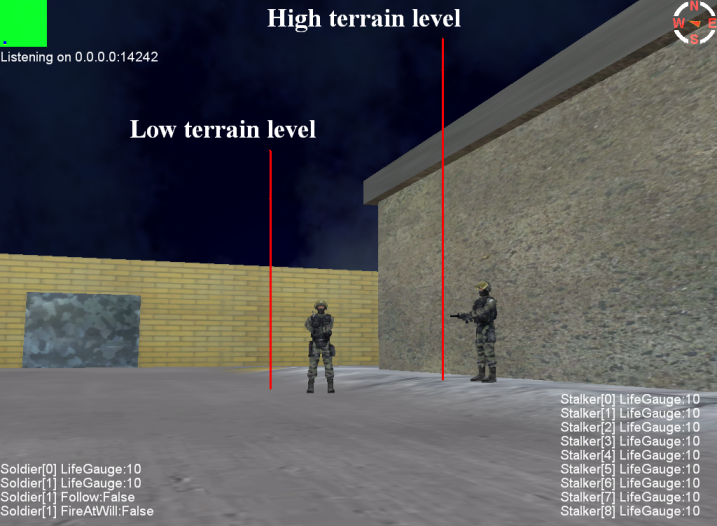 | Figure 11. Two soldiers standing in different terrain height levels |
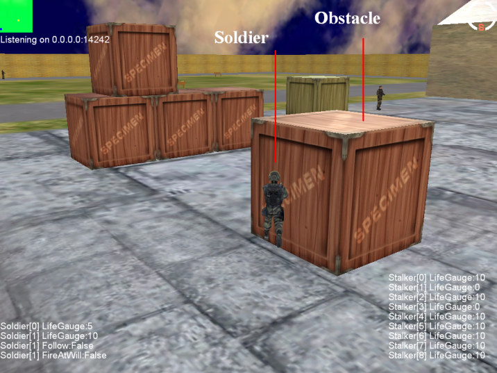 | Figure 12. Illustration of the collision check mechanism |
Also, Figure 12 shows the soldier running to an obstacle but because of the use of the collision check, the soldier stays beside the obstacle and never gets the ability to go through the obstacle.The collision system used is error-free, this means that there is no chance that the soldier will go through an obstacle, the reason for this is that when the user presses a key to move the soldier, only the soldier's position coordinates are updated without drawing the soldier in the new position. When the position coordinates are updated, the collision check routine will check if the soldier with the new position coordinates is colliding with an obstacle and then returns the position coordinates to their old state before updating if there was collision, or, keeps the position coordinates updated if there was no collision. After the collision check, the 3D objects drawing routine will be activated to draw each object in its location based on its position coordinates.
References
| [1] | en.wikipedia.org/wiki/Virtual_reality. |
| [2] | Rob Miles, "C# Developement", Department of Computer Sciences, University of HULL, October 2008. |
| [3] | Aaron Reed, "Learning XNA 3.0", O'Reilly Media, 2009. |
| [4] | Tom Miller, Dean Johnson XNA Game Studio 4.0 Programming. Addison-Wesley, 2010. |
| [5] | Reimer Grootjans, "XNA 3.0 Game Programming Recipes: A Problem-Solution Approach", March 9, 2009. |
| [6] | en.wikipedia.org/wiki/Wii. |
| [7] | www.nintendo.com/consumer/downloads/WiiOpMn_setup.pdf. |
| [8] | Mark Hendrikx, Hendrikx, Sebastiaan Meijer, Joeri Van Der Velden et al., “Procedural Content Generation for Games: A Survey”, Delft University of Technology, the Netherlands, 2012. |
| [9] | Hamzah Asyrani Sulaiman, Mohd Azlishah Othman, Mohd Muzafar Ismail et al., “Quad Separation Algorithm for Bounding-Volume Hierarchies Construction in Virtual Environment Application”, Journal of Next Generation Information Technology (JNIT), Volume 4, Number 3, May 2013. |
| [10] | Ian Millington, "Game Physics Engine Development", CRC Press; second edition, 2010. |
 Abstract
 Reference
 Full-Text PDF
 Full-text HTML