Keietsu Itamiya1, Masataka Sawada2, Daishi Kikuta3, Kohji Toda4
1Department Electrical and Electronic Engineering, National Defense Academy, Yokosuka, 239-8686, Japan
2Doctor Course of Equipment and Structural Eng., NDA, 10-20, Hashirimizu 1-Chome, Yokosuka, Japan
3Azabujuban D Dental Office, Tokyo, 106-0045, Japan
4Professor Emeritus of National Defense Academy, Yokosuka, 239-8686, Japan
Correspondence to: Keietsu Itamiya, Department Electrical and Electronic Engineering, National Defense Academy, Yokosuka, 239-8686, Japan.
| Email: |  |
Copyright © 2012 Scientific & Academic Publishing. All Rights Reserved.
Abstract
This paper presents a new measurement system of three dimensional coordinates based on a multi-link arm and a corresponding precise mathematical model. Model coefficients are estimated beforehand by the PSO method and the joint angle data which are obtained when the multi-link arm tip indicates known calibration coordinates. In the model, especially, deviations from the ideal position of rotation axis are considered. Such uncertainties are identified by offline supervised learning utilizing a PSO method. The proposed method can be regarded as a hybrid measurement method based on hardware and software. Therefore, multi-link 3-D measuring machine as a mechanical system can be produced easily without the need for ultra-precision machining since mechanical uncertainties of the measuring device are built into the model and these will be estimated after offline learning. The effectiveness of the proposed measurement scheme is verified by simple numerical simulation results.
Keywords:
Position Measurement System, Multi-Link Manipulator, Particle Swarm Optimization
Cite this paper: Keietsu Itamiya, Masataka Sawada, Daishi Kikuta, Kohji Toda, A Hybrid Measurement System of Three Dimensional Coordinates by Combination of a Multi-link Manipulator and Particle Swarm Optimization Techniques, American Journal of Intelligent Systems, Vol. 3 No. 2, 2013, pp. 51-56. doi: 10.5923/j.ajis.20130302.01.
1. Introduction
A manipulator type 3D coordinate measurementsystem (CMS)is used in a wide range of fields such as product engineering, surface shape measurement, motion measurement and so on[1-5]. Also, the space where it is used is various; for example, a relatively large space in a measurement for surface shape of vehicle, a narrow space in a jaw motion measurement etc. Most 3D CMSsare composed of a multi-link arm and coordinates identifier. Joint angles information in case the probe at the tip of a link is on a measuring point is sent to anidentifier.Then, the estimate of coordinates is calculated by substituting them to the identification modelcorresponding to the forward kinematic model in Cartesian coordinates system. The accuracy improvement of 3D measurement has been needed increasingly according to the quality improvement demand of a product.However, an estimate of coordinates does not always coincide with the actual coordinatessince links of actual ma-nipulator for 3D CMS cannot rotate like an ideal manipulator. Such an uncertainty depends upon dimension error of components, a change of parts size by temperature orhumidity, a secular change resulting from vibration and so on. This may also depend upon the fact that normal vectors of rotation have displacements from ideal directions. Considerable cost will be required for reducing such an uncertainty. Therefore, it is important to make a mathematical model which matches the actual multi-link manipulator in order to obtain the coordinates estimate as accurate as possible.A many conventional kinematics model for a CMS manipulator is built under the assumption that the normal vector which is the axis of link rotation has an ideal direction. Therefore, the gap between the actual system and the mathematical model is an obstacle to coordinates measurement if a demand performance becomes higher.Several estimation methods for obtaining uncertainties in the 3D measuring instrument model have been proposed [1-5]. However, researches in which uncertainties mentioned above have been taken into account cannot be found. In addition, conventional estimation methods of uncertainties in 3D measuring instrument model were almost linear estimation methods like a least squared method utilizing known teaching coordinates. Therefore, the number of estimates increases explosively when the number of links increases.As a result, the realization of the measurement system becomes difficult because large quantities of teaching coordinates are necessary.Therefore, this paper proposes firstly a new forward kinematics model ofa manipulator for3D coordinate measurementsystem which takes into account inclinations of rotational normal vectors from ideal directions.Then, parameters with respect to those inclinations are estimated by utilizing the particle swarm optimization (PSO) technique and the linkangledata corresponding to the known coordinates for calibration. The rest of the paper is organized as follows.Statement of problem and a new kinematics model are presented in the next section. In section 3, the conventional linear parameter estimation method for a kinematic model and its problem are introduced. The PSO scheme for a 3D CMS is proposedin the section 4. Some numerical simulation results for verifying the effectiveness of proposed scheme are shown in the section 5. The last section concludes the paper.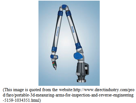 | Figure 1. An example of manipulator for 3D coordinates measurement |
2. New Kinematics Model and Statement of Problem
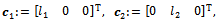
The following simple example gives the motivation of the study.Example:Now consider a two link manipulator. The link 1 rotates around the  -axis of Cartesian coordinates. The 2nd link which is attached to the end of the 1st link rotates on the plane orthogonal to the 1st link. Then, the 3D coordinates
  at the tip of 2nd link can be represented as
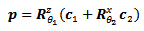 | (1) |
where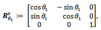 | (2) |
 | (3) |
 | (4) |
 means the measured link angle which can be obtained from link an angle sensor like a rotary encoder,
  is the known link length for
  and
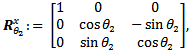
and  are matrices which represent coordinate rotation of
  and
and  around
  -axis and
  -axis respectively. Hence, the initial coordinates of the tip of link 1 is
  . The rotation axis of the link 1 is the
  -axis of Cartesian coordinates. The angle between the
  -axis and the link 1 which rotates counterclockwise is defined as a positive
  . Similarly, the initial coordinates of the tip of link 2 is
 The rotation axis of the link 2 is the link
  . The angle between the
  -planeof Cartesian coordinatesand the link 2 which rotates so as to satisfy
 | (5) |
is defined as a positive  where
where | (6) |
 | Figure 2. Definitions of normal vectors and rotation angles |
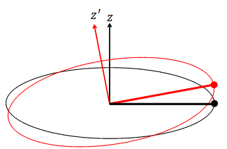 | Figure 3. Link rotation when the normal vector  is deviated from the ideal direction is deviated from the ideal direction  |
Then, the accurate coordinate of the 2nd link tip can be obtained by substituting link angle sensor data to the model(1) when the arm tip is placed to the measurement pointif physical arm equivalent to the model (1) can be produced.However, it is unfortunately difficult even if any expert tries to challenge.Especially, the fact that real rotational normal vectors of arm are different from ideal normal directions cannot be avoided.Thus, the combination of the model (1) and the actual arm may reduce the accuracy of three-dimensional coordinate measurement. A simple solution is to give up the manufacture of an ideal arm and further to construct a precise model corresponding to the actual arm.Then, there exist some positive constants  and
and  such that the following new model generates the exact coordinate when real rotational normal vectors of arm are different from ideal normal directions;
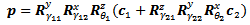 | (7) |
where  is the tip position coordinates of the 2nd link. Parameters
  and
and  represent deviations of normal vectors from ideal directions.
  Therefore, an accurate measurement can be achieved by this model and the corresponding arm if these parameters are known a priori.Also, precisionmodel corresponding to themore complexmulti-link arm like a 6 DOF PUMA manipulator (in which adjacent links are orthogonal to each other. See Fig. 4) for a practical 3D CMS can be constructedsimilarly as
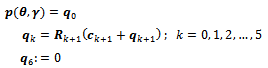 | (8) |
where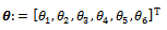 | (9) |
 | (10) |
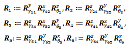 | (11) |
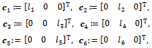 | (12) |
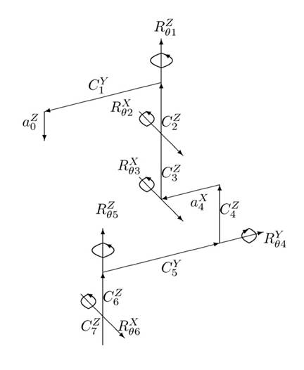 | Figure 4. The definition of rotation direction of each link |
 means the tip position coordinates of the 6th link. Parameters
  , and
, and  represent deviations of the
  normal vectors from ideal directions.Therefore, an accurate measurement can be achieved by the model (6) and the corresponding 6 DOF PUMA manipulator for a practical 3D CMS if parameter vector
  is known a priori.So that, the problem to be considered here is how we identify the unknown vector
  beforehand.
3. Linear Estimation
In order to estimate unknown parameters by using a steepest descent method or a least squares method, it is necessary that the 3D coordinates can be represented as an affine (or a linear) model on unknown parameters. However, (8) does not satisfy such a property, i.e. the coordinates  is nonlinear function on
  . A solution for this problem is an overparameterization technique. For example, when the manipulator consists of 2 links, 3D coordinates of (7) can be overparameterized as follows;
 | (13) |
where 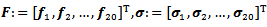 . Defi - nitions of these elements are listed in appendixes. Therefore, if the tip of link 2 can be placed to multiple known points whose coordinates are
 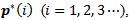 the estimate of
  can be obtained by the following weighted least square on-line method;
 | (14) |
 | (15) |
where  represents estimate of
  in the
  iteration, the design parameter
  satisfies
 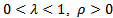 is a small constant.
  is the
  -th known point. Elements of the matrix
  are calculated by using
 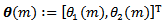 which is the link angle vector when the link tip is placed at
  . (14) minimizes the cost
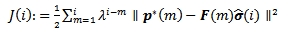 | (16) |
Fig.5 shows simulation results when (14) is used. Parameters for the simulation are set as; 
 .
.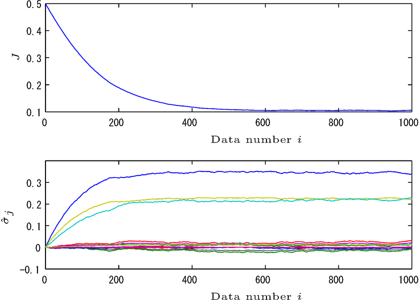 | Figure 5. Response of  and and  using overparametrization and linear estimation using overparametrization and linear estimation |
 but avilable values for estimation include measurement noise (infinitesimal random number).
 From Fig. 3, it can be seen that
  decreases monotonically by updating
  . However, known several hundred coordinates are needed in order to obtain
  small enough.It may lead to divergence of the number of
  in order to obtain good estimates which make
  small enough.Hence, the combination of an overparametrization and a linear estimation is far apart from a practical use in a 3D coordinates measurement.Therefore, in order to solve the problem mentioned above, we will propose a new systemconfiguration forthe3D measurement which uses a multi-link manipulator, the new kinematic model proposed in (7) and a Particle Swarm Optimization (PSO) technique for direct estimation of
  .
.
4. Parameter Estimation Based on PSO for New Kinematic Model
PSO is a computational method that optimizes a problem by iteratively trying to improve a candidate solution with regard to a given measure of quality. PSO optimizes a problem by having a population of candidate solutions, here dubbed particles, and moving these particles around in the search-space according to simple mathematical formulae over the particle's position and velocity. Each particle's movement is influenced by its local best known position and is also guided toward the best known positions in the search-space, which are updated as better positions are found by other particles. This is expected to move the swarm toward the best solutions[9].Therefore, it is suitable for estimating parameters of a precision kinematics model.Let  be the estimate of
  . Now, consider the following cost function
  which evaluates an average distance between
  and
and  in the sense of root mean square.
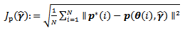 | (17) |
where  means a vector norm which may be the 1-norm, the Euclidean norm or any other norm.Then,
  is a nonlinear function on
  and alsotakes multiple local minimum points on
  since
since  is an argument of trigonometric functions though obtainingan optimal estimateto minimize
  is expected to contribute tothe precise3D coordinates measurement. Therefore, we propose to use the following PSO technique as a parameter estimation method for the new kinematic model (7).Step1 Prepare known
  coordinates;
 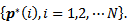 Place the manipulator tip to each
  and storage the corresponding link angle sensor data
  .Step2 Determine the particle number
  and set initial particle
  for
for  . Set the scale
  , the particle update gain
  , the inertia gain
  , correction factors
  and the tolerance
  Step3 For all particle
  , evaluate
  where
where  Then, determineeach particle best
  and the group best
  which satisfy
 | (18) |
 | (19) |
If  then go to Step5 else go to step4.Step4 Update all particle
  and particle’s velocity
  by
by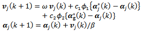 | (20) |
where  and
and  are random number[0, 1]. Go to Step3.Step5 Adopt
  as the optimal estimate of
  , and end the algorithm.We adopted the update law (18) which is a typical PSO algorithm[9] though many modified PSO algorithm[6, 7] are proposed.
5. Numerical Simulation
In order to verify the effectiveness of PSO. Simple numerical simulations were carried out. Fig. 6 shows all particles behavior when the manipulator consists of 2 links where simulation settings are as follows;
 and
and  in the range of
  were produced by utilizing pseud random numbers of PC. Then,
 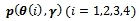 calculated by (7) were used as
  respectively. The proposed algorithm was performed till
  without setting
  .Elements of all particle vectors converged to true values in about 80 times iteration despite
  is only 4.Similar trends have been confirmed by multiple times simulations though the same result cannot be obtained since random numbers are used. Hence, sufficient result was obtained by setting
  in case of 6 links manipulator.
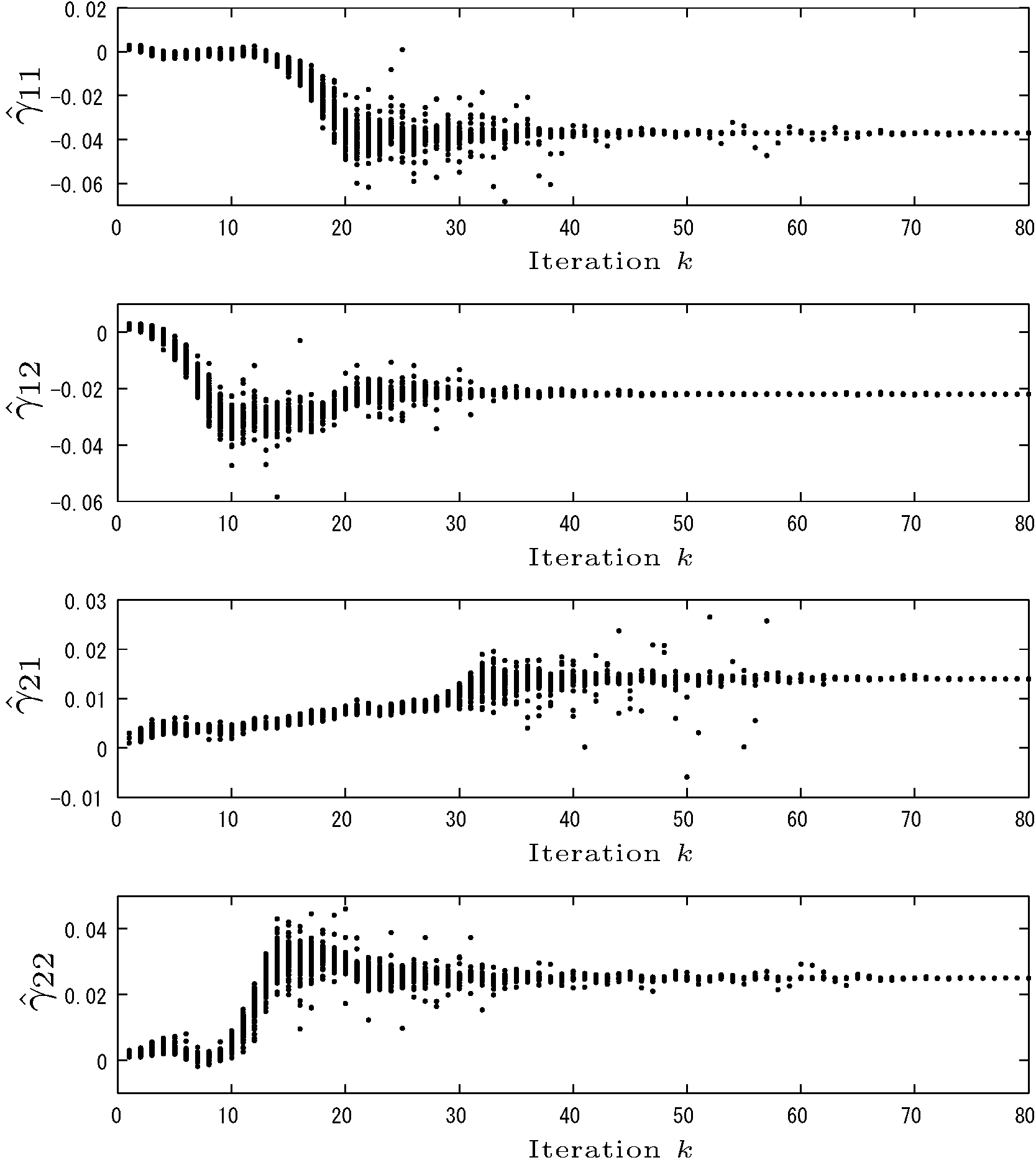 | Figure 6. Simulation example of elements behaviour of all particles in the case of 2 link manipulator |
6. Conclusions
We proposed ahybrid measurement system of three dimensional coordinates by combination of a multi-link manipulator and a new precision kinematics model in which unknown parameters are estimated a priori by a particle swarm optimization techniques.In other words, wehave proposed a method torealize aprecisethree-dimensional measurementsystembythe certain softwareto complement theinaccuraciesof thehardware.The methodproposed here isvery practicalbecausethe parameterscan be estimated precisely with only small number ofcalibration points(the number of required known coordinate is only twice thenumber of links). The effectiveness is verified by simple numerical simulation results. This concept seems to be able to apply to the construction of precise inverse kinematics model of the robot arm for achieving a high precision position control or trajectory control. This is our future study.
Appendix
Basis functions and parameters in theoverparameterization kinematics model (13) for 2 link manipulator are defined as follows;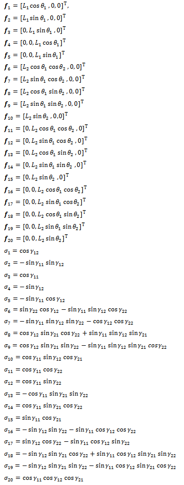
References
| [1] | K. Takamasu and M. Hiraki, Parallel CMM (Coordinate Measuring Machine Using Parallel Mechanism) (Special Issue on Automatic Assembly System), PRECISION ENGINEERING Journal of the International Societies for Precision Engineering and Nanotechnology, vol. 63, no. 12, pp. 1676-1679,1997. |
| [2] | K. Takamasu, M. Abbe, R. Furutani and S. Ozono, Estimation of Uncertainty in Feature Based Metrology (1st Report) : Uncertainty from Systematic Errors in Calibration Process, PRECISION ENGINEERING Journal of the International Societies for Precision Engineering and Nanotechnology, vol. 67, no. 1, pp. 91-95, 2001. |
| [3] | S. D. Phillisp, B. Borchard, W. T. Estler and J. Buttress, The Estimation of Measurement Uncertainty of Small Circular Features Measured by Coordinate Measuring Machines, Precision Engineering, vol. 22, no. 2, pp. 87-97, 1998. |
| [4] | A. Wechenmann, M. Knaner and H. Kunzmann: Infuluence of Measurement Stategy on the Uncertainty ofCMM-Measurements, CILP Annals – Manufacturing Technology, vol. 47, issue. 1, pp. 451-454, 1998. |
| [5] | K. Shimojima, R. Furutani, S. Ozono, K. Takamasu, M. Hiraki and K. Araki, The estimation Method of Uncertainty of Coordinate Measuring Machine (1st Report) : The Estimation of Kinematical Parameter and Uncertainty of Articulated Three-Dimensional Coordinate Measuring, PRECISION ENGINEERING Journal of the International Societies for Precision Engineering and Nanotechnology, vol. 69, no. 6, pp. 841-845,2003. |
| [6] | Chen, Wei-neng; Zhang, A novel set-based particle swarm optimization method for discrete optimization problem, IEEE Transactions on Evolutionary Computation vol. 14, no. 2, pp. 278-300, 2010. |
| [7] | M. Clerc and J. Kennedy, The particle swarm - explosion, stability, and convergence in a multidimensional complex space, IEEE Transactions on Evolutionary Computation, vol. 6, no. 1, pp. 58-73, 2002. |
| [8] | Elshamy, W.,2006,Particle Swarm Optimization Simulation on MATLAB Central.[Online]. Available:http://www.mathworks.com/matlabcentral/fileexchange/11559-particle-swarm-optimization-simulation |
| [9] | For example, Particle swarm optimization on Wikipedia. [Online]. Available:http://en.wikipedia.org/wiki/Particle_swarm_optimization |
| [10] | Mohammad Abdul MUQUIT, Takuma SHIBAHARA, A High-Accuracy Passive 3D Measurement System Using Phase-Based Image Matching, IEICE Transactions FUNDAMENTALS, vol. E89-A, no.3, pp. 686-697, 2006. |
| [11] | Recent Product of 3D Measuring Arm.[Online]. Available: http://www.directindustry.com/prod/mitutoyo/3d-measuring-arms-4906-601538.html, 2013. |
| [12] | AhmetErhan DINC and Fatih PEHLIVAN, Laboratory experiences and 3D measurements with AL5A Robot Arm, A thesis presented tothe Department of Mechanical Engineering Politecnico di Milano, 2011. |
 Abstract
 Reference
 Full-Text PDF
 Full-text HTML