-
Paper Information
- Next Paper
- Previous Paper
- Paper Submission
-
Journal Information
- About This Journal
- Editorial Board
- Current Issue
- Archive
- Author Guidelines
- Contact Us
American Journal of Intelligent Systems
p-ISSN: 2165-8978 e-ISSN: 2165-8994
2012; 2(5): 118-128
doi: 10.5923/j.ajis.20120205.06
Developing a Novel Shared-Clock Scheduling Protocol for Highly-Predictable Distributed Real-Time Embedded Systems
 Abstract
 Reference
 Full-Text PDF
 Full-Text HTML
Mouaaz Nahas
Department of Electrical Engineering, College of Engineering and Islamic Architecture, Umm Al-Qura University, Makkah, KSA
Correspondence to: Mouaaz Nahas , Department of Electrical Engineering, College of Engineering and Islamic Architecture, Umm Al-Qura University, Makkah, KSA.
| Email: |  |
Copyright © 2012 Scientific & Academic Publishing. All Rights Reserved.
The Controller Area Network (CAN) protocol is widely used in the development of distributed real-time embedded systems. It has previously been shown that a “Shared-Clock” (S-C) scheduling algorithm can be used along with CAN protocol to implement time-triggered network architectures. Previous work in this area has led to the development of four S-C scheduling protocols called TTC-SCC1, TTC-SCC2, TTC-SCC3 and TTC-SCC4 schedulers. This paper first reviews the four schedulers. Second, the paper provides a more general model for the TTC-SCC2 scheduler. Third, the limitations of the various S-C schedulers are discussed and an alternative S-C scheduling protocol is developed; which is referred to as TTC-SCC5 scheduler. The five schedulers are then evaluated and compared against a number of criteria including jitter behavior and resource requirements for practical implementation on low-cost embedded microcontrollers. The results presented in the paper show that the TTC-SCC5 scheduler is advantageous over the others since it integrates their key features while maintaining low implementation costs.
Keywords: Time-Triggered, Co-Operative, Shared-Clock, Scheduler, Controller Area Network, Master, Slave, Jitter, Message Latency, Failure Detection Time
Article Outline
1. Introduction
- Over recent years, researchers have considered various ways in which time-triggered software architectures can be employed in low-cost embedded systems where reliability is a key design concern[1,2,3,4,5,6]. Previous work in this area has considered the development of both single- and multi-processor designs. In the case of multi-processor designs, it has been demonstrated that a “Shared-Clock” (S-C) communication architecture – used in conjunction with “Time-Triggered Cooperative” (TTC) scheduling algorithm[7,8] – can provide a simple, flexible and predictable platform for many systems[1]. In such distributed systems, the Controller Area Network (CAN) protocol[9] provides high reliability communication at low cost[10,11,12,13]. CAN has been widely used in automotive and other industrial arenas[10]. As a consequence of its popularity, most modern microcontroller families have members with on - chip hardware support for this protocol (e.g.[14,15,16,17]). CAN protocol can still be an appropriatesolution due to its deep roots in the automotive industry as well as its simplicity, low implementation costs and widespread availability[18]. Moreover, experience gained with CAN over the past years allows the creation of extremely reliable systems using this protocol[19]. However, since CAN is usually viewed as “event-triggered” protocol[20], the use of a S-C architecture in combination with CAN hardware helps to achieve a time-triggered network operation[1].The original S-C scheduling protocols were introduced in 2001 by Michael Pont[1]. In a more recent study[21], a set of possible implementations of the S-C protocol including those presented in[1] were compared and documented. In particular, the study described four S-C scheduling protocols and discussed their strengths and weaknesses. Since each protocol employs a TTC algorithm and a S-C scheduler on top of CAN network, such protocols will be referred to in this paper as “TTC-SCC1”, “TTC-SCC2”, “TTC-SCC3” and “TTC-SCC4” protocols1. Among the four protocols, authors demonstrated that the two protocols “TTC-SCC3” and “TTC-SCC4” provide a better match for the needs of various embedded applications. In our previous studies[22,23], we attempted to improve the timing behavior of the TTC-SCC1 scheduler by proposing a range of data coding techniques which reduce the jitter caused by the CAN hardware bit-stuffing mechanism[10].The present paper reviews the four schedulers in detail and introduces a new (novel) S-C scheduler – referred to here as “TTC-SCC5” scheduling protocol – which attempts to address the key limitations in the previous protocols while achieving high resource efficiency. The paper also provides a more general and flexible model (design) for the TTC-SCC2 protocol for use in wider applications.The remainder of this paper is organized as follows: Section 2 provides an overview of the S-C scheduling architecture. The implementation of this protocol along with TTC scheduler on CAN hardware is discussed in Section 3. Sections 4 - 7 provide overview of the previously developed TTC-SCC1 to TTC-SCC4 schedulers. Section 8 introduces the new TTC-SCC5 scheduler. For all schedulers, strengths and weaknesses are presented just after description of the scheduler in its corresponding section. Empirical results for the purpose of evaluation and comparison of all TTC-SCC schedulers are presented in Section 9. The overall paper conclusion is drawn in Section 10.
2. Shared-Clock (S-C) Scheduler
- The “Shared-Clock” (S-C) architecture, developed in[1], was aimed to provide a simple and low-cost software framework for time-triggered systems without requiring specialized hardware. The S-C scheduler operates as follows (Figure 1). On the Master node, a conventional (co-operative or hybrid2) scheduler operates and the system is driven by periodic interrupts generated from an on-chip timer. On the Slave nodes, a very similar scheduler operates. However, on the Slaves, no timer is used: instead, the Slave scheduler is driven by interrupts generated through the arrival of periodic “Tick” messages sent from the Master node. By doing so, all nodes will be synchronized according to one reference clock (which is the Master clock).
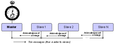 | Figure 1. Simple architecture of Shared-Clock (S-C) scheduler |
3. Time-Triggered Cooperative Shared-Clock CAN (TTC-SCC) Scheduler
- The S-C scheduler can be implemented on a wide range of network protocols used in the design of multi-processor embedded systems, such as CAN, RS-485, TTP and FlexRay. The work presented in this study is, however, focused on implementations using CAN network protocol. The multi-processor systems considered in this study are based on the following three-level implementations:●TTC scheduler implemented in each individual node to achieve time-triggered operations of scheduled tasks.●CAN network protocol implemented as a hardware platform on which the communicating nodes transmit their messages.●S-C scheduling protocol – implemented on top of the CAN – as a software platform to achieve time-triggered communications between the nodes connected in the embedded network.The resulting system is best described as a “TTC-SCC” scheduler (or scheduling protocol). Overall, the use of TTC-SCC scheduler can be so attractive due to its utilization of the error handling features offered by the underlying CAN hardware, whilst – at the same time – allowing the network to behave in a highly-predictable time-triggered manner.
4. TTC-SCC1 Scheduling Protocol
- An overview of the original TTC-SCC scheduler implementation (which is referred to as TTC-SCC1) is presented in this section. The particular implementation discussed in this section is based on that described in detail elsewhere (see:[1,21]).
4.1. Implementation
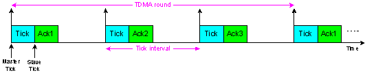
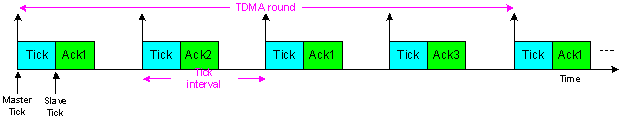
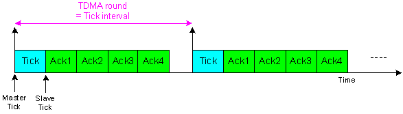
- The TTC-SCC1 scheduler is a simple version of the TTC-SCC scheduling protocol. TTC-SCC1 follows a Time Division Multiple Access (TDMA) protocol in which the Master node communicates with only one Slave node per tick interval. The scheduler is based on the following arrangements: first byte of the transmitted data is reserved for the Slave Identifier (ID) to which the Master “Tick” message is addressed. Only the addressed Slave will reply an acknowledgement “Ack” message to the Master where this message must be sent back within the same tick interval in which the “Tick” message is received. The described mechanism is used by the Master to detect network and node failure. More clearly, at each tick interval, the Master node checks if a valid “Ack” message is received from the addressed Slave in the previous tick. If not, then the necessary actions might be taken, for example, starting a backup Slave, or going into a safe mode. If a correct “Ack” message has been received from that Slave, the Master will send Tick message on the CAN bus which addresses the next Slave node, and so on. Figure 2 below illustrates an example of the TDMA round (cycle) for a TTC-SCC1 network with one Master and three Slaves, where “Tick” messages originate from the Master and the “Ack X” message is transmitted back from “Slave X”. The figure shows that TTC-SCC1 follows a round-robin message scheduling approach in which all Slaves are given equal time to transmit their messages. The figure clearly shows that the TDMA round in the TTC-SCC1 is equal to the number of Slaves multiplied by the width of the tick interval. Given that N is the number of Slaves and T is the tick interval, the TDMA round can be calculated as follows:
 | (1) |
4.2. Strengths
- The TTC-SCC1 is very simple and allows the creation of low-cost, time triggered CAN-based networks with highly predictable patterns of behavior.
4.3. Weaknesses
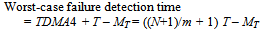
- Slave-to-Slave communication is not permitted as all communication is directed via the Master node (through “Tick” and “Ack” messages). This causes the transmission time of data between any two Slaves to be comparatively long.Also, the time taken to detect the failure of any Slave node can be very long, since the Master checks the status of all Slaves only once per TDMA round. As the TDMA round goes larger, the failure detection time would increase correspondingly. Using Figure 3, where M is the Master Tick message length, the worst-case failure detection time for the TTC-SCC1 scheduler is calculated as:
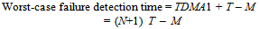 | (2) |
5. TTC-SCC2 Scheduling Protocol
- The TTC-SCC2 scheduler provides a small (but effective) modification to the original TTC-SCC1 scheduler. An overview of the TTC-SCC2 scheduling protocol is presented in this section. The particular implementation discussed in this section is adapted from that which has been described in detail elsewhere[1,21].
 | Figure 2. TDMA round for a four-node system using TTC-SCC1 scheduler |
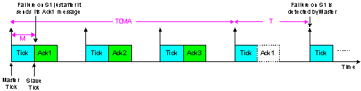 | Figure 3. Failure detection time in TTC-SCC1 |
5.1. Implementation
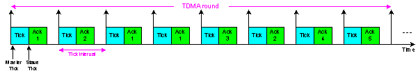
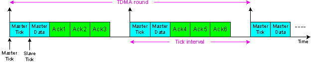
- The round-robin approach used in the TTC-SCC1 scheduler to communicate with the Slave nodes may not be efficient in some networks. For example, in some applications, the Master node may need to communicate with a particular Slave node more frequently than the other Slaves. This is (for example) to check the Slave’s status or acquire some data samples. In order to achieve this, an enhanced implementation of the scheduler is required: this is referred to here as “TTC-SCC2”. The TTC-SCC2 scheduler provides a flexible TDMA round. For example, the status of Slave 1, in the example shown in Figure 2 may need to be checked more frequently than the status of Slave 2 and Slave 3. In this case, the TDMA round used must be amended to meet such an application requirement. An example of appropriate TDMA round that can be used for such a system is illustrated in Figure 4. In the example in the figure, the TDMA round is equal to four tick intervals (i.e. 4T). This can be broken down into 2T (for Slave 1 Ack message which is allowed to transmit twice in the TDMA round) plus 2T (for Slaves 2 and Slave 3 Ack messages, each is transmitted once in the TDMA round). More generally, for N Slaves, the TDMA round can be calculated as follows:
 | (3) |
5.2. Strengths
- The TTC-SCC2 is also very simple and allows the creation of low-cost, time triggered CAN-based networks with highly predictable patterns of behavior.In contrast to TTC-SCC1, the TTC-SCC2 scheduler provides higher flexibility in the way the Master communicates with Slaves, resulting in reduced communication latencies between critical Slaves and the Master. This feature may in turn fulfill the requirements of many real-time applications.
5.3. Weaknesses
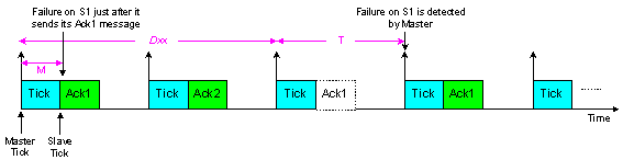
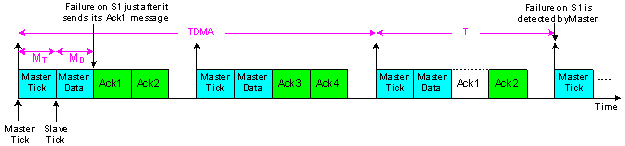
- As with the TTC-SCC1 scheduler, Slave-to-Slave communication is not permitted, causing the transmission time of data between any two Slaves to be comparatively long.Also, the time taken to detect the failure of any Slave node can be very long, since the Master checks the status of some Slaves only once per TDMA round. Using Figure 6, where DXX is the distance between successive ticks allocated for a given Slave, the worst-case failure detection time for the TTC-SCC2 scheduler is calculated as:
 | (4) |
 | Figure 4. A simple TDMA configuration for a four-node system using TTC-SCC2 scheduler |
 | Figure 5. A TDMA configuration for a six-node system with arbitrary pattern using TTC-SCC2 scheduler |
 | Figure 6. Failure detection time in TTC-SCC2 |
 | Figure 7. A simple TDMA configuration for a four-node system using TTC-SCC3 scheduler |
6. TTC-SCC3 Scheduling Protocol
- To resolve some of the outlined shortcomings of the TTC-SCC1 and TTC-SCC2 schedulers, the TTC-SCC3 was developed. An overview of this scheduling protocol is presented in this section. Note that the particular implementation discussed here has been described in detail elsewhere[21].
6.1. Implementation
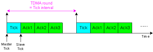
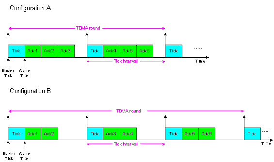
- The TTC-SCC3 scheduler provides the facility for all Slave nodes to transmit their Ack messages within one tick interval. As with TTC-SCC1 and TTC-SCC2, each time a Tick message is sent from the Master, an ID is also sent within the message. However, with TTC-SCC3, this is a “Group ID” (rather than a Slave ID). This simply means that – if there is more than one Slave in a particular group – all Slaves in the group will send their Ack messages simultaneously. In this case, it is the responsibility of the CAN controller to deal with any collision between messages. Thereafter, the Master node needs to ensure that all Slaves in the group addressed in the Tick message have replied back before transmitting the next Tick message, and so on. To better explain the TTC-SCC3 scheduler, assume a four-node system as illustrated in Figure 7. The figure shows how Slave Ack messages can be scheduled in a simple TTC-SCC3 scheduler, where the three Slaves are permitted to transmit in the same tick interval. In this case, the TDMA round is equal to the tick interval.In a more complicated scenario, assume that a system has N Slaves. The scheduler has the option to schedule the Ack messages for all N Slaves in one tick interval, or alternatively divide them between two tick intervals. For example, m Slaves can send Ack messages in the first tick interval while the remaining N-m Slaves send Ack messages in the second tick interval (where m < N). In general, the TDMA in such a scheduler can be extended across multiple tick intervals. Figure 8 illustrates two possible ways to schedule messages in a seven-node system using TTC-SCC3 scheduler. In Configuration A, the TDMA round consists of two tick intervals, each allocated for three Slaves to send their Ack messages. In contrast, the TDMA round in Configuration B is extended across three tick intervals, so that in each interval only two Slaves can send their Ack messages.
 | Figure 8. Two possible TDMA configurations using the TTC-SCC3 protocol for a seven-node system |
 | Figure 9. Failure detection time in TTC-SCC3 |
 | (5) |
 | (6) |
6.1. Strengths
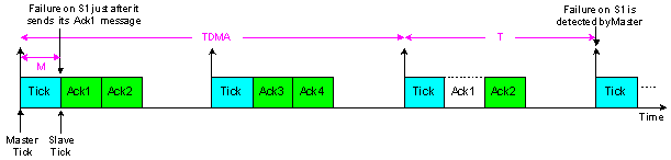
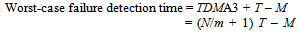
- Failure detection time is reduced. Using Figure 9, where the TDMA round is extended across two tick intervals, the longest possible time for the Master node to detect a failure on the Slave 1 node is calculated as follows:
 | (7) |
6.2. Weaknesses
- As in the TTC-SCC1 and TTC-SCC2 schedulers, tasks running on the Slave nodes will suffer from high jitter due to CAN bit-stuffing in the Master Tick messages.Also, the scheduler requires higher time-bandwidth (i.e. longer tick interval). The tick length depends on the number of Ack messages allowed to transmit per tick interval. This can be a major drawback in applications requiring very small tick intervals.
7. TTC-SCC4 Scheduling Protocol
- The TTC-SCC4 scheduler is another implementation of the S-C algorithm which was adapted from the TTC-SCC3 scheduler. This section describes TTC-SCC4 scheduler briefly. The particular implementation discussed in this section has been described in detail elsewhere[21].
7.1. Implementation
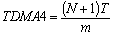
- The motivation behind the development of TTC-SCC4 scheduler is to separate between data messages and time-control messages in order to achieve higher predictability. More specifically, the Master node in a TTC-SCC4 scheduler is set to transmit Tick messages which contain no data. Such messages are used only to synchronize the local time of all other nodes. In another word, the Master node has the responsibility to generate the “heartbeat” of the network and then control the message transmissions over the network. For example, it still has the responsibility to check the status of all Slave nodes and deal with any node-failure. Moreover, it decides which Slaves must transmit in each tick interval if the TDMA round is extended across multiple tick intervals (as in Figure 8). In this case, the Master will use only one data byte for “Group ID” to which particular messages are sent. Figure 10 illustrates how the TDMA round in the system shown in Figure 7 will look like if TTC-SCC4 is used. It can be clearly noticed from the figure that the number of Slaves has increased by one. This implies that the TDMA round in this scheduler is calculated as:
 | (8) |
7.2. Strengths
- Jitter caused by CAN bit-stuffing is minimized. This simple modification to the previous S-C schedulers allows the Tick messages to have short and fixed lengths. Remember that, in any S-C scheduler, Tick messages are sent from the Master at each tick interval to drive the Slave schedulers. If such messages have variable lengths, this is likely to introduce jitter in the timing of tasks running in the Slave nodes.Also, failure detection time is reduced. The results here are very similar to those obtained from the TTC-SCC3 scheduler. The only difference is that the Tick message here is extremely short, therefore the worst-case failure detection time for Slave 1 in the example shown in Figure 9 is calculated as follows:
 | (9) |
7.3. Weaknesses
- To implement such a scheduler in practice, an additional microcontroller will be required as the number of nodes in the system has increased by one. This results in higher implementation costs.As with the TTC-SCC3 scheduler, higher time-bandwidth (i.e. longer tick interval) is required to allow transmission of multiple Ack messages in the same tick.
8. TTC-SCC5 Scheduling Protocol
- Despite the fact that the TTC-SCC4 scheduler helps to substantially reduce the jitter in the Tick messages, the system requires – at least – one additional processor to generate the timing beat of the network. In order to maintain the low levels of jitter without using additional hardware, the TTC-SCC5 scheduler has been proposed. This scheduling protocol is described in this section.
8.1. Implementation
- In the TTC-SCC5 scheduler, the Master is configured to send out two types of messages: Tick messages and Data messages. As with the TTC-SCC4 scheduler, the Tick messages are configured to have “empty” data. This, again, means that these messages are only used to generate the time-reference for the whole network while processing no data. After a Tick message is sent out to all Slaves at each tick, the Master can then send its data in its Data message (see Figure 11). The TDMA round in TTC-SCC5 scheduler is calculated in the same way as in TTC-SCC3 scheduler (i.e. TDMA5 = TDMA3)To implement this scheduler practically, the Master node will have the following CAN message Objects (CMOs): ‘CMO 0’ which is configured to send Master “Tick” messages. ‘CMO 1’ which is configured to send Master “Data” messages.‘CMO 2 – CMO N+1’ which are configured to receive “Ack” messages from N Slaves.
 | Figure 10. A simple TDMA configuration for a four-node system using TTC-SCC4 scheduler |
 | Figure 11. A TDMA configuration for a seven-node system using TTC-SCC5 scheduler |
 | Figure 12. Failure detection time in TTC-SCC5 |
8.2. Strengths
- Since the TTC-SCC5 scheduler is adapted mainly from the TTC-SCC4 scheduler, jitter – caused by CAN bit-stuffing in the Slave ticks is significantly reduced. Failure detection time is also reduced here. Figure 12 illustrates an example where Slave 1 suffers a failure as soon as it has sent its Ack message. If the TDMA round is extended across two tick intervals, the longest possible time that the Master node takes to detect a failure on the Slave node is calculated as follows:
 | (10) |
8.3. Weaknesses
- The scheduler requires more time-bandwidth, as compared to the TTC-SCC3 and TTC-SCC4 schedulers. This is because the Master is requested to send two messages per tick interval (Tick and Data messages). Nonetheless, remember that the Tick message is configured to be as short as possible since it contains no data (unlike the Data message).
9. Evaluation of all TTC-SCC Schedulers
- This section describes the methodology used to obtain the experimental results from the study detailed in this paper. Also, the empirical results from all schedulers are presented in this section.
9.1. Experimental Methodology
- a). Hardware and software setupThe empirical measurements in this study were conducted using Phytec boards supporting Infineon C167 microcontrollers. The C167 is a 16-bit microcontroller with a 20 MHz crystal oscillator. The C167 board has additional on-chip support for CAN protocol. The network consists of four nodes: one Master and three Slaves. The four nodes were connected using a twisted-pair CAN link. The CAN baudrate used was 1 Mbit/sec, and 8-byte “Tick” messages were used, with one byte reserved for the Slave ID, while the remaining data bytes contained random values (except the TTC-SCC4 and TTC-SCC5 schedulers, where Tick messages used only one byte). The tick interval used was 4 ms and the Keil C166 compiler was used[24].The system used is configured to have one task (Master_Task_A) running on the Master node and a corresponding task (Slave1_Task_A) running on Slave 1 node. These tasks are dummy control tasks.b). Jitter testsHere, we assess the jitter levels in the relative timing of Master and Slave ticks in all TTC-SCC networks. Given that “Master_Task_A” sends random data to “Slave1_Task_A” every time it is called, jitter test assesses the variation in the time delay between these two communicating tasks. Note that all other Slaves will receive Master data at the same instant over the CAN link. Moreover, the individual TTC schedulers on each node are based on scheduler implementation presented in[25], where scheduler overheads do not introduce any jitter and, hence, the jitter observed is only caused by the communication protocol.To make transmission delay measurements, a pin on the Master node was set high (for a short period) at the start of the Master task (only task running on the Master). Another pin on the Slave (initially high) was set low at the start of the first task running on Slave 1 (all slaves will receive the Tick message at the same time). The signals obtained from these two pins were then AND-ed (using a 74LS08N chip:[26]), to give a pulse stream with widths that represent the transmission delays. These widths were measured using a National Instruments data acquisition card ‘NI PCI-6035E’[27], used in conjunction with appropriate software LabVIEW 7.1[28]. To represent the results, maximum, minimum and average message transmission times are reported here. To assess the jitter levels, average jitter and difference jitter were reported. The difference jitter is obtained by subtracting the best-case (minimum) transmission time from the worst-case (maximum) transmission time from the measurements in the sample set (this jitter is referred to by other authors as absolute jitter: see[29]). The average jitter is represented by the standard deviation in the measure of average message transmission time. Note that there are many other measures that can be used to represent the levels of task jitter, but these measures were felt to be appropriate for this study.c). Memory testTo reflect the scheduler complexity, the CODE and DATA memory values required to implement each of the described scheduling protocol are recorded. These values are obtained from the “.map” file which is created when the source code of the scheduler is compiled.
9.2. Results
- a). Jitter Table 1 shows the empirical results obtained from the jitter test in all TTC-SCC scheduling protocols.It is clear from the results that TTC-SCC4 and TTC-SCC5 – where Tick messages transmitted from the Master had fixed lengths – jitter was reduced by approximately 80% when compared to the TTC-SCC1, TTC-SCC2 and TTC-SCC3 schedulers. Again, jitter is an important factor which indicates the predictability level of a system. Also, since Master Tick messages sent in the TTC-SCC4 and TTC-SCC5 schedulers had no data bytes, we notice that transmission times in these schedulers were shorter. b). Memory requirementsTable 2 summarizes the memory required to implement all TTC-SCC schedulers discussed in the paper. Note that all slaves would require similar amounts of memory to be implemented on the microcontroller hardware considered in this study.From the results in the table, it is clear that the slaves required the same memory overheads in TTC-SCC1 and TTC-SCC2, and in TTC-SCC3 and TTC-SCC4 schedulers. This is because the Slave codes are identical in each of these cases. In the Master, it can be seen that the memory overheads increased as the scheduler incorporated more features. For example, TTC-SCC5 scheduler required the largest amount of memory overheads to be implemented on the used hardware. However, such increases in memory requirements can still be seen very small (i.e. approx 12% in the ROM and RAM as compared to the basic TTC-SCC1 scheduler).
| ||||||||||||||||||||||||||||||||||||||||||
10. Conclusions
- Over recent years, time-triggered software architectures have received considerable attention. For multi-processor embedded designs, it has been demonstrated that a “Shared-Clock” (S-C) scheduling algorithm can be used along with CAN protocol to implement time-triggered network architectures. The work presented in this paper began by reviewing a set of previously developed S-C scheduling protocols. Despite that such protocols provide reliable solutions for many applications, they suffer some limitations. For example, the TTC-SCC1, TTC-SCC2 and TTC-SCC3 schedulers suffer high levels of transmission jitter which may degrade the performance of many time-critical systems. Moreover, the TTC-SCC1 and TTC-SCC2 schedulers do not allow direct communication between network Slaves, resulting in comparatively long Slave-to-Slave message latencies. To reduce jitter and Slave-to-Slave message latencies, the TTC-SCC4 scheduler was developed. However, such a protocol required one additional microcontroller hardware just to control the network timing, which in turn results in reduced resource utilization. The present paper attempted to address the limitations of the previous schedulers by proposing the TTC-SCC5 scheduler.The implementation of the TTC-SCC5 scheduler was based on scheduling two message types in the Master node during each tick interval: Tick message and Data message. The Tick message had short and fixed length and was only used to generate the time-reference for triggering all salves in the network simultaneously. The Data message was then used by the Master to communicate information to all or particular Slaves. The behavior of the TTC-SCC5 scheduler was compared with the old S-C schedulers in terms of transmission jitter levels and resource requirements. The results presented in the paper show that jitter in the TTC-SCC5 scheduler was reduced by around 80% (like the TTC-SCC4 scheduler). However, the ROM and RAM memory required to implement the TTC-SCC5 scheduler on the used hardware platforms were slightly increased when compared to other schedulers.Overall, the TTC-SCC5 scheduler can be an attractive solution for a wide range of applications. The key advantage of this scheduler is that it provides a reduced jitter characteristic in the message transmission, while maintaining low Slave-to-Slave message latencies and high resource efficiency; having the network timing controlled by one of the existing system nodes without the need for additional hardware (as with TTC-SCC4 alternative). However, the time-bandwidth utilization in such a scheduler is slightly reduced, due to the scheduling of two messages in each tick interval rather than one. It is worth concluding that there is no prefect scheduler implementation which can fit all applications. However, the TTC-SCC5 scheduler proposed in this paper suggests a useful addition to the range of TTC-SCC schedulers. Finally, some important limitations in the reviewed set of TTC-SCC schedulers are discussed in detail elsewhere[21]. Future work in this area includes development of alternative S-C scheduler implementations capable of addressing such limitations. Moreover, future work may include development of mathematical formula for estimating the message latencies between any two communicating nodes in all proposed S-C scheduling protocols. Such work is now under development.
ACKNOWLEDGEMENTS
- The work described in this paper was conducted in the Embedded Systems Laboratory (ESL) at University of Leicester, UK, under the supervision of Professor Michael Pont, to whom the author is thankful. Author would also like to thank Dr. Devaraj Ayavoo for providing the software codes for the TTC-SCC1 – TTC-SCC4 scheduling protocols.
Notes
- 1. TTC-SCC is an abbreviation for Time-Triggered Co-operative, Shared-Clock, CAN. In[21], the four protocols were called “TTC-SC1”, “TTC-SC2”, “TTC-SC3” and “TTC-SC4” schedulers.2. Hybrid scheduler combines cooperative and pre-emptive scheduling, where only one task in the whole system is set to be pre-emptive while other tasks are running co-operatively[1].
References
| [1] | Pont, M.J. (2001) “Patterns for time-triggered embedded systems: Building reliable applications with the 8051 family of microcontrollers”, ACM Press / Addison-Wesley. |
| [2] | Pont, M.J. (2003) “An object-oriented approach to software development for embedded systems implemented using C”, Transactions of the Institute of Measurement and Control, Vol. 25 (3), pp. 217-238. |
| [3] | Pont, M.J. and Banner, M.P. (2004) “Designing embedded systems using patterns: A case study”, Journal of Systems and Software, Vol. 71 (3), pp. 201-213. |
| [4] | Kurian, S. and Pont, M.J. (2007) “Maintenance and evolution of resource-constrained embedded systems created using design patterns”, Journal of Systems and Software, Vol. 80 (1), pp. 32-41. |
| [5] | Wang, H., Pont, M.J. and Kurian, S. (2007) “Patterns which help to avoid conflicts over shared resources in time-triggered embedded systems which employ a pre-emptive scheduler”, Paper presented at the 12th European Conference on Pattern Languages of Programs (EuroPLoP 2007). |
| [6] | Nahas, M. (2011a) "Employing two ‘sandwich delay’ mechanisms to enhance predictability of embedded systems which use time-triggered co-operative architectures", International Journal of Software Engineering and Applications, Vol. 4, No. 7, pp. 417-425. |
| [7] | Baker, T.P. and Shaw, A. (1989) “The cyclic executive model and Ada. Real-Time Systems”, Vol. 1 (1), pp. 7-25. |
| [8] | Locke, C.D. (1992), “Software architecture for hard real-time applications: cyclic executives vs. fixed priority executives”, Real-Time Systems, Vol. 4, pp. 37-52. |
| [9] | Bosch (1991) “CAN Specification Version 2.0”, Robert Bosch GmbH. |
| [10] | Farsi, M. and Barbosa, M. (2000) “CANopen Implementation, applications to industrial networks”, Research Studies Press Ltd, England. |
| [11] | Fredriksson, L.B. (1994) “Controller Area Networks and the protocol CAN for machine control systems”, Mechatronics, Vol.4 (2), pp. 159-192. |
| [12] | Thomesse, J.P. (1998) “A review of the fieldbuses”, Annual Reviews in Control, Vol. 22, pp. 35-45. |
| [13] | Sevillano, J.L., Pascual, A., Jiménez, G. and Civit-Balcells, A. (1998) “Analysis of channel utilization for controller area networks”, Computer Communications, Vol. 21 (16), pp. 1446-1451. |
| [14] | Philips (1996) “P8x592 8-bit microcontroller with on-chip CAN, datasheet”, Philips Semiconductor. |
| [15] | Siemens (1997) “C515C 8-bit CMOS microcontroller, user’s manual”, Siemens. |
| [16] | Infineon (2000) “C167CR Derivatives 16-Bit Single-Chip Microcontroller”, Infineon Technologies. |
| [17] | Philips (2004) “LPC2119/2129/2194/2292/2294microcontrollers user manual”, Philips Semiconductor. |
| [18] | Ayavoo, D. (2006) “The Development of Reliable X-by-Wire Systems: Assessing The Effectiveness of a ‘Simulation First’ Approach”, PhD thesis, Department of Engineering, University of Leicester, UK. |
| [19] | Short, M. and Pont, M.J. (2007) “Fault-Tolerant Time-Triggered Communication Using CAN”, IEEE Transactions on Industrial Informatics, Vol. 3 (2), pp. 13-142. |
| [20] | Leen, G. and Heffernan, D. (2002) “TTCAN: a new time-triggered controller area network”, Microprocessors and Microsystems, Vol. 26 (2), pp. 77-94. |
| [21] | Ayavoo, D., Pont, M.J., Short, M. and Parker, S. (2007) "Two novel shared-clock scheduling algorithms for use with CAN-based distributed systems", Microprocessors and Microsystems, Vol. 31(5), pp. 326-334. |
| [22] | Nahas, M., Pont, M. J. and Short, M. (2009) "Reducing message-length variations in resource-constrained embedded systems implemented using the CAN protocol", Journal of Systems Architecture, Vol. 55, No. 5-6, pp. 344-354. |
| [23] | Nahas, M. (2011b) "Employing two ‘sandwich delay’ mechanisms to enhance predictability of embedded systems which use time-triggered co-operative architectures", International Journal of Software Engineering and Applications, Vol. 4, No. 7, pp. 417-425. |
| [24] | Keil Software (1998) “C166 Compiler, Optimizing 166/167 C Compiler and Library Reference, User Guide”, Keil Elektronik GmbH., and Keil Software, Inc. |
| [25] | Nahas, M., Pont, M.J. and Jain, A. (2004) "Reducing task jitter in shared-clock embedded systems using CAN", In: Koelmans, A., Bystrov, A. and Pont, M.J. (Eds.) Proceedings of the UK Embedded Forum 2004 (Birmingham, UK, October 2004), pp.184-194. Published by University of Newcastle upon Tyne[ISBN: 0-7017-0180-3]. |
| [26] | Texas Instruments (1988) “SN5408, SN54LS08, SN54S08SN7408, SN74LS08, SN74S08Quadruple 2-Input Positive-AND Gates”, available online (Last accessed: July 2012) 74LS08 Datasheet, available on: http://www.cs.amherst.edu/~sfkaplan/courses/spring-2002/cs14/74LS08-datasheet.pdf |
| [27] | National Instruments (2006) “Low-Cost E Series Multifunction DAQ – 12 or 16-Bit, 200 kS/s, 16 Analog Inputs”, available online (Last accessed: July 2012) http://www.ni.com/pdf/products/us/4daqsc202-204_ETC_212-213.pdf |
| [28] | LabVIEW (2007) “LabVIEW 7.1 Documentation Resources”, WWW website (Last accessed: July 2012) http://digital.ni.com/public.nsf/allkb/06572E936282C0E486256EB0006B70B4 |
| [29] | Buttazzo, G. (2005), “Hard real-time computing systems: predictable scheduling algorithms and applications”, Second Edition, Springer. |