American Journal of Intelligent Systems

p-ISSN: 2165-8978    e-ISSN: 2165-8994

2012;  2(5): 93-103

doi: 10.5923/j.ajis.20120205.03

A Biologically Inspired Neural Network for Solar Powered Autonomous Surface Vehicles

Antonio Guerrero-González , Francisco García-Córdova , Inocencio González Reolid , Napoli Gómez Ramirez

Underwater Vehicles Laboratory (UVL), Technical University of Cartagena (UPCT), Cartagena, 30203, Spain

Correspondence to: Antonio Guerrero-González , Underwater Vehicles Laboratory (UVL), Technical University of Cartagena (UPCT), Cartagena, 30203, Spain.

Email:

Copyright © 2012 Scientific & Academic Publishing. All Rights Reserved.

Abstract

This paper describes a neural network model for the reactive behavioural navigation of an autonomous surface vehicle (ASV) in which an innovative, neurobiological inspired sensing control system and a hardware architectures are being implemented. The ASV is used to power and support for a Unmanned Underwater Vehicle (UUV), which incorporates several types of environmental and oceanographic instruments such as CTD sensors, chlorophyll, turbidity, optical dissolved oxygen (YSI V6600 sonde) and nitrate analyzer (SUNA) together with ADCP, side scan sonar and video camera. The ASV gets its energy through solar photovoltaic modules, also has automatic devices for the deployment and collection of underwater robots. Navigation system contains accelerometers, gyroscopes, magnetometers and GPS, to reach an appropriate level of spatial location at all times, and corrects trajectory using a neural control algorithm to process the corresponding corrections.

Keywords: Autonomous Platform Vehicle (ASV), Neural Networks, Obstacle Avoidance, Robot Navigation, Learning Control Adaptive Behaviour, Solar Boats

1. Introduction

The brains of migratory animals builds cognitive maps that guide the seasonal movement using sensors that capture information from the earth, the sun, stars and an internal biological clock[1]. Loggerhead sea turtles (Caretta caretta) may make travels transoceanic sailing longitudinally or from east to west, with no visual landmarks. They do this by magnetic signals[2]. Apparently, they get to navigate thanks to never lose sight of the inclination and intensity of Earth's magnetic field in the form of a "magnetic signature" (see Figure 1), creating a magnetic map in their brains with "bi-coordinate", so, get sailing from east to west, from north to south and in reverse, along their migration routes[3],[4],[5],[6].
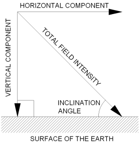
Figure 1. Intensity and inclination of Earth’s magnetic field
The carrier pigeon uses a navigation system similar to the loggerhead sea turtle, when there is not sun, as they have a kind of sun compass, which detect the exact position of the sun at all times[7]. Lobsters (Panulirus argus), are oriented toward their natural habitats by the information obtained from the Earth's magnetic field, which provides information on these sites[8].
The autonomous navigation of robots in unknown environments is one of the most important technological challenges in the field of mobile robotics. The problem arises when a mobile robot is in an unstructured environment, where there are a goal and a number of obstacles[9].
The objective of surface vehicles is to navigate autonomously with its own resources in unstructured environments while avoiding obstacles and reaching the goal. To improve the classical methods of path planning, as visibility graphs, Voroni diagrams[10], are being implemented intelligent control systems based on Artificial Intelligence techniques, Fuzzy Logic[11],[12], and Artificial Neural Networks[13],[14]. These systems are succeeding because of its ability to emulate natural navigation systems of humans and animals.
In this paper, an adaptive artificial neural network to solve problems arising in the navigation of a robotic marine platform will be applied.
We apply a simulation environment using Matlab®, which we will plan the route of the robotic platform and using a neural network method of obstacle avoidance, allow the robotic platform performs the desired path while avoiding obstacles in its path to successfully reach the desired goal. Proposed artificial neural network will be initially trained offline and subsequently online to perform the obstacle avoidance in a more efficient manner.
The platform presents experimental photovoltaic modules, where the energy obtained is stored in batteries, and in addition, the proposed artificial neural network system, also learns to manage power to prevent the robot runs out of energy supply when low sunlight or at night.
There are different projects with the objective of developing an autonomous navigation using photovoltaic solar energy[15]-[16],[17]-[20].
The Cool Robot is an autonomous vehicle designed to navigate in icy environments, such as Antarctica and Greenland, and as supporting scientific research. The energy used is captured by photovoltaic solar modules 160Wp, which carries in its 5 visible faces. The robot weighs 61 kg, and has a maximum speed of 0.78 m/s. The navigation system uses a GPS system, and through an algorithm calculates its position and the destination coordinate, allowing tracing a path to desired goal. Addition, it presents a range of 6 to 8 hours. Also, it can carry about 15kg, at a distance of 500 km, in two weeks[19],[20]. Cool Robot has 4-wheel drive, has solar modules with 54 cells per module and has approximately a dimension of 1.2 m x 1.2 m x 1 m high.
The Microtransat Challenge[16] is a transatlantic race of fully autonomous sailing boats. The race aims to stimulate the development of autonomous sailing boats through friendly competition. The 2012 Microtransat is running for the duration of 2012. Teams may depart at any time during the year. The start line is between 48 and 51 degrees north along the line of 7 degrees and 30 minutes west. Competing teams may depart from any port, providing they cross this line. Additionally the 40 nautical miles preceding the start line must be sailed autonomously. In this competition only allow autonomous ships and that its length does not exceed four meters[16]. The ships will depart from Viana do Castelo, Portugal, and try to reach the coast of the Caribbean. The purpose of this race is to test the strength and reliability of robots in real weather conditions outside the laboratory, and away from battery chargers.
The Pinta ship, developed by the Department of Computer Science at the University of Aberystwyth, United Kingdom, is a robot sailboat of navigation which measures 3.65 meters, weighs 280 kg, has a carbon fibre wing and two solar panels to collect energy from the sun. It is also equipped with ultrasonic sensors, GPS, a computer and a radio-control standard[21].
It is expected that the first robotic ships crossing the ocean, are using the solar energy, without stopping and without assistance. Furthermore, it is believed it will take about three months to reach its goal.
The SAUV II[15] is a solar-powered autonomous vehicle capable of operating on the surface or at water depths up to 500 meters. The vehicle is equipped with rechargeable lithium ion batteries to allow maximum mission endurance even under conditions where minimal solar radiation is available.
Wind is not the only force capable of propelling the machines. A U.S. company, Liquid Robotics[22] has built robots that can move through mechanical conversion of wave energy into forward propulsion[23]. The Wave Gliders has several methods of measurement (Seabird, Datawell, Airmar and Turner Design)[24], is powered by batteries and solar panels for longer mission duration and does not have motors. These instruments take measurements of salinity, turbidity, fluorescence and dissolved oxygen every 10 minutes. This robotic platform consists of two parts. The first is the size of a surfboard and floats on the oceans. The second is under water and is connected to the upper element by means of a cable umbilical. Furthermore, this consists of six pairs of movable wings operated by movement of the waves.
Planet Solar is a solar boat[25], where its energy is obtained from 536 square meters of photovoltaic modules to supply four motors with a power of 92 kW (126 hp). Theses motors generate an average speed of 25 km/h. The PlanetSolar sails during the day with the solar energy and at night with the energy of a pack of batteries.
Turanor is a boat that after 16 months of adventure has been around the world without uttering a single gram of CO2 over its length. This is the largest solar powered boat ever built and with a length of 31 meters by 15 meters wide and with a total weight of 15 tons[25].
Moreover, several papers[26]-[36] examines the application of neural network (NN) to the navigation and control of ASVs using a well-known back-propagation algorithm and its variants since it is not possible to accurately express the dynamics of an ASV as linear in the unknown parameters. Unfortunately, the backpropagation-based NN weight tuning is proven to have convergence and stability problems[36]. Further, an offline learning phase, which is quite expensive, is required with the NN controllers[26],[30] and[37]-[38].
However, mathematical models of neuronal systems are a link between biology and engineering. The Dynamical Neuronal Theory (DNT) builds complex architectures at local (VITE, AVITE), regional (ART, BCS/FCS, MULITIART) and system (DIRECT, FLETE, CEREBELLUM, ...) scale[27] and[39]. Algorithms based on DNT provide reliable adaptive learning models to different architectures depending on the assigned tasks. Auto-organizational neural networks can solve a wide range of problems such as inverse cinematic or reactive and autonomous navigation. Neuro-biologically inspired architectures are based on hierarchical controllers acting in a parallel way.
In this paper, a Self-Organization Direction Mapping Network (SODMN) and a Neural Network for the Avoidance Behaviour (NNAB) both biological inspired are presented. The SODMN is a kinematic adaptive neuro-controller and a real-time, unsupervised neural network that learns to control autonomous underwater and surface vehicles in a non-stationary environment. The SODMN combines an associative learning and a Vector Associative Map (VAM) learning[30] to generate transformations between spatial and velocity coordinates. The transformations are learned in an unsupervised training phase, during which the vehicle moves as a result of randomly selected velocities of its actuators. The controller learns the relationship between these velocities and the resulting incremental movements. The NNB is a neural network based on animal behaviour that learns to control avoidance behaviours in autonomous vehicles based on a form of animal learning known as operant conditioning. Learning, which requires no supervision, takes place as the vehicle moves around a cluttered environment with obstacles. The NNB requires no knowledge of the geometry of the vehicle or of the quality, number, or configuration of the autonomous vehicle’s sensors. Biologically inspired neural networks proposed in this paper represent a simplified way to understand in part the mechanisms that allow the brain to collect sensory input to control adaptive behaviours of autonomous navigation of the animals. This proposed control system based on neurobiological inspired control architecture for autonomous intelligent navigation was implemented on an AUV capable of operating during large periods of time for observation and monitoring. In this work, the autonomy of the vehicle is evaluated in several scenarios
This paper is organized as follows. We first describe (Section II) the experimental platform with the navigation system, neural control system and the set of oceanographic instruments installed on the ASV-UPCT. Section III addresses the experimental results with the proposed control system for control of avoidance and approach behaviour on the ASV-UPCT. Finally, in Section IV, conclusions based on experimental results are given.

2. Description of the Experimental Platform

2.1. Description of the Platform-UPCT

In Figure 2, the experimental platform (ASV) for autonomous surface navigation is shown. This platform has on top a mobile structure with photovoltaic modules. These modules are automatically collected and extend to protect them if the platform is moved by land or by boat, and also when the wind exceeds a certain speed in storms or storm surge.
The experimental platform has also gel batteries, a biodiesel generator, a battery charge controller, a battery charger, the pods and the automatic system for collecting and releasing the underwater robots.
Photovoltaic Modules used is PHOTOVOLTAIC ENECON ITALIA SRL of 130 Wp, made of monocrystalline silicon cells with high performance and flexible. It is used to capture and convert solar radiation into electrical energy. Regulator FLEXmax is used to prevent overcharging of the batteries and prevent discharge to the plates, when no solar radiation.
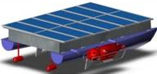
Figure 2. Experimental platform-UPCT
The automatic generator is used when there is a battery power drop due to low radiation or excessive consumption, also when you need an additional power supply.
Accumulators or batteries will be used to store energy from solar photovoltaic modules, and for providing energy in times of low radiation. The platform has the range waterproof gel batteries (VRLA® batteries). In this type of batteries, the electrolyte is immobilized as gel. Gel batteries generally have a longer life and better cycle capacity.
The robot platform uses a converter-charger to convert AC voltage diesel generator output to a DC voltage of 7.2 kW, and 230/400 Vac to 48 Vdc.
The electric diagram of the energy system of the experimental platform is shown in Figure 3. Photovoltaic solar modules are connected to the charge controller, through a protective box. The controller of electrical energy is used to charge batteries. There is also a generator that uses biodiesel fuel, which provides power to 230/400Vac, which after being converted to 48VDC. The charger lets to feed the boat and charge the batteries in the absence of solar energy.
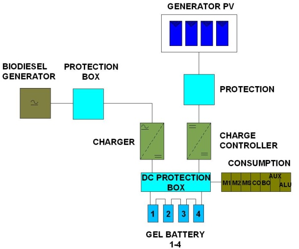
Figure 3. Scheme of the energy installation
Figure 4 shows the connection diagram of the batteries, which are connected in series to obtain 48V. These batteries allow a range of 3 to 4 hours. The batteries are charged with solar modules allowing greater autonomy and in combination with biodiesel generator is allowed to have a long-term autonomy. The interconnection scheme of hardware control system of the experimental platform (ASV) is shown in Figure 5.
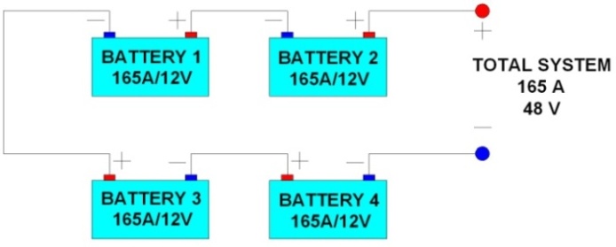
Figure 4. Scheme of connection of the batteries
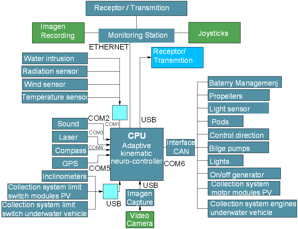
Figure 5. Interconnection elements of hardware control system from the platform-UPCT

2.2. Navigation System of the ASV

The main goal of the navigation system is to achieve an appropriate level of spatial location at all times, allowing trajectory correction using a neural control algorithm, to process the corresponding corrections. Initially, consider three types of missions and each one different positioning procedure.
A global positioning system (GPS) mounted on the vehicle, as usual, will be modified for navigation in shallow waters when long time submerged operation is required. Two options are being considered: a surface-towing buoy with GPS and RF communications system or a kind trolley-pole linked to the buoy when accuracy in location is a critical factor.
When no accurate bathymetry is available or unexpected wreck can be found the proposed neural control algorithm would avoid collision risk.
In deep waters, regular emersions of the vehicle are not feasible, so the neural control system represents the most suitable system to avoid obstacles and allow the spatial location of the vehicle. Using an inertial navigation system combined with the control algorithm and a calibration of positioning bathymetric points of reference, the position of the vehicle is permanently submerged. In this case, it is important to define the benchmarks in the seabed with the utmost accuracy thus allowing the vehicle to find and modify the following path on the basis of these data. In addition, there is being implementing a complementary algorithm to allow the vehicle to be able to search and find the seafloor reference in case of lost the expected location.
In order to save the maximum level of available energy it is mandatory minimizing the number of 'search and find' operations. So it is strongly recommendable to check the course deviation in the study area before each mission. In this way, definition of the local deviation parameters and its use as inputs to calibrate the control system will minimize the tracking deviation.

2.3. Neural Control System

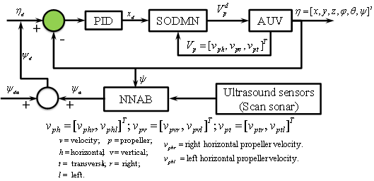
Figures 6 and 7 illustrate our proposed neural architecture. The trajectory tracking control without obstacles is implemented by the SODMN and the avoidance behaviour of obstacles is implemented by a neural network of biological behaviour.
For a dynamic positioning in the path tracking a PID controller was incorporated into the architecture of control system. It allows smooth the error signal in the reaching of objectives.
Figure 6. Neural architecture for reactive and adaptive navigation of an ASV
2.3.1. Self-Organization Direction Mapping Network (SODMN)
The SODMN learns to control the robot through a sequence of spontaneously generated random movements (shown in Figure 6). Random movements enable the neural network to learn the relationship between angular velocities applied at the propellers and the incremental displacement that ensues during a fixed time step. The proposed SODMN combines associative learning and Vector Associative Map (VAM) learning[30] to generate transformations between spatial coordinates and coordinates of propellers’ velocity. The nature of the proposed kinematic adaptive neuro-controller is that continuously calculates a vectorial difference between desired and actual velocities, the ASV can move to arbitrary distances and angles even though during the initial training phase it has only sampled a small range of displacements.
Furthermore, the online error-correcting properties of the proposed architecture endow the controller with many useful properties, such as the ability to reach targets in spite of drastic changes of robot’s parameters or other perturbations.
At a given set of angular velocities the differential relationship between underwater robot motions in spatial coordinates and angular velocities of propellers is expressed like a linear mapping. This mapping varies with the velocities of propellers.
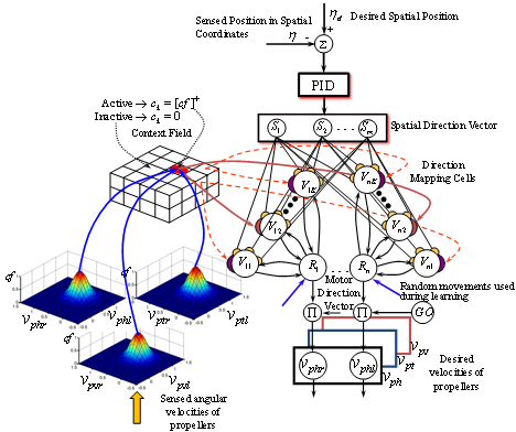
Figure 7. Self-organization direction mapping network (SODMN) for the trajectory tracking of an ASV robot
The transformation of spatial directions to propellers’ angular velocities is shown in Figure 6. The tracking spatial error (e) is computed to get the desired spatial direction vector (xd) and the spatial direction vector (DVs). The DVs is transformed by the direction mapping network elements Vik to corresponding motor direction vector (DVm). On the other hand, a set of tonically active inhibitory cells which receive broad-based inputs that determine the context of a motor action was implemented as a context field. The context field selects the Vik elements based on the propellers’ angular velocities configuration.
A speed-control GO signal acts as a nonspecific multiplicative gate and controls the movement’s overall speed. The GO signal is an input from a center decision in the brain, and starts at zero before movement and then grows smoothly to a positive value as the movement develops.
During the learning, sensed angular velocities of propellers are fed into the DVm and the GO signal is inactive.
Activities of cells of the DVs are represented in the neural network by quantities (S1, S2, …, Sm), while activities of the cells of the motor direction vector (DVm) are represented by quantities (R1, R2, …, Rn). The direction mapping is formed with a field of cells with activities Vik. Each Vik cell receives the complete set of spatial inputs S1, j = 1, …, m, but connects to only one Ri cell (see Figure 6). The mechanism that is used to ensure weights converge to the correct linear mapping is similar to the VAM learning construction[26]. The direction mapping cells 
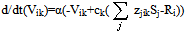
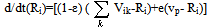
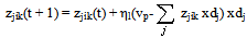
computes a difference of activity between the spatial and motor direction vectors via feedback from DVm. During learning, this difference drives the adjustment of the weights. During performance, the difference drives DVm activity to the value encoded in the learned mapping.
A context field cell pauses when it recognizes a particular velocity state (i.e., a velocity configuration) on its inputs, and thereby disinhibits its target cells. The target cells (direction mapping cells) are completely shut off when their context cells are inactive. This is shown in Figure 6. Each context field cell projects to a set of direction mapping cells, one for each velocity vector component. Each velocity vector component has a set of direction mapping cells associated with it, one for each context. A cell is “on” for a compact region of the velocity space. It is assumed for simplicity that only one context field cell turns “on” at a time.
In Figure 6, inactive cells in the context field are shown as white disks. The center context field cell is “on” when the angular velocities are in the center region of the velocity space, in this three degree-of-freedom example. The “on” context cell enables a subset of direction mapping cells through the inhibition variable ck, while “off” context cells disable to the other subsets. When the kth context cell is "off" or inactive (modeled as ck=0), in its target cells, the entire input current to the soma is shunted away such that there remains only activity in the axon hillock, which decays to zero. When the kth context cell is "on" or active, ck =1, its target cells (Vik) receive normal input.
The DVs cell activities are
(1)
where xd is the desired spatial direction and δ is a gain that controls the integration speed rate.
The Vik cell activities are described as
(2)
where α is a time constant, and zjik are weights of neural network.
The motor direction cell activities are described as
(3)
where vp is sensed velocities of propellers. In the learning phase, the endogenous random generator (ERG) circuit is activated, and ε = 1. During the performance, the ERG circuit is inactive, and ε = 0.
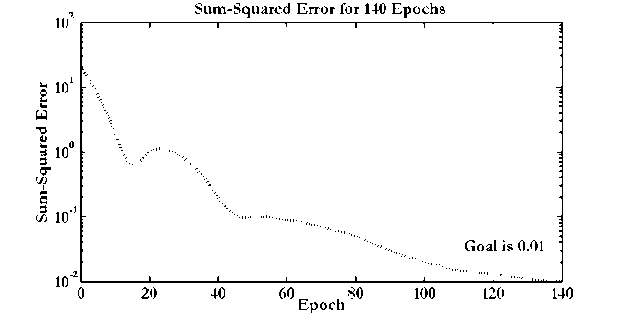
Figure 8. Evolution of the mean square error in the learning phase
The learning is obtained by decreasing weights in proportion to the product of the presynaptic and postsynaptic activities[27]-[30]. Therefore, the learning rule can be obtained by using the gradient-descent algorithm. The training is done by generating random movements, and by using the resulting angular velocities and observed spatial velocities of the AUV robot as training vectors to the direction mapping network. The weights of network are obtained as
(4)
where ηl is learning rate and is a positive constant gain.
The Figure 8 shows the evolution of the error in the learning phase.
2.3.2. Neural Network for the Avoidance behavior (NNAB)
The obstacle avoidance adaptive neuro-controller is a neural network that learns to control avoidance behaviours in an ASV robot based on a form of animal learning known as operant conditioning. Learning, which requires no supervision, takes place as the robot moves around a cluttered environment with obstacles. The neural network (shown in Figure 8) requires no knowledge of the geometry of the robot or of the quality, number, or configuration of the robot’s sensors. Our implementation is based in the Grossberg’s conditioning circuit, which follows closely that of Grossberg & Levine[40], Chang & Gaudiano[41] and[42].
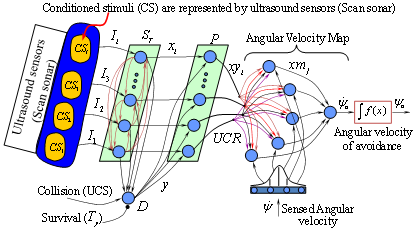
Figure 9. Neural network for the avoidance behavior (NNAB)
In this model the sensory cues (both conditioned stimuli (CS) and unconditioned stimuli (UCS)) are stored in Short Term Memory (STM) within the population labeled ST, which includes competitive interactions to ensure that the most salient cues are contrast enhanced and stored in STM while less salient cues are suppressed. The population ST is modeled as a recurrent competitive field in simplified discrete-time version, which removes the inherent noise, efficiently normalizes and contrast-enhances from the ultrasound sensors activations. In the present model the CS nodes correspond to activation from the robot’s ultrasound sensors. In the network Ii represents a sensor value which codes proximal objects with large values and distal objects with small values. The drive node (D) corresponds to the Reward/Punishment component of operant conditioning (an animal/robot learns the consequences of its own actions).
Learning can only occur when the drive node is active. Activation of drive node (D) is determined by the weighted sum of all the CS inputs, plus the UCS input, which is presumed to have large, fixed connection strength. The drive node is active when the robot collides with an obstacle, which could be detected through a collision sensor, or when any one of the proximity sensors indicates that an obstacle is closer than the sensor’s minimum range. Then the unconditioned stimulus (USC) in this case corresponds to a collision detected by the mobile robot. The activation of the drive node and of the sensory nodes converges upon the population of polyvalent cells P. Polyvalent cells require the convergence of two types of inputs in order to become active. In particular each polyvalent cell receives input from only one sensory node, and all polyvalent cells also receive input from the drive node (D).
Finally, the neurons (xmj) represent the response conditioned or unconditioned and are thus connected to the motor system. The motor population consists of nodes (i.e., neurons) encoding desired angular velocities of avoidance, i.e, the activity of a given node corresponds to a particular desired angular velocity for the ASV robot. When driving the robot, activation is distributed as a Gaussian centered on the desired angular velocity of avoidance. The use of a Gaussian leads to smooth transitions in angular velocity even with few nodes (see Figure 10).
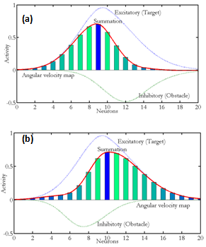
Figure 10. Positive Gaussian distribution represents the angular velocity without obstacle and negative distribution represents activation from the conditioning circuit. The summation represents the angular velocity that will be used to drive the robot
The output of the angular velocity population is decomposed by SODMN into angular velocities of left and right horizontal thrusters. A gain term can be used to specify the maximum possible velocity. In NNAB the proximity sensors initially does not propagate activity to the motor population because the initial weights are small or zero. The robot is trained by allowing it to make random movements in a cluttered environment. Specifically, we systematically activate each node in the angular velocity map for a short time, causing the robot to cover a certain distance and rotate through a certain angle depending on which node is activated.
2.3.3. Set of Oceanographic Instruments Installed on the ASV
In order to provide a wide range of oceanographic research capabilities, the ASV-UPCT was equipped with several types of environmental and oceanographic instruments[43]. This allows the vehicle to carry out different types of missions, depending on research interests or needs. Two main areas of study with different results are supported by the vehicle operation: Shallow- and open-water missions.
Figure 11 shows the location of the areas chosen for both type of missions: The Mar Menor coastal lagoon for shallow water missions and the shelf-break off Cape Tiñoso, both located in the Region of Murcia (Spain).
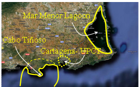
Figure 11. Map representing both research areas. Aerial view of the Mar Menor Lagoon and Cape Tiñoso in Cartagena-Murcia, Spain
Shallow-water missions: To carry out this kind of studies the Mar Menor coastal Lagoon has been chosen. The Mar Menor is a hypersaline coastal lagoon located in the Region of Murcia (Spain) in the South Western Mediterranean Sea. Their special ecological and natural characteristics make the lagoon a unique natural, being the largest lagoon in Europe. Its General characteristics are: 6-10 meters max. depth, 135 Km2 area, 2.5m mean depth and 42-49 P.S.U. salinity. Figure 9 and Figure 12 shows the Mar Menor Lagoon.
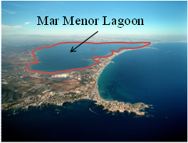
Figure 12. Location of the study zone. Aerial view of the Mar Menor lagoon, in Murcia, Spain
Three different mission will be developed in this environment: 1) Water quality monitoring: Using a YSI® multiparametric sonde (measuring temperature, salinity, turbidity, chlorophyll, dissolved oxygen) and a SUNA® nitrates analyzer together with an ADCP (SONTEK®) measuring currents (speed and direction). 2) Mapping: to perform high resolution bathymetries – using sonar side scanner (TRITECH®), and submerged vegetation maps using video cameras. 3) Data acquisition in order to validate high resolution 3D hydrodynamic models.
Open Water Missions: Oceanographic processes on the shelf-break off Cape Tiñoso have been chosen as case study. The area is close to Cartagena reaching 300-500 m depth in less than 6 miles off-shore with an easy access to deep water (2500 meters). In the area upwelling currents meet surface currents with high productivity thus allowing a high fisheries effort. In a first phase measurements of temperature, salinity, current velocity and direction (specially in the vertical) will be performed. Figure 13 shows area on the shelf-break where the major fisheries effort (dots) is made.
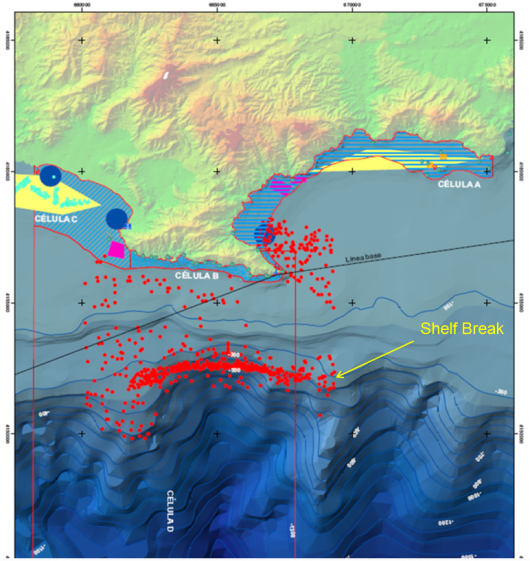
Figure 13. Shelf-break off Cape Tiñoso. Red dots mean position where local fisheries effort is carried out

3. Experimental Results

3.1. Proposed Control System for the ASV Robots

The proposed neural network model is capable of generating optimal trajectory for ASVs in an arbitrarily varying environment. The state space is the Cartesian workspace of ASV. The tests of the proposed control system were carried out under a simulation (real) environment.
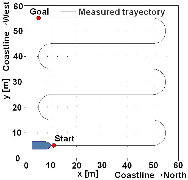
Figure 14. Trajectory tracking of the experimental platform
The simulation environment for the navigation of the robotic platform was represented by a Cartesian space represented by a square of 60x60 meters and mapped on an image of 240 x 240 pixels, as shown in Figure 14, where each pixel corresponds to real 25cm. The desired path is 240 meters, with six straight 40-meter, three left turns and two rights. In this environment, it traces the desired trajectory for the robotic platform, and in addition are placed obstacles that the robot will have to avoid.
The ASV control variables are the coordinates (x, y) and angle (φ) representing the position and orientation within the environment, respectively. The initial and final coordinates are represented (xi, yi) and (xf, yf), respectively. Moreover, the desired trajectories are plotted on this Cartesian coordinate system.
The results of the tracking error (ex, ey) are shown in Figure 15.
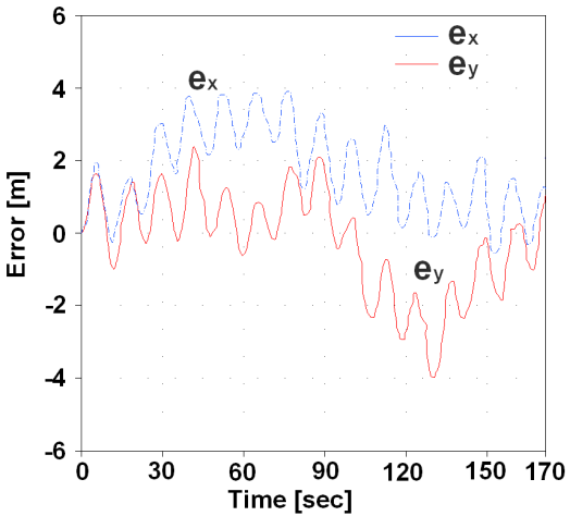
Figure 15. Tracking error of the experimental platform
In Figure 16 shows the phase shift of the ASV orientation on the first line of 40 meters and the first turn left. Is noted as the offset the orientation becomes 0 to 8 seconds, due to the inertia of the water that slows the movement and rotation of the experimental platform.
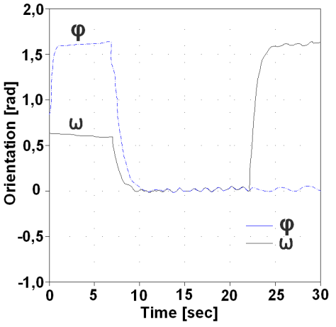
Figure 16. Orientation of the experimental platform
In Figure 17 shows the speed (vx, vy) of the ASV, during the path of its trajectory of 240 meters, the straight-line speed is 2m/sy during turns of 1m / s. The ASV carried out the path of its trajectory in 170 seconds.
The ASV is equipped with ultrasonic sensors distributed on their front and a laser scanning sensor placed on the centre front. These sensors detect the presence of obstacles and measure the distance to which they are located. Furthermore, these sensors determine whether the obstacles are static or moving, and measure the speed and direction of these.
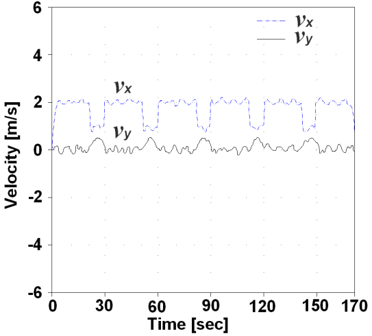
Figure 17. Velocity of the experimental platform
Also, ASV is equipped with radiation sensors, a pyranometer[44] or calibrated photovoltaic cell, level charge battery sensors, energy consumption sensors for the power management system.
The ASV has a global positioning system (GPS)[45], to locate the platform as accurately as possible, taking into account the energy available for power management system. This system at all times checks radiation incidence, the stored energy, and consumption of sensors and actuators.
In the case of low radiation, ASV reduces the consumption of their systems and initially reduces the speed of navigation, in the case of very low energy of batteries, the control system for power management may choose to stop or starting the biodiesel generator, in this case, the automatic collection system of photovoltaic modules would start up.

3.2. Trajectory Generation Training

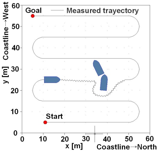
The proposed neural network system was trained off-line with different types of trajectories with and without obstacles. After training, the first paths and targets were simulated on an environment without obstacles, where the ASV presented favourable results for the orientation, trajectory and desired goal.
In the simulation environment was set a desired trajectory to follow and has added a number of mobile obstacles, which may represent boats that crosses the desired path of the ASV and moves with a speed and specific direction.
The robot detects the boat as an obstacle, early enough, and calculates its direction and speed. Then the control system proceeds to change the trajectory of ASV to avoid the obstacle and finally returns to the desired path, to continue the indicated exploration mission, as shown in Figure 18. This figure shows the trajectory generated by the ASV in dotted lines.
Figure 19 shows the simulation of a desired trajectory for the ASV with moving objects, which can be two boats that cross in the trajectory of the ASV. During simulation, the robot proceeded to avoid the obstacles, with increasing accuracy, because the learning of the neural control system proposed also what performed on-line.
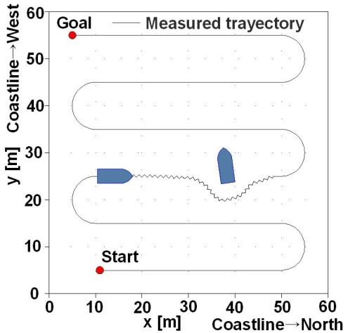
Figure 18. Trajectory followed by the experimental platform in presence of obstacles
Figure 19. Obstacles avoidance trajectory
In Figure 20 shows the result of the trajectory of different targets in reaches. The red line shows the path made by the ASV. The sequence of reach is from StartàT1àT2àT3 and T3àT1. The red line shows the path made by the ASV.
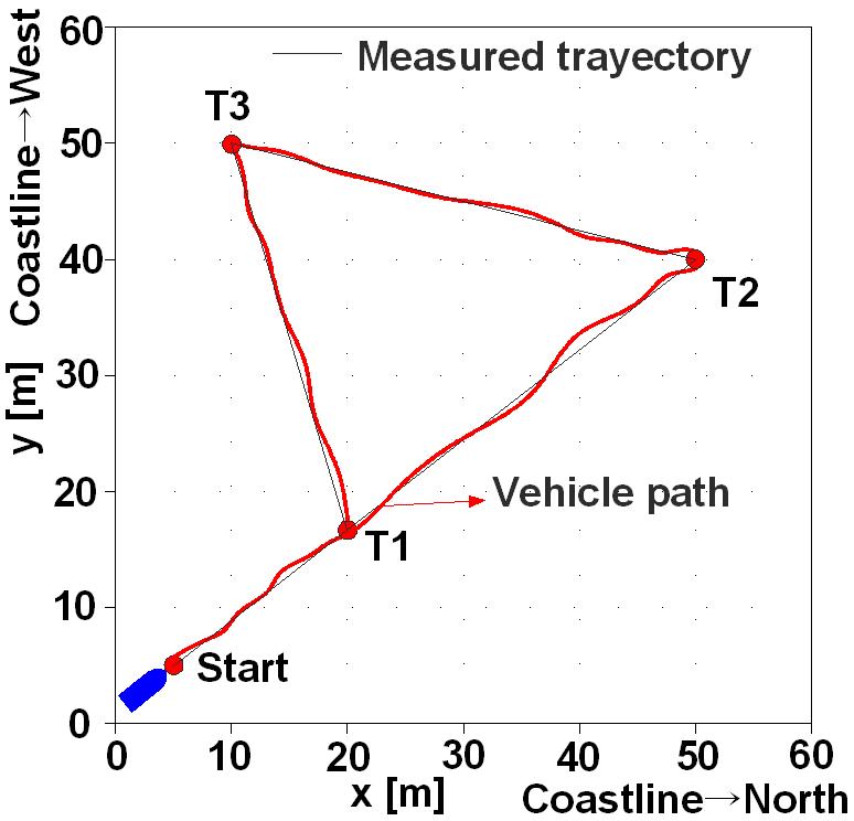
Figure 20. Trajectory of the reach from experimental platform

4. Conclusions

In this paper, a library of training patterns for off-line learning of the proposed neural network has been developed on a simulation environment using Matlab®. These training patterns were generated with several randomly trajectories in an environment with static and moving obstacles. In the simulation, different obstacles by varying the size, speed and direction were used. Various disturbances under simulation to create an unstable environment of the ocean by changing conditions of sea currents, wind, storm, or waves were incorporated into the control system.
The robotic platform (ASV-UPCT) has sonar and laser sensors for obstacle detection, radiation sensors and power consumption for energy management, and a GPS for tracking the desired trajectory.
The SODMN learns to control the robot through a sequence of spontaneously generated random movements. The random movements enable the neural network to learn the relationship between angular velocities applied at the propellers and the incremental displacement that ensues during a fixed time step. Furthermore, the nature of the proposed kinematic adaptive neuro-controller is that continuously calculates a vectorial difference between desired and actual velocities, the ASV can move to arbitrary distances and angles even though during the initial training phase it has only sampled a small range of displacements.
Also, the obstacle avoidance adaptive neuro-controller is a neural network that learns to control avoidance behaviours in the ASV robot based on a form of animal learning known as operant conditioning. Learning, which requires no supervision, takes place as the robot moves around a cluttered environment with obstacles. This neural network requires no knowledge of the geometry of the robot or of the quality, number, or configuration of the robot’s sensors.
The ASV-UPCT has a magnetic compass, which works as a complement to the integrated GPS for a navigation and positioning more fully. Also, it has additional sensors which measure the carbon dioxide content of the water, the degree of contamination of it, the air pressure, wind speed or temperature of the oceans. The data obtained provides valuable information. On the other hand, this boat robot can control and monitor events such as accidental oil spills.
Furthermore, this is able to follow a path without human assistance, while it takes samples used for scientific research on climate change or chemical composition of the oceans. Also, it provides energy and provides support for autonomous underwater vehicles (AUV-UPCT)[46].

ACKNOWLEDGEMENTS

Authors thanks the Spanish Navy for kindly made over the vehicle to UPCT to its re-construction for environmental and oceanographic studies. This project is in part supported by Coastal Monitoring System for the Mar Menor (CMS- 463.01.08_CLUSTER) project founded by Regional Government of Murcia and by BUSCAMOS project (Design of an Autonomous Experimental Platform Solar Powered for Inspections and Oceanographic Mission-UPCT: DPI-2009-14744-C03-02) founded by Spanish Ministry of Science and Innovation from Spain.

References

[1]  Mª. L. Fanjul de Moles and Aldi de Oyarzábal, “Navegación animal”. Investigación y Ciencia, diciembre de 2007.
[2]  Nathan F. Putman, Courtnet S. Endres, Catherine M. F. Lohmann and K. J. Lohmann, “Longitud Perception and Bioordinate Magnetic Maps in Sea Turtles”. Current Biology 21, 463-466, March 22, 2011.
[3]  Lohmann, K. J. & Lohmann, “Detection of magnetic inclination angle by sea turtles: a possible mechanism for determining latitude”. Journal of Experimental Biology 194: 23-32. C. M. F. 1994.
[4]  Lohmann, K. J. & Lohmann, “Detection of magnetic field intensity by sea turtles”. Nature, 380: 59-61. C. M. F. 1996.
[5]  Lohmann K. J., Hester, J. T. & Lohmann, “Long-distance navigation in sea turtles”. Ethology Ecology & Evolution, 11: 1-23. C. M. F. 1999.
[6]  Lohmann, K. J., Cain, S. D., Dodge, S. A. & Lohmann, “Regional magnetic fields as navigational markers for sea turtles”. Science, 294: 364-366. C. M. F. 2001.
[7]  S. D. Cain, L. C. Boles, J. H. Wang, and K. J. Lohmann, “Magnetic Orientation and Navigation in Marine Turtles, Lobsters, and Molluscs: Concepts and Conundrums, ” Integrative and Comparative Biology, vol. 45, no. 3, pp. 539 –546, Jun. 2005.
[8]  W. Wiltschko and R. Wiltschko, "Magnetic orientation in birds," *Journal of Experimental Biology*, vol. 199, no. 1, pp. 29 -38, Jan. 1996.
[9]  Mª C. Marcos provecho, R. Guzmán Martínez y R. Alaíz Rodriguez, “Autoguiado de robots móviles mediante redes neuronales”. Escuela de Ingenierías Industrial e Informática, Dpto. Ingeniería Eléctrica y Electrónica. Universidad de León. XXV Jornadas de Automática, Ciudad Real, del 8 al 10 de septiembre de 2004.
[10]  A. Ollero Baturone, “Robótica Manipuladores y robots móviles”, Ed. Marcombo. ISBN: 84-481-0815-9. 2001.
[11]  R. Brooks, “A Robust Layered Control System for a Mobile Robot”. IEEE Journal or Robotics and Automation, Vol. RA-2, Nº1, pp 14-23.
[12]  N. Nilsson, “Inteligencia Artificial: una nueva síntesis”. Ed. McGraw-Hill. ISBN 84-481-2824-9. España 2001.
[13]  R. J. Mitchell and D. A. Keating, “Neural Network Control of Simple Mobile Robot”. Department of Cybernetics. The University of Reading. Reading, UK.
[14]  Yan Zhou, D. Wilkins and Robert Cook, “Neural Networt Control for A Fire-Fighting Robot”. University of Mississippi. Dept. of Computer and Information Science.
[15]  “Solar Powered Autonomous Underwater Vehicle, FSI SAUV II”. Falmouth Scientific, Inc. 1400 Route 28ª, pobox 315, Cataumet, MA 02534-0315, septembre 2004, 2008 and 2009.
[16]  http://www.microtransat.org/index.php?lang=en
[17]  P. Forde Rynne. “Design & performance og wind and solar-powered autonomous surface vehicle”. Thesis for the Degree of Master of Sciencie. Florida Atlantic University. December 2008.
[18]  A. Lammas, K. Sammut, F. He. “6-DoF Navigation Systems for Autonomous Underwater Vehicles”. Flinders University Australia.
[19]  R. McEwen, H. Thomas, D. Weber, F. Psota. “Performance of an AUV Navigation System at Arctic Latitudes”. Monterrey Bay Aquarium Research Institute, Kearfott Guidance and Navigation Corporation. October of 2001.
[20]  L. E. Ray, J. H. Lever, A. D. Streeter. “Performance of a Solar-Powered Robot for Polar Instrument Networks”. Thayer School of Engineering, Dartmouth College Hanover, Cold Regions Research and Engineering Laboratory U.S. Army ERDC, Hanover.
[21]  http://www.aber.ac.uk/en/cs/news-archive/2010/title-97105-en.html.
[22]  http://liquidr.com/.
[23]  R. Hine, S. Willcox, G. Hine, and T. Richardson, “The Wave Glider: A Wave-Powered autonomous marine vehicle,” in OCEANS 2009, MTS/IEEE Biloxi - Marine Technology for Our Future: Global and Local Challenges, 2009, pp. 1–6.
[24]  Manley, J.; Willcox, S.; , "The Wave Glider: A New Concept for Deploying Ocean Instrumentation," Instrumentation & Measurement Magazine, IEEE , vol.13, no.6, pp.8-13, December 2010.
[25]  http://www.planetsolar.org/.
[26]  Li, Z.X., Bui, T.D.: Robot path planning using fluid model. J. Intell. Robot. Syst., 21 (1998) 29-50.
[27]  Ritter, H.J., Martinez, T.M., Schulten, K.J.: Topology-conserving maps for learning visuo-motor coordination. Neural Networks 2 (1989) 159-168.
[28]  García-Córdova, F.: A cortical network for control of voluntary movements in a robot finger. Neurocomputing 71 (2007) 374-391.
[29]  García-Córdova, F., Guerrero-González, A., Marín-García, F.: Design and implementation of an adaptive neuro-controller for trajectory tracking of nonholonomic wheeled mobile robots. In Mira, J., Álvarez, J.R., eds.: Nature Inspired Problem-Solving Methods in Knowledge Engineering, Lectures Notes in Computer Science. Volume 4528. Springer-Verlag Berlin Heidelberg, LNCS- 4528, Part II, ISBN: 978-3-540-73054-5 (2007) 459-468.
[30]  Gaudiano, P., Grossberg, S.: Vector associative maps: Unsupervised real-time error-based learning and control of movement trajectories. Neural Networks 4 (1991) 147-183.
[31]  Baraduc, P., Guigon, E., Burnod, Y.: Recording arm position to learn visuomotor transformations. Cerebral Cortex 11 (2001) 906-917.
[32]  Georgopoulos, A.P.: Neural coding of the direction of reaching and a comparison with saccadic eye movements. Cold Spring Harbor Symposia in Quantitative Biology 55 (1990) 849-859.
[33]  Caminiti, R., Johnson, P., Urbano, A.: Making arm movements within different parts of space: Dynamic aspects in the primate motor cortex. Journal of Neuroscience 10 (1990) 2039-2058.
[34]  Rondot, P., De-Recondo, J., Dumas, J.: Visuomotor ataxia. Brain 100 (1976), 355-376.
[35]  Lacquaniti, F., Guigon, E., Bianchi, L., Ferraina, S., Caminiti, R.: Representing spatial information for limb movement: Role of area 5 in the monkey. Cerebral Cortex 5 (1995) 391-409.
[36]  Fiala, J.C.: Neural Network Models of Motor Timing and Coordination. PhD thesis, Boston University (1996).
[37]  Fujii, T., Arai, Y., Asama, H., Endo, I.: Multilayered reinforcement learning for complicated collision avoidance problems. In: Proceedings IEEE International Conference on Robotics and Automation. Volume 3, Leuven, Belgium (1998) 2186-2191.
[38]  Faruk Alpaslan, Erol Egrioglu, Çagdas Hakan Aladag, Ebrucan Tiring, An Statistical Research on Feed Forward Neural Networks for Forecasting Time Series, American Journal of Intelligent Systems, 2012, 2(3), 21-25, doi: 10.5923/j.ajis.20120203.02.
[39]  Carreras, M., Yuh, J., Batlle, J., Ridao, P.: A behavior-based scheme using reinforcement learning for autonomous underwater vehicles. IEEE JOURNAL OF OCEANIC ENGINEERING 30 (2005) 416-427.
[40]  Grossberg, S.: On the dynamics of operant conditioning. Journal of Theorical Biology 33 (1971) 225—255
[41]  Chang, C., Gaudiano, P.: Application of biological learning theories to mobile robot avoidance and approach behaviors. J. Complex Systems 1 (1998) 79—114.
[42]  Grossberg, S., Levine, D.: Neural dynamics of attentionally moduled Pavlovian conditioning: Blocking, interstimulus interval, and secondary reinforcement. Applied Optics 26 (1987), 5015—5030.
[43]  Pérez-Ruzafa, A., Marcos, C. y Gilabert, J. 2005. The Ecology of the Mar Menor coastal lagoon: a fast-changing ecosystem under human pressure. In: Gönenç, I.E. and J.P. Wolflin (Eds.). Coastal lagoons. Ecosystem processes and modeling for sustainable use and development. CRC press. Boca Raton. pp.: 392-422.
[44]  J. M. Andújar Márquez. “Aportaciones a la instrumentación electrónica en la optimización de sistemas basados en energía solar”. Tesis doctoral. Universidad de Huelva. 16 de diciembre de 2009.
[45]  J. R. Rey. “El sistema de posicionamiento global-GPS”. University of Florida. IFAS Extensión.
[46]  A. Guerrero, F. García-Cordova, V. Moreno “A biologically inspired neural controller based on a Self Organization Direction Mapping Network for UVs on Oceanographic Missions”, 5th EGO Meeting, 2011 March 14th -18th . Gran Canarias/Spain.