-
Paper Information
- Paper Submission
-
Journal Information
- About This Journal
- Editorial Board
- Current Issue
- Archive
- Author Guidelines
- Contact Us
American Journal of Intelligent Systems
2012; 2(2): 1-11
doi: 10.5923/j.ajis.20120202.01
A Knowledge Based System for Selection of Components of Deep Drawing Die
 Abstract
 Reference
 Full-Text PDF
 Full-Text HTML
1Department of Production Engineering, Sinhgad College Engineering, Pune, 411041, India
2Department Mechanical Engineering, S.V. National Institute of Technology, Surat, 395007, India
Correspondence to: S. Kumar , Department Mechanical Engineering, S.V. National Institute of Technology, Surat, 395007, India.
| Email: |  |
Copyright © 2012 Scientific & Academic Publishing. All Rights Reserved.
Design of deep drawing die is a skilled and experienced based activity. Selection of die components is a vital step in the design process of a deep drawing die. This paper describes a knowledge based system (KBS) developed for the selection of major components of a deep drawing die. The proposed system uses production rule based approach of artificial intelligence (AI) and consists of eight modules. Production rules are coded in AutoLISP language and user interface is created in Visual Basic 6 on AutoCAD platform. The system output includes recommendations for selection of proper type and size of various die components of deep drawing die like die block, stripper, die gages, punch plate, die set, fasteners, etc. Validation of the proposed system is demonstrated by taking an industrial sheet metal part. As this system can be implemented on a PC having AutoCAD software, therefore its low cost of implementation makes it affordable even for small scale sheet metal industries.
Keywords: Deep drawings die, Die components, Knowledge based system (KBS), AutoCAD, Sheet metal industries
Article Outline
1. Introduction
- Traditionally, design of deep drawing die is highly complex, experience-based and time-consuming task[1]. Process planning, strip-layout design, selection of die components, and die modeling are some major activities of design process of deep drawing die[2,3]. Selection of suitable type and size of die components plays an important role in the design process of die design[4]. The designer has to take decisions on selection/design of a number of die components such as die block, stripper, plate elements, die gages, punches, punch plate, die set, blank holder, fasteners etc. The traditional methods which are being used in most of the sheet metal industries for selection of die components are time consuming, error-prone and require expertise. Also, the quality of die design depends to a large extent on the die designer’s skill, experience and knowledge. Further the knowledge gained by die design experts after long years of experience is often not available to others even within the same company. It creates a vacuum whenever the expert retires or leaves the company. Shortage of skilled die designers and their mobility have caused much inconvenience to the sheet metal industries all over the world. Commercially available CAD/CAM systems provide some assistance in drafting and analysis in die design process, but human expertise is still needed to arrive at the final design [5]. Also, these systems are general purpose and involve high set-up cost.With the advancement of artificial intelligence (AI), various techniques such as Case Based Reasoning (CBR), Blackboard Architecture System (BB), Hybrid Systems (HS), Artificial Neural Network (ANN), Graph Theory (GT), and Knowledge Based System (KBS) are being used worldwide to solve complex problems in design and manufacturing domains. Out of these, KBS approach is widely used by various researchers[4,6-17] to ease the complexities of process planning in sheet metal forming and design of dies. For example, Karima and Richardson[6] proposed a framework of expert system in metal forming. An expert system using production rules and frames in design of axisymmetric deep drawing parts was developed by Xiao et al.[7]. Fang et al.[8] developed a rule-based expert system for process planning of complex circular shells produced by deep drawing process. An expert system called METEX (Metal Forming Expert System) was developed by Tisza[9] using the principles of group technology to the process planning of multi-stage forming processes. Esche et al.[10] reported a rule-based expert system to generate the process sequence, tool geometry, and to predict potential problems for the multi-stage deep drawing process. Sing and Rao[1] proposed a KBS using the decision table method for process planning of axisymmetric deep drawing process. Park et al.[11] developed Pro–Deep, a computer-aided process design system for axisymmetric deep-drawing products. The knowledge base is integrated into the CAD system. Choi et al.[12] developed an integrated design and computer-aided process planning (CAPP) system for axisymmetric deep drawing by standardizing design rules to formulate a process sequence. Park et al.[13] reported a CAPP system for rotationally symmetric deep drawing products. Kumar and Singh[4] developed a rule based expert system called PROCOMP for the selection of components of progressive die. Kim et al.[14] proposed an expert design system for design of drawing die for automotive parts. A system was developed by Hwang et al.[15] using KBS approach to design progressive dies. Tsai et al.[16] developed an automated process planning and die design system for automotive panel production using knowledge based engineering methodology. Potocnik et al.[17] proposed an intelligent system for the automatic calculation of stamping parameters to design a stamping die for producing a hollow cup with flange.The foregoing literature review reveals that only a few research efforts are found in the area of automation of design process of deep drawing die. Also, most of these systems are semi-automatic in nature and dedicated to a specific type of application and need experienced die designers to operate. Therefore, there is stern need for developing a low cost KBS for design of deep drawing dies. The present work describes a KBS developed for selection of components of deep drawing die. The proposed system is developed using production rule-based approach of AI. As this system can be easily loaded on a PC having AutoCAD software; therefore its low cost of implementation makes it affordable even for small scale sheet metal industries.
2. Considerations for Selection of Components of Deep Drawing Die
- A deep drawing die consists of several components including die block, die gages, strippers, stripper plate, punch plate, back plate, die set and fasteners[18,19]. The size of die block depends on sheet thickness, sheet material, direction of sharp edge of strip, strip size, and die material. Die gages are used to guide the strip through the die. Dimensions of die gages mainly depend on size of stock strip. The main function of a stripper is to peel off the material that has got adhered to the punch. Strippers are either of two types: stationary (non-moving) or spring-loaded (moving)[20]. It is necessary to maintain a minimum gap of about 5 to 10 times of sheet thickness between fixed stripper plates and die plate. The size of stripper plate corresponds to the size of die block. Stationary strippers are provided with a milled channel in its bottom surface to accommodate and guide the strip material. The width of channel in the stripper should be equal to the strip width plus adequate clearance to allow for variations in strip width. The height of the channel should be at least equal to 1.5 times the sheet thickness. The stripping force depends on several factors such as type and thickness of strip, lubrication, any galling or metal pickup on the punch, sharpness of punch and die. The thickness of punch plate depends on punch diameter. Length and width of punch plate are usually same as that of die block. Back-up plates are hardened and normally interposed between small perforator punches and punch holder. The backup plate is generally about 10–12 mm thick.A die set is a unit component constituted of punch holder, die holder, guide post, and guide bush. The two basic types of die sets are: open die set and pillar die set[21]. Open die set is generally used to manufacture simple parts in small quantities and where loose tolerances are required. Pillar die set is used where greater accuracy is required. Dimensions of die set depend on part quantity, dimensional tolerance of the component, clearance between punch and die, and clearance between guideposts and bushings. Type of die set is selected by considering size of the press opening, requirements for strength and stability of the tool, amount of downtime and cost to regrinding, maintenance and repairs and for assembly as well. Die-shoe forms the base of the die-set and in majority of die-sets the guideposts are mounted on it. The die shoe thickness is based on how much force can be expected during cutting and forming operation. The length of guideposts should be sufficient so that it never come out of their bushings during the press operation[22]. The guide pins should be 6.5 mm shorter than the shut height of the die. Selection of die set needs to consider several factors such as determination of the type of die-set (two pillar, four pillar, rear pillar, centre pillar, diagonal pillar, etc.), type of punch holder and die bolster (light iron top, heavy steel base, heavy iron base etc.), distance between inner face of punch holder and die bolster, shank diameter, press stroke and type of fit[23]. Selection of the type of die-set depends on the type of sheet metal operation, part quantity and job accuracy. Dimensions of the die-set depend upon the length and width of the die and its placement in the die-set. The primary purpose of fasteners is to clamp together all the die components in a safe and secure manner. Whenever possible hex-socket head cap type screws should be used. For die sets of greater weight, an additional socket cap screw should be inserted through the upper die shoe to the underside of the ram. Screw head holes must be counter-bored in the die section and screw threads must enter into die components at least 1.5 times of its diameter. Any misalignment of die details may cause severe damage. To achieve the precise alignment at least two dowels per block are essential and must be press-fitted. The number and size of screws are determined by estimating the space available and the load to be resisted. Generally four Allen bolts are used at the four corners of die block.Keeping in view of the above basic guidelines and recommendations, a KBS namely DDCOMP has been developed to automate the selection of major components of deep drawing die. A brief description of the proposed system is given as under.
3. Development of the Proposed System DDCOMP
- The proposed KBS labelled as DDCOMP (Deep-drawing Die Components) is developed for selection of major components of deep drawing die. The system is structured in form of eight modules, namely, i. Module DBLCK for selection of size of die block, ii. Module DALCR for selection of die angle, die land and cutting clearance, iii. Module DGAGE for selection of size of die gages, iv. Module STRPK for selection of stripper and stripper plate and knockout device, v. Module PUNSEL for selection of punch details, vi. Module PBPLT for selection of size of punch plate and backup plate, vii. Module DSS for selection of type and size of die-set, andviii. Module FSTN for selection of fasteners (bolts & dowels)
3.1. Procedure for Development of the Proposed System
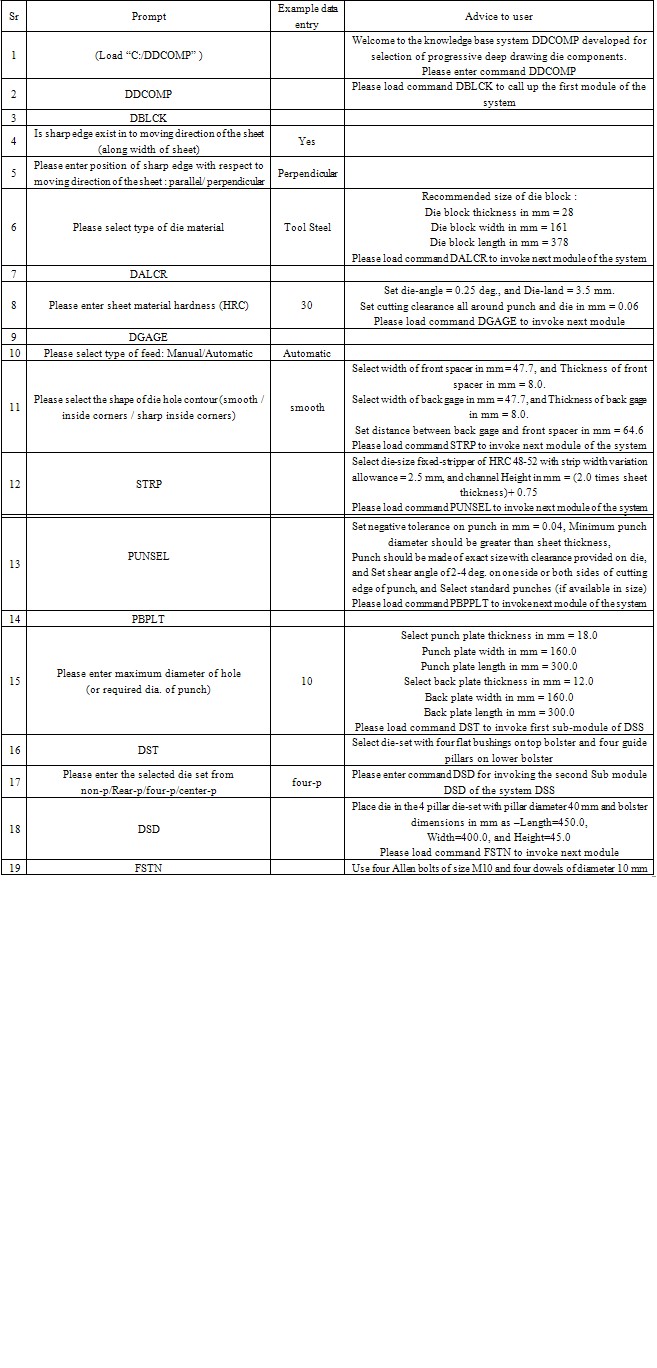
- Development of the proposed system includes various steps[24] such as knowledge acquisition, framing of production rules, verifications of production rules, selection of knowledge representation language, identification of hardware, development of a knowledge base and construction of user interface. Knowledge that goes into the development of the proposed system are essentially collected by on-line and off line consultation with die design experts, design consultants, tool design engineers, shop floor engineers of different stamping industries, referring research articles, catalogs and manuals of various stamping industries[25]. The design information gathered from various sources has been organized into unique hierarchical knowledge base and represented using suitable production rules of the IF-THEN variety. The production rules framed for each module were cross checked from another team of die design experts by presenting them IF-condition of the production rule of IF-THEN variety. A sample of production rules so framed and verified and then incorporated in the modules of the proposed system is given in Table 1. The sequencing of production rules of proposed system is unstructured as this arrangement allows insertion of new production rules even by relatively less trained knowledge engineer. The proposed system is implemented on PC (Pentium 4 CPU, 2.4 GHz, 2GB of ) with Autodesk AutoCAD 2008. The production rules incorporated in all the modules of the proposed KBS have been coded in AutoLISP language. The production rules and the knowledge base of the system are linked together by an inference mechanism, which makes use of forward chaining.The system works with input information supplied by the user coupled with the knowledge stored in the knowledge base, to draw conclusions or recommendations. The proposed system overall comprises of more than 300 production rules of IF-THEN variety. However, the system is flexible enough as its knowledge base can be updated and modified, if necessary, on the advancement in technology and the availability of new facilities on shop floor.
3.2. Execution of the Proposed System
- Execution of the proposed system is shown in Figure 1. Initially user has to enter part details such as sheet thickness, sheet material, etc. through input interface created using Visual Basic 6. The system stores this information automatically in a data file labelled as PART.DAT. This part data file can be used further for execution of other modules of the system. The first module DBLCK of the proposed system invites the user to enter direction of sharp edge of strip along the width through the user interface. The outputs of DBLCK module in form of size of die block are stored automatically in an output data file DBLCK.DAT.This data file can be recalled during the execution of other modules of system. The next module is DALCR has been constructed for assisting the user in selection of proper die-angle, die-land and cutting clearance on die and punch. The intelligent advices imparted by this module are stored in an output data file labelled as DALCR.DAT. The third module labelled as DGAGE is developed for selection of proper size of die gages (front spacer and back gage) and distance between die gages. The recommended dimensions are automatically stored in an output data file DG.DAT. The next module STRP is developed for selection of type of stripper and size of stripper plate. The module is designed to take the dimensions of die block as an input from the data file DBLCK.DAT generated during the execution of previous module developed for selection of die block. The intelligent advices imparted by the module in form of stripper details are stored automatically in another output data file namely STRP.DAT. The module labelled as PUNSEL has been developed to assist the users for selection of type of punch (es) and their dimensions. The output of this module is stored in an output data file namely PUNSEL.DAT file. Another module PBPLT is developed for selection of size of punch plate and back plate. The modules PUNSEL and PBPLT are designed to take size of die block automatically from the data file DBLCK.DAT. The intelligent advices imparted by the module PBPLT in the form of dimensions of back plate and the punch plate are stored in an output data file PBPL.DAT. The next module DSS has been developed for selection of type of die-set and their dimensions. This module comprises of two sub-modules namely DST and DSD developed respectively for the selection of type of die-set and dimensions of die-set. The module is designed to take required inputs from the output data file DBLCK.DAT generated during the execution of previous module. The recommended type of die-set is stored in an output data file namely DST.DAT and the recommended dimensional data namely thickness, width and length of bottom and top bolster of die-set, diameters of guide pillars and guide bushes are stored automatically in an another output data file DSD.DAT. The data stored in these files can be utilized further for modeling of die-set using AutoCAD and AutoLISP routines. The last module labelled as FSTN of the proposed system has been developed for selection of number and size of fasteners (bolts and dowels) required for locating and alignment of plate elements and other components of deep drawing die. The expert advices imparted by this module are stored in an output data file namely FSTN.DAT.
4. Validation of the Proposed System
- The proposed KBS has been tested in many sheet metal industries by taking various types of deep drawn sheet metal parts. Typical prompts, user responses and expert advices obtained during the execution of system for one industrial sheet metal part (Figure 2) are depicted in Table 2. The user interface developed to enter part details is shown in (Figure 3). The outputs of various modules of proposed system in form of selection of dimensions of die block (Figure 4), selection of proper die angle, die land and cutting clearance (Figure 5), selection of dimensions of die gages (Figure 6), selection of stripper and stripper plate (Figure 7), selection of punch details (Figure 8) selection of dimension of punch plate and backup plate (Figure 9), selection of type die sets (Figure 10), selection of die set dimensions of die-set (Figure 11) and selection of fasteners (Figure 12) are found to be reasonable and very similar to those actually used in industry (M/s Shreyash Tools and Components, Pune, India for the example component). Notable features of the proposed system are its parametric approach and low cost of implementation.
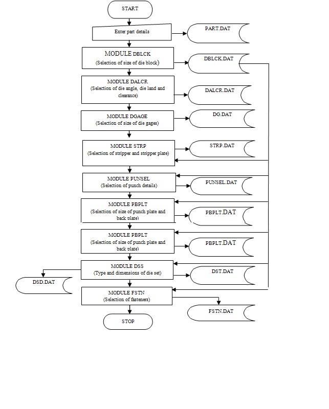 | Figure 1. Execution of proposed KBS |
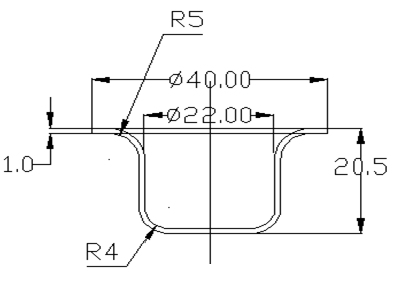 | Figure 2. Example component (All dimensions in mm; Sheet material: M.S, Sheet thickness: 1.0 mm) |
|
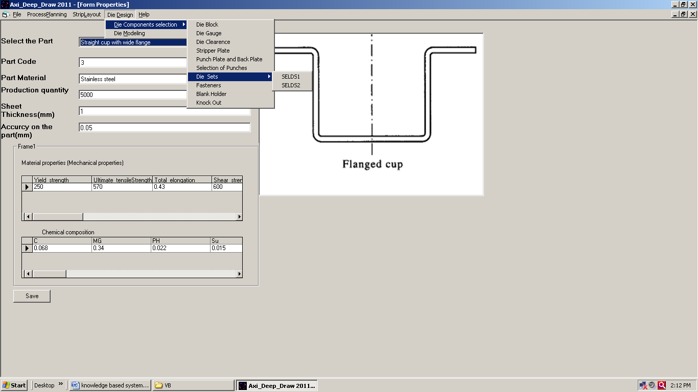 | Figure 3. User interface to input part details |
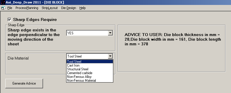 | Figure 4. Output of DBLCK module |
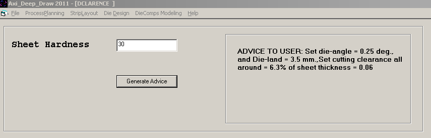 | Figure 5. Output of DALCR module |
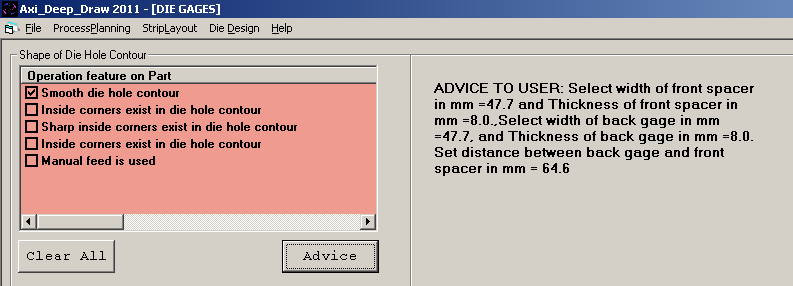 | Figure 6. Output of DGAGE module |
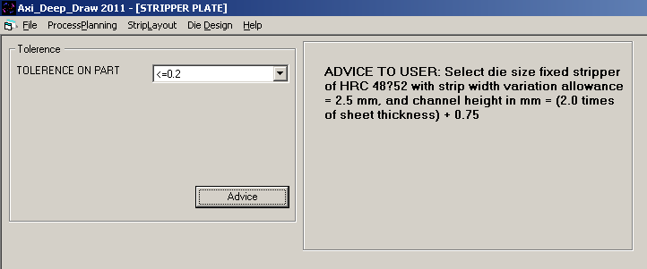 | Figure 7. Output of STRP module |
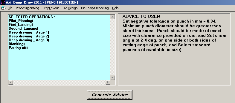 | Figure 8. Output of PUNSEL module |
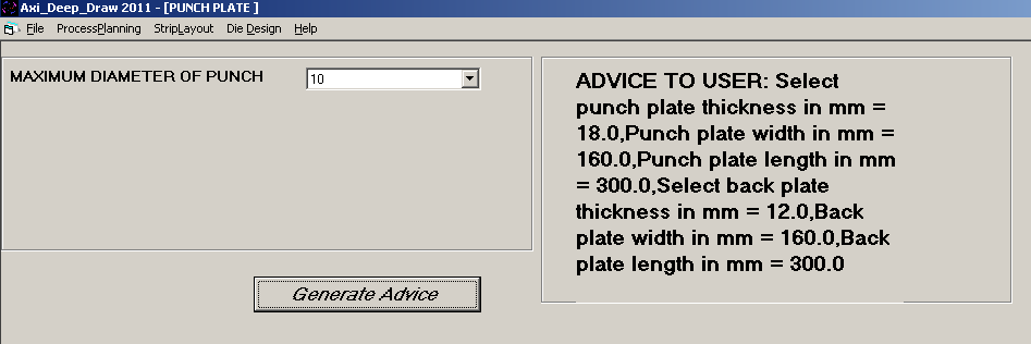 | Figure 9. Output of PBPLT module |
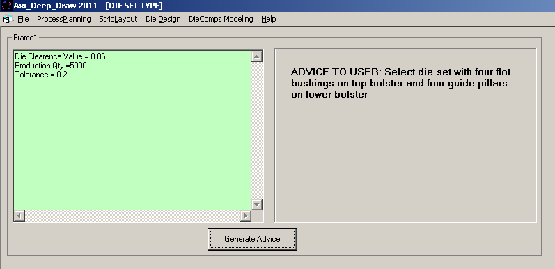 | Figure 10. Output of DST module |
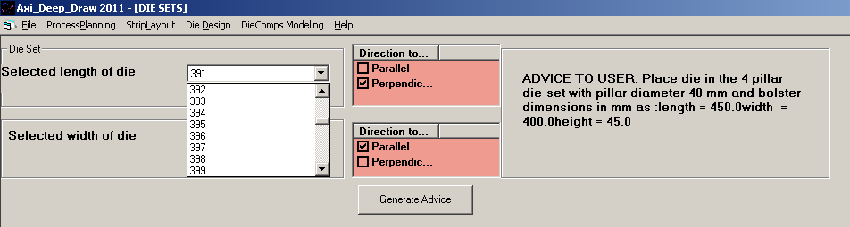 | Figure 11. Output of DSD modules |
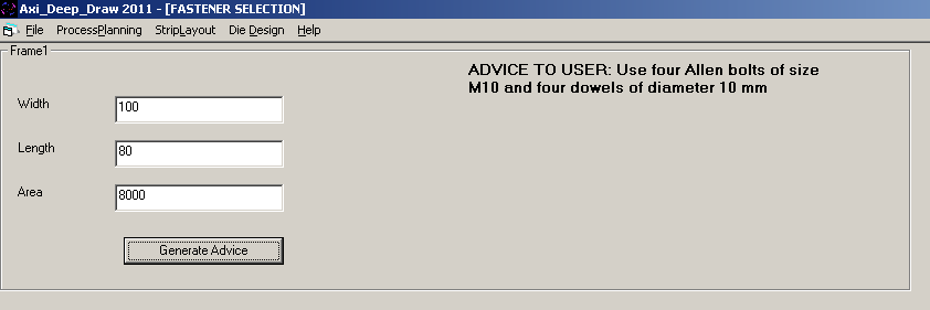 | Figure 12. Output of FSTN module |
5. Conclusions
- In the present research work, a KBS developed for automatic selection of major components of deep drawing die has been presented. The system has been built using production rule based approach of AI. Considerations for selection of die components and procedure used for development of the proposed system have been discussed at some length. The proposed system is capable to assist process planners and die designers of sheet metal industries for design of deep drawing dies. The system has been tested successfully for various types of deep drawn sheet metal parts. The system is coded in AutoLISP and Visual Basic 6 and interfaced with AutoCAD. A parametric approach with low cost of implementation of the proposed system makes it affordable even for small scale stamping industries. Further, knowledge base of the system is flexible enough to accommodate new knowledge or editing of existing knowledge easily due to advancement in sheet metal technology in the future.In the future, research efforts are required for the development of an intelligent CAD system for modeling of die components and die assembly of deep drawing die through integration of the modules of proposed system.
ACKNOWLEDGEMENTS
- Authors would like to express their sincere gratitude to Mr. Ashok Salunkhe, Managing Director in M/s Shreyash Tools and Components, Pune, India and all other domain experts for providing their expertise in the development of proposed knowledge based system.
References
| [1] | W. Singh, and K. Rao, “Knowledge-based process layout system for axisymmetrical deep drawing using decision Tables,” Computers Ind. Engng., vol. 32, pp. 299- 319, 1997. |
| [2] | B. T. Cheok, and K. Y. Foong, “An intelligent planning aid for the design of progressive dies,” Proc. Institution of Mechanical Engineers, Part B: Journal of Engineering Manufacture, vol. 210, pp. 25-35, 1995. |
| [3] | V. Naranje, and S. Kumar, “Design of Deep Drawing Die: An Expert System Approach,” Journal of Manufacturing Engineering, vol. 6, pp. 99-105, 2011. |
| [4] | S. Kumar, and R. Singh, “A knowledge-based system to automate the selection of progressive die components,” Int. J. Computational Materials Science and Surface Engineering, vol. 1, pp. 85 –96, 2007. |
| [5] | S. Kumar, and R. Singh, “An intelligent system for selection of die-set of metal stamping press tool,” Journal of Materials Processing Technology, vol. 164–165, pp. 1395–1401, 2005. |
| [6] | M. Karima, and M. J. Richardson, “A knowledge-based systems framework for computer-aided technologies in metal forming,” Journal of Mechanical Working Technology, vol. 15, pp. 253-273, 1987. |
| [7] | X. Xiao, S. Chen, G. Wang, and J. Xiao, “An expert system for process planning for drawing,” Adv. Tech. Plast. vol. 1, pp. 545–549, 1990. |
| [8] | X. D. Fang, and M. Tolouei-Rad, “Rule-based Deep-Drawing process planning for complex circular shells,” Engng Applic. Artif. Intell., vol. 7, pp. 395-405, 1994. |
| [9] | M. Tisza, “Expert system for metal forming,” Journal of Materials Processing Technology, vol. 53, pp. 423- 432, 1995. |
| [10] | S. Esche, S. Khamitkar, G. Kinzel, and T. Altan, “Process and die design for multi-step forming of round parts from sheet metal,” Journal of Materials Processing Technology, vol. 25, pp. 24-33, 1996. |
| [11] | S. B. Park, Y. Choi, B. M. Kim, and J.C. Choi, “A study on the computer-aided process design system of axisymmetric deep drawing products,” Journal of Materials Processing Technology, vol. 75, pp. 17–26, 1998. |
| [12] | J. C. Choi, C. Kim, Y. Choi, J. H. Kim, and J. H. Park, “An integrated design and CAPP system for deep drawing or blanking products,” Int. J Adv Manuf Technol, vol. 16, pp. 803-813, 2000. |
| [13] | D. H. Park, and K.D.V.Y. Prasad, “Computer aided process planning for non-axisymmetric deep drawing products” in Proc. AIP Conference, vol. 712, 2004, pp. 1985-1990. |
| [14] | T. S. Kim, S. J. Lee, S. K. Lim, and S. S. Lee, “Development of an expert system for the draw die design in automotive industry,” in Proc. Computer Supported Cooperative Work in Design, 2006. CSCWD '06.pp. 1-6, 2006. |
| [15] | B. C. Hwang, S. M. Han, W. B. Bae, and C. Kim, “Development of an automated progressive design system with multiple processes (piercing, bending, and deep drawing) for manufacturing products,” Int. J. Adv. Manuf. Technol., vol. 43, pp. 644–653, 2009. |
| [16] | Y. L. Tsai, C. F. You, J. Y. Lin, and K. Y. Liu, “Knowledge-based engineering for process planning and die design for automotive panels,” Computer-Aided Design & Applications, vol. 7, pp. 75-87, 2010. |
| [17] | D. Potocnik, B. Peasan, J. Balic, and M. Ulbin, “Intelligent system for automatic calculations of stamping parameters,” Adv. in Prod. Engg. & Mgmt., vol., 6, pp. 129- 137, 2011. |
| [18] | V. Boljanovic, Sheet Metal Forming Processes and Die Design, New York: Industrial Press, 2004. |
| [19] | I. Suchy, Die Design Handbook, New York: McGraw-Hill, 2006. |
| [20] | D. A. Smith, Die Design Handbook, 3rd ed., New York: Society of Manufacturing Engineers, 1990. |
| [21] | J. R. Paquin, and R. E. Crowle, Die Design Fundamentals, 2nd ed., New York: Industrial Press, 1987. |
| [22] | D. E. Ostergaard, Advanced Die Making, New York: McGraw-Hill, 1967. |
| [23] | J.A. Waller, Press Ttools and Press Works, 3rd ed. London: Portcullis Press, 1978. |
| [24] | S. Kumar, and R. Singh, “A low cost knowledge base system framework for progressive die design,” Journal of Material Processing Technology, vol. 153-154, pp. 958-964, 2004. |
| [25] | V. Naranje, and S. Kumar, “A knowledge based system for manufacturability assessment of deep drawn sheet metal parts,” Journal of Key Engineering Materials, vol. 473, pp. 749-756, 2011. |