M. Mariappan , T. Ganesan , V. Ramu , M. Iftikhar
Robotics and Biomedical Engineering Research Group, University Malaysia Sabah, Kota Kinabalu, 88400, Malaysia
Correspondence to: M. Mariappan , Robotics and Biomedical Engineering Research Group, University Malaysia Sabah, Kota Kinabalu, 88400, Malaysia.
| Email: |  |
Copyright © 2012 Scientific & Academic Publishing. All Rights Reserved.
Abstract
One of the main and recent problem in developing countries like Malaysia is lack of surgeon or specialists, especially in rural areas. Insufficient specialized surgeons in such regions particularly in the niche of orthopedic, causes more fatalities and loss of limbs due to time and distance constrain in attending the patients. A mobile robotic system known as OTOROB (Orthopedic Robot) is designed and developed to aid surgeons to virtually present at such areas for attending patients in order to make life saving decisions. The developed mobile robotic platform is integrated with a flexible robotic arm vision system to be controlled remotely by the remote surgeon to obtain visual inspection on the patients. Fuzzy logic control is implemented in the control system as Artificial intelligence (AI) to provide safety features for the robotic arm articulation. The safety system of the robotic arm consists of Danger Monitoring System (DMS) and Obstacle Avoidance System (OAS). The experiments conducted on DMS shows that the DMS capable of conveying danger level surrounding the robotic arm to the user through GUI with warning indication and obstacle position. While, OAS developed, responded to the mobile and static obstacle around the robotic arm. The robotic arm is capable of avoiding approaching obstacle autonomously via fuzzy control. The smooth control of robotic arm coupled with safety routines improved the overall articulation of the robotic arm. The safety oriented flexible robotic arm system of OTOROB able to deliver reliable and convenient for both remote doctor and patient in real time emergency circumstances.
Keywords:
Telepresence, Orthopedic Robot, Fuzzy Logic, Danger Monitoring System, Obstacle Avoidance System
Cite this paper:
M. Mariappan , T. Ganesan , V. Ramu , M. Iftikhar , "Safety System for Non-Interventional Flexible Robotic Arm of Orthopedic Robot (OTOROB) Using Fuzzy Control", American Journal of Intelligent Systems, Vol. 1 No. 1, 2011, pp. 22-31. doi: 10.5923/j.ajis.20110101.04.
1. Introduction
Medical robotics refers to robotic systems applied within the domain of health care which evolved from multidisciplinary of science and engineering[1]. According to Kanade et al.[2] and Taylor[3], the term medical robotics has often been construed to refer strictly to surgical procedures, however due to its indefatigability, accuracy, and repeatability, robotic technology is increasingly affecting the entire healthcare sector through advances in surgery, diagnosis, preoperative planning, postoperative evaluation, chronic assistive devices, acute rehabilitation, hospital logistics and scheduling, long-term follow-up and quality control. Medical robotics also extensively improves existing medical procedures to be less invasive and produce fewer side effects that would result in faster recovery times and improved worker productivity, improve risk-benefit, cost-benefit ratios and medical errors[4]. Telemedicine refers to the use of telecommunications technologies in healthcare delivery thatallows physicians to provide medical information and services when distance separates the participants[5,6]. Telemedicine has great potential in increasing rural population’s access to health care, particularly in developing countries[6], since with the use of information technology to deliver health care services and information from one location to another, geographically separated location become easy and effective[7,8]. Telemedicine solves the contradiction between the increasing demands for healthcare and limited hospital resources, and allows patients to be monitored remotely during normal daily life, which will enhance the quality of healthcare services[9]. According to Iftikhar et al.,[10] telerounding is remote visiting of patients by treating physician via a mobile robotic platform, which involves the transmission of audiovisual signals between physician’s location and patient’s room. The InTouch Health Inc. has developed various telemonitoring robots to be deployed in remote hospitals such as Remote Presence-6 (RP6), RP7, RP-Lite Robot, and RP-Vantage[11]. RP6 and the latter version of RP7 are controlled via high-speed Internet from any part on the earth, used by specialists for telerounding in wards and communicate to the medical staffs or patients through interactive audio visual interaction[9]. The major niche in medicine that employs robotics is surgical and interventional robotics. The development of surgical robots is motivated by the desire to enhance the effectiveness of a procedure by coupling information to action in the operating room or interventional suite and transcend human physical limitations in performing surgery and other interventional procedures[1]. The earlier surgical robots were used in neurosurgery and orthopaedic surgery as the anatomic landmarks provided convenient, fixed and accurate points of registration by the computer[12]. The Zeus and da Vinci robots are well known telesurgery robots with master-slave configuration where the surgeon controls the surgery and a set of positioners and camera-control equipment that is mounted on the operating room table[13,14]. The other type health care robot that widely used in medical field is telemonitoring robots. Normally, a telemonitoring robot is controlled by a remote doctor for telerounding in hospitals which employs two ways audio visual communication with patients. This type of robots, for instance Remote Presence-7 (RP7) by Intouch Inc. were successfully used as telehealth system and become a new modality for doctor-patient interactions, particularly in areas where access to medical expertise are limited[15]. Yet, the need for a telepresence medical robotic system to diagnose patients in emergency units at remote areas is still not met. In the case of a developing country like Malaysia, with insufficient healthcare access in remote areas, requires new kind of robotic telepresence system to overcome surgeon or specialist shortage. The increase of road accidents is in link with the rapid growth in population, economic development, industrialisation and motorisation encountered by the country[16]. According to Abdul Rahman et al. [17] injuries due to road traffic accidents is third cause of admission and fifth cause of death in Malaysian government hospitals in 2003, where traffic accidents in Malaysia have been increasing at the average rate of 9.7% per annum. Table 1 presented below reveals road accidents statistic from year 2003 to 2010 released by Road Safety Department, Ministry of Transportation (MOT).| Table 1. Road accidents statistics from year 2003 to 2010 |
| | Year | Total Accidents | Type of injuries | | Death | Critical | Light | | 2003 | 298,653 | 6,286 | 9,040 | 37,415 | | 2004 | 326,814 | 6,228 | 9,229 | 38,631 | | 2005 | 328,268 | 6,188 | 9,397 | 31,429 | | 2006 | 341,232 | 6,287 | 9,254 | 19,884 | | 2007 | 363,319 | 6,282 | 9,273 | 18,444 | | 2008 | 373,047 | 6,527 | 8,866 | 16,901 | | 2009 | 397,330 | 6,745 | 8,849 | 15,823 | | 2010 | 414,421 | 6,872 | 7,781 | 13,616 | | Source: Road Safety Department, Malaysian Ministry of Transportation |
|
|
Studies also revealed that number of fatalities (death within 30 days after accident) also increased due to serious injuries[16]. Measures taken to deliver efficient treatment and healthcare services to victims particularly in remote or rural areas is not fully met. According to Vilchis et al.[18] specialized physicians are lacking in some healthcare centres or in emergency situations. Those who live in rural or underdeveloped areas are likely to have more limited access to high-quality healthcare, since new state-of-the-art procedures can even be difficult to obtain in large metropolitan areas[13]. In developing countries like Malaysia, shortages of specialist or surgeon in remote or rural areas demand for new kind of telemedicine system that enables the specialist to be present virtually[19]. Most of the emergency cases reported results in loss of limbs due to excessive loss of blood due to injuries or sometimes even deaths. Currently available telemonitoring robots such as RP7 is used for telerounding purpose rather than attending patients in emergency situations. Most of the recently developed telemedicine robotic systems being used are for operation procedures and also for post operation or diagnosis procedures for patient recovery[20]. A robotic system with flexible vision system for inspection and medical instruments to obtain vital signs of the patient is more promising to attend patients in such situations. A mobile robotic platform known as OTOROB (Orthopaedic Robot) is developed in order to assist medical personals in rural or remote areas to deliver sufficient healthcare services in emergency circumstances. The development of OTOROB is focused in medical discipline of orthopedic, since most of the accidents cases reported and admitted is due to broken limb bones with neurosurgical complications. Normally, while attending accident cases, pre-hospital teams provide on-scene initial assessment and resuscitation and transmit this information to a physician, mainly through voice communication. Therefore, the physician can only make an assessment based on what is described and cannot continuously monitor an injured victim through visual communication (e.g., video)[21]. 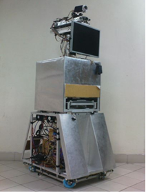 | Figure 1. Orthopedic Robot (OTOROB) mobile robotic platform. |
OTOROB is a mobile robotic platform with onboard medical instruments, X-ray illuminator and scanner module and a flexible robotic arm which is controlled via Internet by orthopedic surgeon from distance. The OTOROB system possesses two way audio visual communication systems, which communicates with medical personals at remote hospital and surgeon from distance at real time. The robotic platform enables virtually present doctor to conduct visual inspection (video), diagnose and rectify the type of injury, and receive victim’s vital signs, thus enables the surgeon to decide on further medical procedures. The Figure 1 shows mobile robotic platform, OTOROB developed for this particular purpose.
2. Flexible Robotic Arm Architecture
The robotic arm serves as the key component of OTOROB to act as virtually present doctor’s ‘eyes’ in emergency situations to diagnose the patient. Mostly available telemonitoring medicals robots equipped with static cameras which restricted visual projections to only at certain projection angle. A flexible robotic arm is proposed and designed to be installed at the upper part of OTOROB which acts as a “head”. Due to safety features, the flexible robotic arm is designed with extending and retracting capabilities which gives a telescopic motion. The telescopic motion is important in order to provide sufficient stroke for maximum reach and at the same time retract safely to the original position which enclosed by OTOROB body dimension.A high resolution CCD video camera with 22x optical zoom feature is required as the end of the robotic arm as end effector to acquire maximum visual coverage. The camera is supported by two servos which delivers 180˚ of yaw and pitch motion to the camera. The robotic arm can be rotated in y-axis 180˚. The combination of mechanical robotic arm features and video camera (with zoom feature) as end effector provides maximum visual coverage which covers more than 80 percent of the standard hospital bed area. Figure 2 shows the flexible robotic arm assembly on the mobile robotic platform.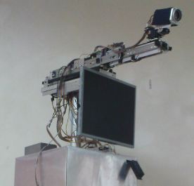 | Figure 2. Flexible robotic arm assembly on mobile robotic platform. |
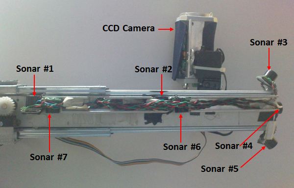 | Figure 3. Sonar integration on the robotic arm mechanical design. |
The telescopic robotic arm design ensures safe and stable navigation for OTOROB since projection of any robotic part beyond the robots dimension result imbalance in center of gravity which eventually influences the stability of robot. Furthermore, during navigation robotic parts that protrude beyond robot’s dimension cause possible threats or injuries to nearby human and also can cause damage to the robot itself in case of collision with other static or moving objects. At the same time, the articulation of the robotic arm must provide sufficient freedom and coverage to obtain clearer vision of the patient.Other than the mechanical design, ultrasonic range finder sonars are integrated in the robotic arm design to enhance the safety features. These sensors are primarily employed in danger monitoring and obstacle avoidance schemes. The integration of the sonars in the robotic arm is as in Figure 3.
3. Safety System of Robotic Arm
Safety is an important consideration in installing, programming, operating and maintaining robotic system. Safety is also considered as a judgment of the acceptability of danger, where danger is the combination of hazard and risk. Safety is very important in medical robots and must be addressed at all phases of design, manufacture, and application[22]. While, according to Tavakoli et al.[23], safety is a main concern for visual feedback surgery to the surgeon by incorporating safety measures into the system. Safety system control algorithm is developed and incorporated in flexible robotic arm control system, since OTOROB is designed as ‘front line medical support system’ to diagnose patient with orthopedic complications in emergency circumstances. The safety control of flexible robotic arm ensures safe and reliable articulation of the flexible robotic arm to avoid contact or collision with any objects or human nearby which can cause possible injuries. In some case any part of the robot that can come into contact with the patient may contaminate the surgical field which is potentially dangerous[22]. A fuzzy logic control system is introduced to enhance the safety system control algorithm of the flexible robotic arm since fuzzy control provides smooth and non-linear control.
3.1. Fuzzy Logic
The concept of Fuzzy Logic (FL) was proposed by Lotfi Zadeh, presented as a way of processing data by allowing partial set membership rather than crisp set membership or non-membership in order to mimic human decision making capability. The effectiveness using FL increase since feedback controllers can be programmed to accept noisy or imprecise input. A FL model with its fundamental input-output relationship consists of four components namely, fuzzification, fuzzy inference engine, defuzzification and a fuzzy rule base. The FL model is as shown in the Figure 4.In fuzzification step, crisp inputs are fuzzified into linguistic values to be associated to the input linguistic variables. After fuzzification, the inference engine refers to the fuzzy rule base containing fuzzy IF-THEN rules to derive the linguistic values for the intermediate and output linguistic variables. Once the output linguistic values are available, defuzzification produces the final crisp values from the output linguistic values.The FL model is adapted in the flexible robotic arm to provide intelligent control in Danger Monitoring System (DMS) and Obstacle Avoidance System (OAS). The FL model for flexible robotic arm safety system is developed by using Matlab Fuzzy Logic Toolbox software. Then, the FL control is converted into C codes for embedded application for simplicity and control performance. 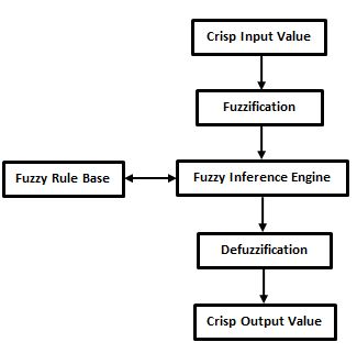 | Figure 4. Fuzzy logic execution model |
4. Danger Monitoring System (DMS)
Danger monitoring involves the use of sensors and other feedback devices to indicate conditions or events that are unsafe or potentially unsafe. Often, danger monitoring system is employed to protect humans within the working envelope of the robot and robotic parts. Sensors are used to scan for obstacles that intrude the working envelope and other deviations from the normal operating conditions. While, feedback devices such as encoders are used to monitor the displacement of robotic parts relative to the original position. Great care must be taken to anticipate all possible mishaps that might occur during robotic operation and a workable system is essential to safeguard and prevent the damage resulting from these mishaps. The Danger Monitoring System (DMS) is employed in flexible robotic arm to determine intrusion of obstacle in Obstacle Avoidance System (OAS).A novel fuzzy logic based Danger Monitoring System (DMS) is designed and implemented in flexible robotic arm control architecture to monitor all possible mishaps that might occur during robotic control. The system basically provides the location of obstacle and the overall danger level by using fuzzy inference engine. The flow control of DMS is as presented in Figure 5.The ultrasonic range finder sensor array constantly scans for detection of obstacles within the specified range. The detection of the possible obstacles is divided into three regions for every sensor units. The regions are, namely; Green Zone ranges from 50cm and above, Yellow Zone ranges from 50-25cm and Red Zone ranges from 25-0cm. Figure 6 illustrates the specified regions from top view.Through the microcontroller built in ADC function, the analogue signal of the ultrasonic range finder is converted into linear distance. The position of the obstacle is mapped into specified detection range relative to the obstacle distance. The obstacle position data is fed into fuzzy engine for fuzzification. The crisp inputs are given linguistic variables Close, Medium and Far. The obstacle distance from robotic arm associates with the fuzzy crisp input is as in Table 2. 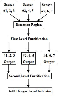 | Figure 5. Danger Monitoring System (DMS) control flow. |
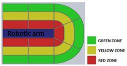 | Figure 6. Obstacle detection region. |
| Table 2. Obstacle distance and associated crisp input |
| | Crisp Input | Distance (cm) from robotic arm | | Close | 0-25 | | Medium | 25-50 | | Far | >50 |
|
|
Set of fuzzy rules are applied with AND logic operator in Sugeno method with weighted average defuzzification. During the first level fuzzification, the fuzzy inputs from the sensors are divided into left coverage area, front coverage area and right coverage area. Each of the coverage area carries different number of sensor input depending on the arm stroke length. The fuzzy inference system is employed separately for each coverage area. After defuzzification, each coverage area output carries different weight depending on the number of sensors involved. The fuzzy crisp inputs for each sensors are; Close(1), Medium(1), and Far(1), where (1) indicates first level fuzzy inference. The rule table of first level fuzzy engine inference system for left coverage area (sensor #3 and sensor #4, where arm stroke is 0-10cm) is as in Table 3.| Table 3. First level fuzzification for left coverage area (sensor #3 and sensor #4) |
| | | Close(1) | Medium(1) | Far(1) | | Close(1) | Close | Close | Close | | Medium(1) | Close | Medium | Medium | | Far(1) | Close | Medium | Far |
|
|
The output of first fuzzy engine is fed as the input in second level fuzzification. Finally, in the defuzzification step, the sensor input data from each coverage area is weighed collectively according to the number of inputs associated since number of sensors involved in the detection differs relative to the robotic arm stroke. The availability of the sensors relative to the stroke length is as presented in the Figure 7.The crisp outputs of the second level fuzzy inference system are danger level indicator with variable colour codes associated with the different danger levels, which are; Green (Very Safe), Light Green (Safe), Yellow (Moderate Safe), Orange (Dangerous) and Red (Very Dangerous). The fuzzy logic rule table for DMS (involving left coverage area and front coverage area) is as shown in Table 4. | Figure 7. Sensor availability associated to the robotic arm stroke length. |
| Table 4. Fuzzy logic rule table for DMS |
| | | Close | Medium | Far | | Close | V.Dangerous | Dangerous | Dangerous | | Medium | Dangerous | M.Safe | Safe | | Far | Dangerous | Safe | V.Safe |
|
|
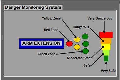 | Figure 8. Danger Monitoring System panel. |
The fuzzy logic inference system is implemented in microcontroller using C codes. The output crisp value is sent from the Master PIC to the host computer via USB which is then processed by the GUI to be displayed as the danger level in series of colour codes which associates with the fuzzy crisp output. The GUI also displays the position of the obstacle relative to the robotic arm in series of coloured zones (green, yellow and red). The Danger Monitoring System panel located in the GUI is presented in the Figure 8.
5. Obstacle Avoidance System (OAS)
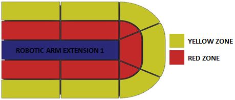
Obstacle avoidance in robots is accomplished through successful navigation through various physical distortion which achieved by integration of various sensors. Normally, intelligent agent such as fuzzy logic and neural network scheme is employed to accomplish these tasks. Obstacle avoidance system is common in autonomous and manual mobile robots for the navigation purpose to avoid collision while in motion. In medical robotics such system is implemented widely in surgical robots due safety issues since involving intervention with human subjects. Li et al.[24] presented an online collision avoidance method for real time interactive control of surgical robot for sinus cavity surgery where the inserted tools avoid collisions or excessive force on delicate anatomy, while still performing the desired motion to accomplish the intended task. The sensor network incorporated normally gain feedback in order to predetermine the possible obstacle position, orientation and path. The OAS of flexible robotic arm incorporates fuzzy logic with ultrasonic range finder sensor network to aid in obstacle detection and avoidance. The OAS is extension of DMS, where OAS executes autonomous control to the flexible robotic arm while the OAS monitors all possible intrusion. The OAS execution range is in Red Zone, where the detection range is from 0 to 25cm. The Red Zone for OAS execution is as shown in Figure 9. 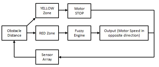 | Figure 9. Danger Monitoring System detection region. |
 | Figure 10. Fuzzy Logic model of Danger Monitoring System. |
The FL controlled OAS overwrites the user controlled flexible robotic arm articulation in the presence of obstacle in Red zone. The fuzzy crisp output differs for both Yellow Zone and Red Zone. The fuzzy logic model for flexible robotic arm OAS is as illustrated in the Figure 10.The sensor array feedback provides the current distance of the obstacle from the robotic arm, which is identified as static and mobile obstacle. Mobile obstacles possess greater threat to the safety issue rather than static obstacle. Detection of obstacle in Yellow Zone immediately stops the motor activity by overriding the user control articulation regardless of the status of the obstacle as static or mobile. Unlike static obstacle which can be easily tackled by detection at yellow zone, mobile obstacles that moves on a path of collision with the robotic arm which can be potentially hazardous. In the presence of mobile obstacle, the robotic arm tends to actuate in the same direction as the obstacle with varying speed to maximize the distance between obstacle and robotic arm until a safe distance is achieved. Through this intelligent autonomous manure, the risk of colliding with nearby objects is reduced, at the same time simplifies the articulation control for the remote doctor or surgeon. The obstacle distance input is given linguistic variables Far, Medium and Near ranging from 5-25cm. While, the obstacle speed input is given linguistic variables Fast, Moderate and Slow. The output crisp is the motor speed (%) with linguistic variables of High Speed (HS), Medium Speed (MS) and Low Speed (LS). The fuzzy rule table for the OAS is as given in Table 5.| Table 5. Obstacle Avoidance System fuzzy logic rule table |
| | | Near | Medium | Far | | Slow | MS | LS | LS | | Moderate | HS | MS | LS | | Fast | HS | HS | MS |
|
|
The fuzzy rules table presented above is applied in the fuzzy IF-THEN inference engine prior to defuzzification. After defuzzification, crisp output value for motor speed (%) is generated. The generated input speed (%) is correlated with PWM output to regulate the final speed of the motor to avoid approaching obstacle. The OAS data modelling is done by using Matlab ANFIS Editor. The modeled and simulated fuzzy logic inference system is converted into embedded control and rewritten in C codes for simplicity and portability.
5.1. DMS for Obstacle Avoidance
The fuzzy control algorithm is implemented in microcontroller and software interface (GUI) and tested in real time. Tagaki-Sugeno method is used to develop the fuzzy logic model with weighted average defuzzification technique. FIS Editor of Fuzzy Logic Toolbox is used to generate OAS rule diagram and 3D surface plot. The weighted average calculation used in the fuzzy model is presented in equation (1). | (1) |
During the danger monitoring test an obstacle is introduced at the left end corner, about 40cm from the robotic arm. The fuzzy execution during extension length of 25cm is discussed in following parts. The discussion focuses on danger monitoring for approaching obstacle from left side, right side and front side of the robotic arm and the GUI warning indication associated to the detection range. The active sensor monitoring region at stroke length of 25cm is as presented in Figure 11.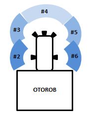 | Figure 11. Active sensor monitoring at robotic arm stroke of 25cm. |
The three different first level fuzzy engines fuzzify the sensor inputs; where initially involves sensor#2 and sensor#3, secondly sensor#3, #4 and #5 and lastly sensor#5 and sensor#. The rule viewer for the first level fuzzification is as in Figure 12.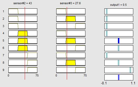 | Figure 12. Rule viewer of first level DMS fuzzification. |
The rule viewer shows the position of obstacle detection by sensor#2 at 43.0cm and sensor#3 at 27.6cm. The crisp output for this corresponding obstacle ranges is ‘Medium’. The output crisp for ‘Close’ is 0, ‘Medium’ is 0.5 and ‘Far’ is given 1. The crisp output of the defuzzification is mapped in surface plot corresponding to the detection range as in Figure 13.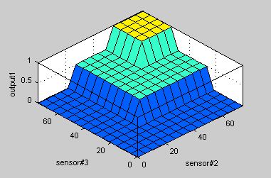 | Figure 13. Surface plot of the first level DMS defuzzification |
Upon the completion of the first defuzzification, the output from left side (sensor#2 and sensor#3), front side (sensor#3, #4, and #5) and right side (sensor#5 and sensor#6) are used as the input for the second level fuzzification. The second level fuzzification involving inputs from left and front side sensors is presented in the rule viewer in Figure 14.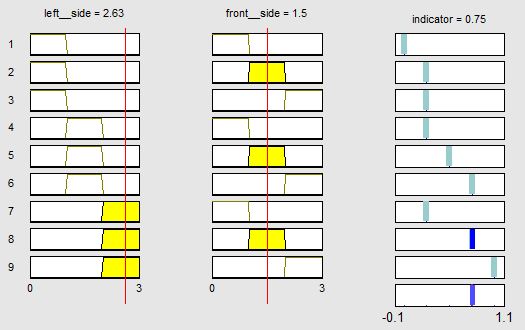 | Figure 14. Second level DMS fuzzification rule viewer. |
The crisp outputs for the second level fuzzification are ‘V.Dangerous’ = 0, ‘Dangerous’ = 0.25, ‘M.Safe’ = 0.5, ‘Safe’ = 0.75 and ‘V.Safe’ = 1. The rule viewer above shows the left fuzzy input ‘Far’ while front fuzzy input ‘Medium’. The defuzzification output for these combinations is ‘Safe’ which is denoted by the constant 0.75. The surface plot for the second level defuzzification is as presented in the Figure 15.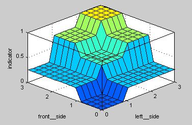 | Figure 15. Second level DMS fuzzification surface plot. |
The corresponding ‘Safe’ output is send to the GUI as variable through USB and the GUI displays the current danger state. The screenshot of the danger monitoring panel during the test is as shown in Figure 16.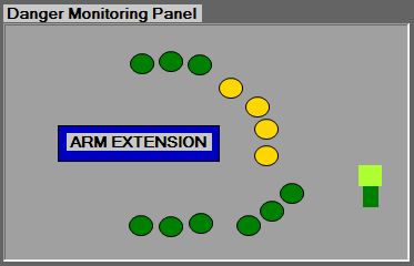 | Figure 16. Danger monitoring control panel of the GUI. |
The detection of the subjected obstacle is detected and indicated as in yellow region. While, sensor#1 and sensor#7 do not indicate any detection since the extension tested is at 25cm. The overall danger level surrounding the robotic arm is displayed as two bars (green and lime green) which indicate the ‘Safe’ state. The DMS for obstacle avoidance is further tested with different robotic arm extension length, obstacle orientation and number of obstacles. The danger monitoring panel displayed satisfactory detection and danger indicator corresponding to the test performed.
5.2. Execution of Obstacle Avoidance System (OAS)
The execution of OAS is based on the detection region of the obstacle and speed of the obstacle. Fuzzy logic is applied in OAS of motile obstacles, while OAS for obstacle detection is executed by conventional microcontroller routine. Any detection of obstacle in the Yellow region immediately prohibits the actuation of the robotic arm through motor towards the obstacle path. A set of tests are conducted in order to determine the execution of OAS at different position around the robotic arm. The obstacles are introduced at distance of 40-50cm away from the robotic arm where the Yellow region lies between 25cm-50cm range of detection. Later the robotic arm is articulated towards the subjected obstacle. The Figure 17 shows the control freedom and control restriction corresponding to the obstacle subjected. 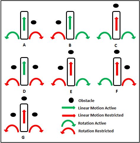 | Figure 17. Control freedom of robotic arm in the presence of obstacle. |
The above Figure shows that the robotic arm corresponded to the subjected obstacle by restricting the articulation towards the detected obstacle. While, other possible controls which are not affected by the obstacle is kept active. This safety feature avoids collision between objects or humans and robotic arm by autonomously blocking active user control. This feature can reduce the human error and improve the safety. The fuzzy rule set is modeled by implementing Tagaki-Sugeno method using Matlab Fuzzy Logic Toolbox in OAS of motile obstacle. FIS Editor of Fuzzy Logic Toolbox is used to generate OAS rule diagram and 3D surface plot. Fuzzy logic is applied in OAS of motile obstacles primarily to respond against approaching obstacle with different speed. The fuzzy control is aimed to deliver suitable speed to the motor to articulate the robotic arm autonomously against the approaching obstacle relative to the obstacle speed. The execution of the OAS fuzzy engine is based on the obstacle speed and obstacle distance from the robotic arm. Both these parameters are used as the fuzzy crisp input during fuzzification. The crisp output is the motor speed which is controlled by the PWM. The output motor speed of the fuzzy is quoted in percentage with reference to the current available maximum voltage. The fuzzy rule set of OAS for linear motion as presented in Figure 18.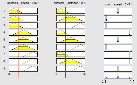 | Figure 18. Fuzzy rule set of OAS for linear movement. |
The fuzzy rule viewer shows the obstacle speed as 0.98cms-1 and obstacle distance from the robotic arm lies in the ‘Near’ region about 9.7cm and the associated motor output speed at 65%. The obstacle speed, obstacle distance and motor output speed is correlated and plotted in 3D surface plot as in Figure 19.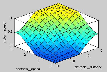 | Figure 19. Surface plot of flexible robotic arm OAS for linear movement. |
The modeled fuzzy logic inference scheme is converted into C codes for embedded application using PIC18F4550. Experiments are conducted using external mobile obstacle with various speed to evaluate the modeled fuzzy system. A linear rail unit is integrated with a DC motor and a circular bar is placed vertically at the end point of the rail used as the test kit for the experiments conducted. The DC motor is used to actuate the rail forth and back at various speeds. First series of experiments tested the response of the fuzzy control towards approaching obstacles without considering the speed of the motor. Early observations proved that the robotic arm fuzzy controlled OAS executed properly and effectively based on the autonomous movement of the robotic arm. The Figure 20 shows the robotic arm autonomous movement when subjected to moving obstacle.In the figure above the green arrows indicate the autonomous articulation of the robotic arm direction responding to the approaching obstacle. The experimental control proves that fuzzy logic control overrides the remote user articulation in the presence of obstacle. The robotic arm tends to move away from the approaching obstacle in order to maintain a safe distance from obstacle where the auto articulation ensures the obstacle is free from the Red zone. The fuzzy controlled autonomous articulation also exhibits smoother movements compared to conventional algorithm.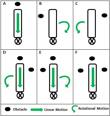 | Figure 20. Obstacle avoidance pattern of flexible robotic arm according to obstacle detection at various positions. |
The second series of experiment is carried out with the same type of obstacle, with varying speed approaching the robotic arm. The speed of the moving obstacle is predetermined and regulated and the robotic arm movement speed is measured. Both rotational and linear movement of the robotic arm is measured. The maximum speed of the mobile obstacle is set at 2.5cms-1. A video camera is used to record the experiment from top view, which is later analyzed to obtain the accurate timing of the movement. The robotic arm linear and rotational movement speeds obtained is then compared with the motor output speed generated by the fuzzy model discussed earlier.The robotic arm fuzzy controlled obstacle avoidance is tested with eight different speeds. Both linear motion and rotational motion is tested and the motor response speed is tabulated in Table 6.| Table 6: Angular velocity and linear velocity subjected to different obstacle speed |
| | Obstacle Speed (cm/s) | 0.5 | 0.75 | 1.0 | 1.5 | 1.75 | 2.0 | 2.5 | | Angular Speed (cm/s) | 0.43 | 0.71 | 0.92 | 1.52 | 1.81 | 2.08 | 2.45 |
|
|
The data obtained above is converted to speed percentage of motor over average speed of 2.5cms-1 obtained in previous linear and rotational displacement analysis. The average motor speed against subjected obstacle is as presented in Figure 21.The motor speed data obtained proves that the fuzzy implementation produce similar motor speed pattern with the fuzzy output modeled. However, both rotational and linear movement exhibit slight changes in the real time testing. The slight deviation observed is expected due to difference in battery voltage and stress-strain distribution on the robotic arm assembly. 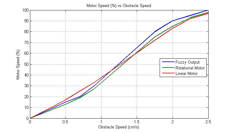 | Figure 21. Average motor speed against subjected obstacle speed. |
6. Conclusions
A mobile robotic system for orthopaedic related injuries known as OTOROB is developed to serve in rural areas which enables the surgeon from different place to virtually present in rural areas. The flexible robotic arm with vision system plays important role in visual inspection of the patient, where high concern is given on the safer articulation of the robotic arm. The safety system of the robotic arm is enhanced by fuzzy logic implementation through Danger Monitoring System (DMS) and Obstacle Avoidance System (OAS). The movement of robotic arm in presence of obstacles is studied and evaluated. The integration of DMS in GUI provides autonomous warning and danger level indicator to the user. While, in the case of obstacle avoidance, the robotic arm is able to avoid safely approaching obstacle autonomously. Thus, the integration of the flexible robotic arm in OTOROB can improve ‘front line’ healthcare services in real emergency circumstances.
ACKNOWLEDGEMENTS
The authors would like to thank the Ministry of Science, Technology and Innovation, Malaysia for their research grant FRGS0177-SP-2009 and FRGS0224-TK-1/2010.
References
| [1] | Yulun Wang, Steven E. Butner, and Ara Darzi. 2006. The Developing Market for Medical Robotics. Proceedings of the IEEE. 94 (9): 1763-1771 |
| [2] | Takeo Kanade, Brian Davies, Cameron N. Riviere. 2006. Special Issue on Medical Robotics. Proceedings of IEEE. 94 (9): 1649-1651 |
| [3] | Russell H. Taylor. 2006. A Perspective on Medical Robotics. Proceedings of the IEEE. 94 (9): 1652-1664 |
| [4] | Allison M. Okamura, Maja J. Matatri_C, and Henrik I. hristensen. 2010. Medical and health-care robotics Achievements and Opportunities. IEEE Robotics & Automation Magazine. (26-37) |
| [5] | Peter Meso, Victor W. A. Mbarika and Sanjay Prakash Sood. 2009. An Overview of Potential Factors for Effective Telemedicine Transfer to Sub-Saharan Africa. IEEE Transactions on Information Technology in Biomedicine. 13 (5): 734-739 |
| [6] | Yajiong Xue and Huigang Liang. 2007. Analysis of Telemedicine Diffusion: The Case of China. IEEE Transactions on Information Technology in Biomedicine. 11 (2): 231-233 |
| [7] | David L. Paul, Keri E. Pearlson and Reuben R. McDaniel, Jr. 1999. Assessing Technological Barriers to Telemedicine: Technology-Management Implications. IEEE Transactions on Engineering Management. 46 (3): 279-288 |
| [8] | J. B. Petelin, M. E. Nelson, J. Goodman. 2006. Deployment and early experience with remote-presence patient care in a community hospital. Surgical Endoscopy. 21 (1): 53-56 |
| [9] | Michelle J Johnson, Xin Feng, Laura M Johnson and Jack M Winters.2007. Potential of a suite of robot/computer-assisted motivating systems for personalized, home based, stroke rehabilitation. Journal of Neuroengineering and Rehabilitation. 4 (6): 6 |
| [10] | M. Iftikhar, M. J. Majid , M. Muralindran, G. Thayabaren , R. Vigneswaran, T.T.K Brendan. 2001. OTOROB: Robot for Orthopaedic Surgeon Roboscope: Non-interventional Medical Robot for Telerounding. 5th International Conference of Bioinformatics and Biomedical Engineering, (iCBBE) 2011. 10-12 May 2011. Wuhan, China. 1-5 |
| [11] | http://www.intouchhealth.com/products.html |
| [12] | Hong Gee Sim , Sidney Kam Hung Yip, Christopher Wai Sam Cheng. 2006. Equipment and technology in surgical robotics. World Journal of Urology. 24 (2): 128-135 |
| [13] | Steven E. Butner and Moji Ghodoussi. 2003. Transforming a Surgical Robot for Human Telesurgery. IEEE Transactions on Robotics and Automation. 19 (5): 818-824 |
| [14] | Mamoru Mitsuishi, Naohiko Sugita, and Phongsaen Pitakwatchara. 2007. Force-Feedback Augmentation Modes in the Laparoscopic Minimally Invasive Telesurgical System. IEEE/ASME Transactions on Mechatronics. 12 (4): 447-454 |
| [15] | Christoph Bartneck, Timo Bleeker, Jeroen Bun, Pepijn Fens, Lynyrd Riet. 2010. The influence of robot anthropomorphism on the feelings of embarrassment when interacting with robots. PALADYN Journal of Behavioral Robotics. 1 (2): 109-115 |
| [16] | Mohamad Nizam Mustafa. 2005. Overview of Current Road Safety Situation in Malaysia. Highway Planning Unit. Road Safety Section, Malaysia Ministry of Works |
| [17] | Hejar Abdul Rahman, Nor Afiah Mohd Zulkifli, Kulanthayan Subramaniam and Law Teik Hua. 2005. Car Occupants Accidents and Injuries Among Adolescents in A State in Malaysia. Proceedings of the Eastern Asia Society for Transportation Studies. 5: 1867–1874 |
| [18] | Adriana Vilchis, Jocelyne Troccaz, Philippe Cinquin, Kohji Masuda, and Franck Pellissier. 2003. A New Robot Architecture for Tele-Echography. IEEE Transactions on Robotics and Automation. 19 (5): 922-926 |
| [19] | M. Muralindran, R. Nagarajan, and K. H. Goh. 2007. AI Application for the PALMBOT Patient Position Tracking System. Malaysia- Japan International Symposium on Advance Technology 2007 (MJISAT),Kuala Lumpur, Malaysia, 12-15 November |
| [20] | Muralindran Mariappan, Thayabaren Ganesan, Muhammad Iftikhar, Vigneswaran Ramu, Brendan Khoo. 2010. A design methodology of a flexible robotic arm vision system for OTOROB. 2nd International conference on Mechanical and Electrical Technology (ICMET). Singapore. Sept 10-12. 161-164 |
| [21] | Lu Qiao and Polychronis Koutsakis. 2011. Adaptive Bandwidth Reservation and Scheduling for Efficient Wireless Telemedicine Traffic Transmission. IEEE Transactions on Vehicular Technology. 60 (2): 632-643 |
| [22] | Russell H. Taylor and Dan Stoianovici. 2003. Medical Robotics in Computer-Integrated Surgery. IEEE Transactions on Robotics and Automation. 19 (5): 765-781 |
| [23] | Mahdi Tavakoli, Arash Aziminejad, Rajni V. Patel, and Mehrdad Moallem. 2007. High-Fidelity Bilateral Teleoperation Systems and the Effect of Multimodal Haptics. IEEE Transactions on System, Man and Cybernetics-Part B: Cybernetics. 37 (6): 1512-1528 |
| [24] | Ming Li, Masaru Ishii, and Russell H. Taylor. 2007. Spatial Motion Constraints Using Virtual Fixtures Generated by Anatomy. IEEE Transactions on Robotics. 23 (1): 4-19 |
 Abstract
 Reference
 Full-Text PDF
 Full-Text HTML