-
Paper Information
- Next Paper
- Paper Submission
-
Journal Information
- About This Journal
- Editorial Board
- Current Issue
- Archive
- Author Guidelines
- Contact Us
American Journal of Geographic Information System
p-ISSN: 2163-1131 e-ISSN: 2163-114X
2019; 8(5): 199-205
doi:10.5923/j.ajgis.20190805.01

Study the Effect of Surrounding Surface Material Types on the Multipath of GPS Signal and Its Impact on the Accuracy of Positioning Determination
 Abstract
 Reference
 Full-Text PDF
 Full-text HTML
Ahmed S. Mohamed1, Mohamed I. Doma2, Mostafa M. Rabah3
1Higher Technological Institute 10th of Ramadan City, 10th of Ramadan City, Egypt
2Faculty of Engineering, Menoufia University, Egypt
3Benha Faculty of Engineering, Benha University, Egypt
Correspondence to: Ahmed S. Mohamed, Higher Technological Institute 10th of Ramadan City, 10th of Ramadan City, Egypt.
| Email: |  |
Copyright © 2019 The Author(s). Published by Scientific & Academic Publishing.
This work is licensed under the Creative Commons Attribution International License (CC BY).
http://creativecommons.org/licenses/by/4.0/

Global Positioning System (GPS) results are suffering from one of the major errors in high precision GPS positioning, the ones caused by reflections, known as Multipath error. Here, we study some of the multipath factors affecting on the accuracy observables obtained from GPS measurements. This will be achieved through monitoring and record the multipath effect according to different types of surface which reflected the signals specific set of generating and monitoring systems for multipath signal is established and a series of controlled experiments are carried out. Experimental results show that Aluminium caused the highest amount of multipath. This is followed by Glass and Wood.
Keywords: GPS, Multipath, Material type Effect
Cite this paper: Ahmed S. Mohamed, Mohamed I. Doma, Mostafa M. Rabah, Study the Effect of Surrounding Surface Material Types on the Multipath of GPS Signal and Its Impact on the Accuracy of Positioning Determination, American Journal of Geographic Information System, Vol. 8 No. 5, 2019, pp. 199-205. doi: 10.5923/j.ajgis.20190805.01.
Article Outline
1. Introduction
- With the sophisticated Global Navigation Satellite System (GNSS), the static and kinematic deformations of the largescale structures can be monitored in the real-time mode with three-dimensional positioning precision to several millimetres. The applications include bridge, dam, pipeline and machinery alignment monitoring. In such scenarios, it is advantageous if the coordinates of target points can be provided with high data rates and high accuracy. The global positioning system (GPS) is an attractive system for providing such data since it is weather independent, has high precision positioning and short observation time, is capable of autonomous operation and does not require a line of sight (LOS) between target point (Elsobeiey and El-Rabbany 2010). Although most of the errors affecting short-baseline. GPS are eliminated or minimized by differencing techniques (Leick, 2004), multipath error will remain due to the highly site-specific nature of the reflection of GPS signals from nearby surfaces. (Lau and Mok 1999; Axelrod et al. 1996). The reflections have a random behaviour for the user equipment, making it difficult to impossible to remove completely (Satirapod and Rizos, 2005). Accordingly, multipath is often considered the most limiting factor in precise GPS positioning (Lau and Mok 1999; Axelrod et al. 1996). Related studies have been carried out for many years and Different methods have been employed to reduce or eliminate the multipath effects. There are four prominent methods of multipath reduction; all these methods have their own advantages and limitation.
2. Methodology
2.1. Selection of Low-Multipath Locations for Antenna Placement is an Effective Method
- Multipath reception is basically a condition caused by environmental circumstances. Some of these conditions user may have a choice about and some user may not. Many GPS reception problems can be reduced, to some degree, by careful antenna site selection. Of primary importance is to place the antenna so that unobstructed line-of-sight reception is possible from horizon to horizon and at all bearings and elevation angles from the antenna. This is, of course, the ideal situation, which may not be possible under actual operating conditions (Novatel, 2000) However, it is not possible to predict the level of multipath at a particular site prior to installation. Multipath cannot always be eliminated and sometimes the residual multipath disturbance remains a major contributor of error in continuous GPS results. There are also some applications, such as volcano and open cut mine slope monitoring, for which it is often impossible to identify antenna sites which are not vulnerable to multipath. In the case of volcano monitoring, all the GPS receivers have to be placed on the slope or at the foot of the mountain. The only antenna site which may be free of multipath is the one on the summit, where there is often a great reluctance to install a receiver (Ge et al., 2001).
2.2. Hardware Methods
- Among the multipath mitigation techniques, probably the simplest ones are those that apply special antenna designs such as the use of choke rings and dual-polarization antennas to prevent secondary reflections from entering the receiver front-end. However, these techniques are not able to completely eliminate multipath reflections in dense multipath environments since they can only remove reflections arriving from low elevation angles (Asl, 2013).
2.3. Software Methods
- The multipath mitigation solutions described in the previous paragraphs are capable of achieving varying degrees of multipath reception reduction. These options, however, require specific conscious efforts on the part of the GPS user. In many situations, especially kinematic, few (if any) of the above solutions may be effective or even possible to incorporate. By far, the best solutions are those which require little or no special efforts in the field on the part of the GPS user. This is what makes internal receiver solutions so desirable and practical (NovatelO, 2000.) Scientists has placed long term concerted efforts into the development of internal receiver solutions and techniques that achieve multipath reduction, all of which are transparent to the receiver user. These achievements have led to technologies such as Narrow Correlator spacing, Multipath Elimination Technique (MET), the Multipath Estimating Delay Lock Loop (MEDLL), Edge Correlator Technique, Strobe Correlator, Enhanced Strobe Correlator and Carrier-Phase Multipath Observable (Mekik, and Can, 2010).
2.4. Hardware and Software (Hybrid) Methods
- By combining hardware and software (hybrid) methods to estimate multipath due to the spatial correlation of the measurements received from an array of antennas, but it requires the array to be static (Yedukondalu et al, 2011). Hilla and Cline (2004) Evaluate pseudo range multipath effects at stations in the National CORS Network. The main objectives of this study were to identify the most affected and least affected sites in the network, to closely investigate problematic sites, and to compare various receiver/ antenna combinations. They found that The least affected sites were the state networks installed in Sites used excellent antenna mounts, choke ring antennas, and new receiver technology. Johnson et al. (1995) mentioned in their paper that addresses multipath at the Table Mountain site, where there are no close buildings and multipath is assumed to come from ground reflections. The results and conclusions presented there may be quite different in other environments. Placing the antenna at 1.5 m and/or 24 cm will not always provide the same results, especially when multipath reflections enter the GPS antenna from elevation angles greater than zero. For these cases, the multipath effects will have different characteristics and suggest antennas should not be mounted near to the ground (< 1.0 m), or other reflecting surfaces such as wide pillars. Kamarudin et al (2004) discuss the detection of the multipath errors from test carried out using two different types and design of GPS antenna such as the ground plane and normal antenna. The study shows that multipath error can be detected in areas with reflected GPS signals, it also shows the ground plane antenna is capable to reduce the multipath errors and, a reliable technique for reducing the multipath errors was successfully being done by differencing observation for two days consecutively. Deep (2013) determine the correlation between the Signal to Noise Ratio (SNR) and multipath errors, so he study the effect of the antenna height to determine the suitable height at which a GPS antenna to be positioned, in this study different heights of antenna were taken at the same place. GPS observations are taken when the urban environment is same. It was observed from the results that in urban environment increasing the antenna height may not always reduce the multipath error as it primarily depends on SNR. Satirapod and Rizos (2005) suggested Multipath Mitigation of Permanent GPS Stations Using Wavelet decomposition. In order to verify the effectiveness of the method, he used a receiver very close to the concrete wall to collect the multipath signals. The results show that the proposed method can be used to significantly mitigate the multipath effects at a permanent GPS station. Dinesh et al (2014) Evaluate of the Effect of Commonly Used Materials on Multipath Propagation of Global Positioning System (GPS) Signals via GPS Simulation. It is observed that aluminium causes the highest amount of the multipath, resulting in the highest probable errors. This is followed by glass, ceramic, PVC and wood. The panels’ dimensions were (1×1 m). They mentioned that the ideal GNSS receiver evaluation methodology would be using a GNSS simulator, which can be used to generate multi-satellite GNSS configurations, transmit GNSS signals that simulate real world scenarios, and adjust the various error parameters. the following assumptions are made for the tests conducted i) No ionospheric or tropospheric delays ii) Zero clock and ephemeris error iii) No unintended obstructions or multipath iv) No interference signals. This would allow for the evaluations of GNSS receiver performance under various repeatable conditions. However, field evaluations using live GPS signals is very important as may be the order of materials is being changed regards to live Data a real multipath environment.Deep (2013) determine the correlation between the SNR and multipath errors, so he study the effect of the building materials as there Multipath is affected by the reflection coefficient which is related to the material properties (conductivity and permittivity) readings were taken at the roof top in different weather during rainy day and a dry day at the same point. On a wet day, the reflection coefficient of the ground increases which increase the multipath signals reaching the antenna, while on the dry day the reflectivity of the surface is reduced and so is the multipath signal and the conclusion was that surface materials affect the GPS positional accuracy.Betaill (2004) introduced assessment and Improvement of the Capabilities of a Window Correlator to Model GPS Multipath Phase Errors. For the purpose of generating multipath in a controlled manner, an experimental set-up has been designed that includes a large metallic reflector (5 m by 2.5 m steel panel).
3. GPS Multipath Error
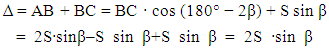
- Multipath error is caused by nearby reflecting surfaces at the receiver location. Just as light reflects off a shiny surface, radio signals can be reflected by solid objects and surfaces. GPS signals cannot penetrate solid objects like buildings, thick tree canopies, cars, ships, and bridges. Instead, these objects deflect them, causing the signals to arrive at the receiver via multiple paths. The reflected signals will interfere with the signals that are received via a direct path. The reflected signal travels for a longer time instead of traveling a direct signal path. As a result, this causes the receiver position to be calculated incorrectly, with the position shifting in the direction of the multipath source. The multipath distorts the C/A-code and P-code modulations, as well as the carrier phase observations. (Ogaja and Clement, 2011). Fortunately the multipath disturbance has a periodic characteristic and is repeated every sidereal day for a static receiver if the antenna environment remains the same (Gulie, 2014). since the GPS satellite ground tracks repeat every sidereal day, the multipath errors experienced today, for example, from 1:00pm – 2:00pm will be very similar to those experienced tomorrow, but will occur from 12:56pm – 1:56pm, provide the antenna environment remains unchanged (Ge et al., 2001).This repetition can then be useful for verifying the presence of multipath through the analysis of observations made at static receiver on different days. Alber et al. (2000), developed a multipath simulation model and described where in the multipath parameters can be varied and their influences are observed. The parameters included are the reflection coefficient, the antenna to reflector distance, the azimuth and elevation of the reflected signal the existence of multiple reflectors and satellite dynamics. Magnitude of the multipath depends on few factors (Kamarudin et al, 2004): i) Position of the reflected surface that located near the antenna.ii) Types of the reflected surface.iii) The height of antenna from the earth surface.iv) GPS wave distance signals.Yi et al, (2012), mentioned that The multipath signals are always delayed compared to the line of sight LOS signals because of the longer travel paths caused by reflections. From the geometrical relations shown in figure 1, the wave path difference ∆ between indirect and direct signal lengths from the satellite antenna to the receiving antenna can be calculated as follows:
 | (1) |
 | (2) |
 | (3) |
 | (4) |
 is the direct signal, SM(t) denotes the reflected signal, A indicates the amplitude of the direct signal, ω0 stands for the angular frequency, and
  and
and  represent the reflection coefficient
  and the phase delay of the reflected signal i, respectively.
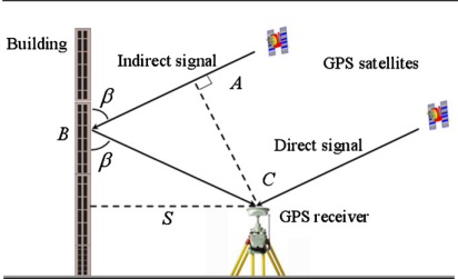 | Figure 1. Multipath: geometry of a signal, a reflector and a receiver antenna |
 | (5) |
 | (6) |
 and
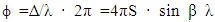
and  respectively represent the reflection coefficient of superposed signal and the phase delay of the superposed signal relative to the direct signal, which can be given by the following equations:Analysing equations (2) and (6), one can see that the multipath is characterized by four parameters: the reflection coefficient α, the distance S of the reflector to the antenna phase centre, the angle of incidence of the satellite signal β and the carrier wavelength λ.
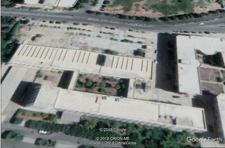 | Figure 2. The experiment area and the locations of reference (stationary) and the test (rover) receivers |
4. Test Field and Materials
- The test field chosen for all the multipath geometry experiments is established in Al-Azhar University on the roof of Civil Engineering Faculty Building, Cairo, Egypt.
4.1. Test 1: Types of the Reflected Surface
- We choose the roof where there is no multipath from surroundings except from the panels under study cases for the purpose of generating the multipath So the multipath variations that are observed are due to variation in the electrical properties of the surface material. Two receivers are used, both of which are of Trimble System R4 (Model 3). One of them is put on station (a2) as a Base (control point), the other on station (a1) as a Rover. The distance between the two receivers was about 10 m. Receiver parameters were set as follows: data logging interval 1 seconds, elevation mask 10°, PDOP value of 5 (To ensure high-precision GPS positioning, a PDOP value of 5 or less is usually recommended. In practice, the actual PDOP value is usually much less than 5(DINESH et al, 2010)).The GPS data observations were made in 4 successive days from 30/01/2016 to 3/02/2016 with gap 1/02/2016. The observations were measured during the same time over the same point every day 1.25 hrs duration. The orbital period of GPS constellation is of 11hours and 56 minutes which implies a satellite will be at the same location in the sky about four minutes earlier each day. This difference was incorporated in extracting the observables. The heights of the reflector at 1m distance from Rover were obtained according to the receiver’s minimum satellite elevation angle (10)The material used are (aluminium, glass, wood)- The test includes the following two parts.- On the first day, the tests were taken over the roof in open environment and no obstructed material for the two antenna. The GPS receivers are set up on the reference and rover (both fixed) stations.- On the other three successive days, the tests are conducted for the panels made of different construction materials. The GPS receivers are set up on the reference and rover (both fixed) stations. the panel reflector was placed during consecutive days at 1 m from the rover’s receiver at the same direction. The tests are conducted for the panels (dimensions of 1 × 1 m) made of aluminium, glass, and wood. On the second day, the multipath tests commenced with aluminium panel. On the third day the glass panel was used. On the fourth day, the wood panel was used.
5. Results and Analysis
- The software using is Leica Geo Office.After the dataset collected for four days are superposed to maintain the same satellite configuration, the observations obtained under the multipath geometries are investigated by comparing them against the non-multipath observations (control group). The double differences are utilized in the analyses since the atmospheric (ionospheric and tropospheric) effects, satellite-receiver clock offsets and orbit errors are mostly cancelled out for short baselines (here < 1km) GPS observations (Collins and Langley, 1996). As far as the multipath and non-multipath observations are concerned, since the only difference between them is the presence or absence of reflecting panels.one can deduct that the difference between these data is assumed to emerge from the multipath error plus random error. However, when comparing the results from the multipath geometries to the ones from the control data, the difference still significantly represents the multipath errors since the same random errors occur during the control observations and is presumed to cancels out on differencing. In order to see the differences between the static (true) and multipath coordinates of the test point, the initial changes are charted against three Directions, namely Earth, North and Height.
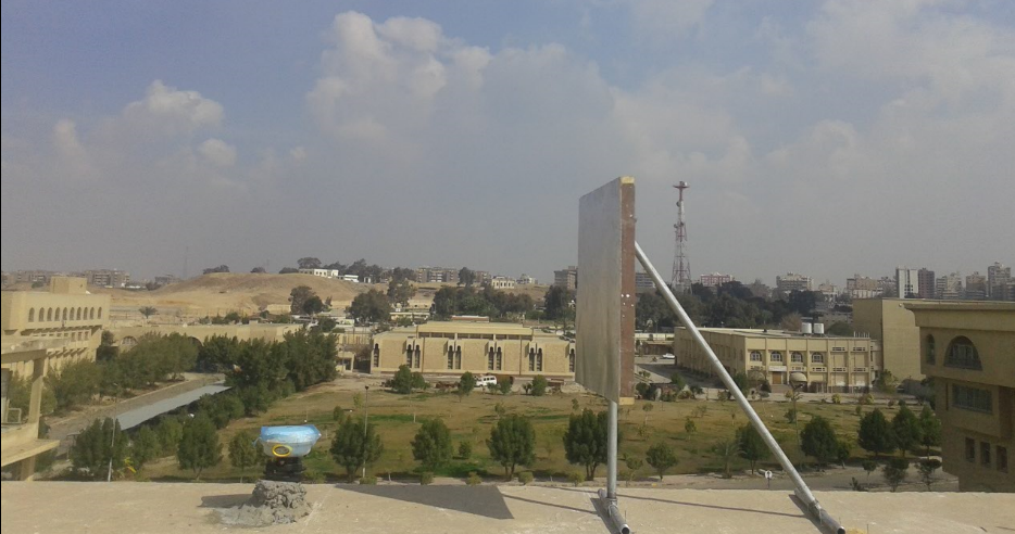 | Figure 3. Vertical reflecting panel (1mX1m). away 1m from the receiver(Rover) |
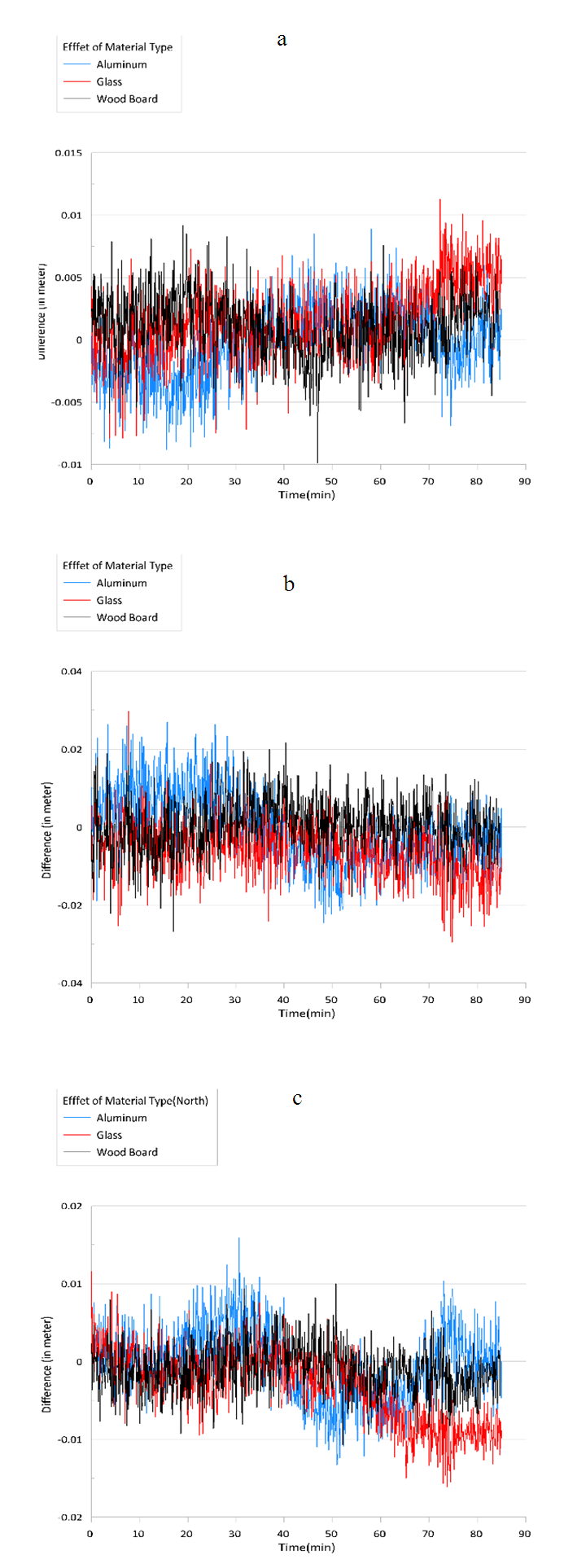 | Figure 4. Changes in Directions, a) Changing in East, b) Changing in North, c) Changing in Height |
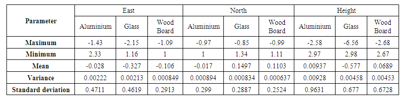 | Table 1. Difference results in East, North, Height Directions (unit: cm) |
6. Conclusions
- Based on the results of this study, it was found that the multipath signals from the panels caused an increase in error coordinates values, it is observed that aluminium caused the highest amount of multipath. This is followed by glass and wood.