-
Paper Information
- Paper Submission
-
Journal Information
- About This Journal
- Editorial Board
- Current Issue
- Archive
- Author Guidelines
- Contact Us
American Journal of Geographic Information System
p-ISSN: 2163-1131 e-ISSN: 2163-114X
2018; 7(2): 67-74
doi:10.5923/j.ajgis.20180702.03

Towards Automated Generation of True Orthoimages for Urban Areas
 Abstract
 Reference
 Full-Text PDF
 Full-text HTML
Mehad Haggag, Mohammed Zahran, Mahmoud Salah
Department of Surveying Engineering, Shoubra Faculty of Engineering, Benha University, Cairo, Egypt
Correspondence to: Mehad Haggag, Department of Surveying Engineering, Shoubra Faculty of Engineering, Benha University, Cairo, Egypt.
| Email: |  |
Copyright © 2018 The Author(s). Published by Scientific & Academic Publishing.
This work is licensed under the Creative Commons Attribution International License (CC BY).
http://creativecommons.org/licenses/by/4.0/

True orthoimage generation has become one of the most investigated research topics motivated by the growing technology of high resolution image acquisition. Conventional orthophotos are based on differential rectification in their production. Unfortunately, in large scale urban imagery differential rectification produces a serious problem in the form of double mapped areas called “ghosting effects”. True orthoimage generation techniques try to remove this ghost effect by detecting the occluded or obscured areas, marking them as blank, filling them from the neighbouring images and finally treat shadowed areas. This paper presents a method for true-orthoimage generation from high resolution aerial imagery. The method compromises three main steps: (i) image orientation based on collinearity equations/bundle block adjustment, (ii) Digital surface model (DSM) using semi-global matching (SGM) technique, and (iii) true-orthoimage generation. The obtained true-orthoimage is a rigorous one with no self-occlusions, ghost effects and multiple texture mapping. The use of semi-global matching for DSM generation has developed promising results for orthoimage generation. Using an accurate DSM generated from image itself refined from occlusions and outliers eliminates the serious ghost effect with no need for subsequent steps for occlusion detection and elimination.
Keywords: Automation, Semi global matching, DSM, True orthoimage
Cite this paper: Mehad Haggag, Mohammed Zahran, Mahmoud Salah, Towards Automated Generation of True Orthoimages for Urban Areas, American Journal of Geographic Information System, Vol. 7 No. 2, 2018, pp. 67-74. doi: 10.5923/j.ajgis.20180702.03.
Article Outline
1. Introduction
- The orthorectification process assumes that each image pixel has an accurate ground coordinates represented in the digital surface model (DSM). Given the ground X, Y, and Z coordinates of the object point and the sensor parameters collinearity condition equations can be applied to determine the image coordinates of the object point. After reaching the image position the intensity value of this image point is assigned to its corresponding location in the orthoimage.Most of orthoimage generation problems originates from the non-corresponding representation between image and DSM. The first problem originates from the non-complete digital surface modeling. Traditional orthoimage production uses digital terrain models (DTM) representing the topography of terrain without representing the detailed man made features on the ground. These man-made features cannot be rectified correctly and the top and bottom of these objects are projected as two points still displaced from each other as shown in figure 1 on the left hand where a DTM is considered. Starting from point A on the ground and applying collinearity condition we will reach to the image point of the building wall and then assigning its intensity value g(a) to the position of point A on orthoimage plane. All intensity values that would be assigned to points from A to B represent the wall of the building. Applying back projection of terrain points from B to C lead to image points of the roof of the building. Thus, the wall appears in the resulting orthoimage and the building roof does not appear in its right location. To overcome this problem a complete representation of the surface is required, in which all surface features such as trees and man-made features are represented. Referring to the right hand side of the figure 1 the terrain and building are represented in the DSM. Points before E are terrain points that when projected to the image plane will correctly lead to image points related to ground. Also, points from E to F are roof points that when projected will lead to image points related to the roof. As noticed there are no walls represented in the orthoimage generated with DSM, which means that all surface features are rectified correctly.
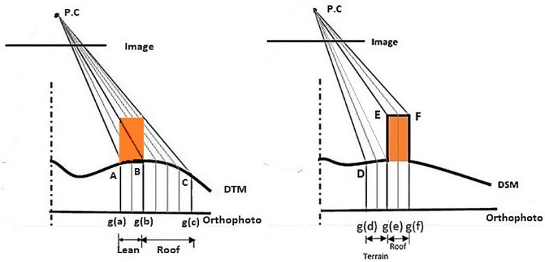 | Figure 1. The conventional DTM on left hand side and the right handed is DSM with building represented |
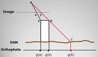 | Figure 2. Double Mapping (Ghost Effect) |
2. Literature Review
- As discussed above the main artifact in orthoimage generation in large scale urban areas where high buildings obscure the ground or hide each other is the double mapping or ghost effect. True orthoimage generation methods focus on how to find the areas hidden on the image by other higher objects and mark them as blank and try to fill them from other views if possible. Amhar et al. [10] proposed a methodology for making true orthoimages using DTM and digital building models (DBM) in which the building heights are only represented. In this methodology, two orthoimages, one corresponds to the terrain while the other corresponds to the buildings, are independently generated. The final true orthoimage is created by combining the terrain and building orthoimages.The Z-buffer method [11-14] resolves the ambiguity of which object point should be assigned to the image location by considering the distances between the perspective center and the object points in question. Among the competing object points, the closest point to the perspective center is considered visible while the other points are judged to be invisible in that image. This method was sensitive to the sampling interval of the digital elevation model (DSM) relative to the ground sampling distance (GSD) of imaging sensor.A polygon-based method was proposed by Kuzmin et al. [15] for the detection of obscured areas for true orthoimage generation. In this method, conventional differential rectification is first applied. Afterwards, hidden areas are detected by projecting polygonal surfaces, which are generated from a DBM, onto the image plane. Habib et al. [17] proposed two new methodologies for occlusion detection in which the presence of occlusions can be discerned by sequentially checking the off-nadir angles to the lines of sight connecting the perspective center to the DSM points along a radial direction starting from the object space nadir point. Another method for occlusion detection is the Multi-Visibility Analysis of the object [18]. This method performs an analysis of the radial angular visibility from the terrain point, in the nadiral direction of each image in which this point appears. Projective methodology for occlusion detection was discussed in Volotão [20] and Wang and Xie [21]. This method adopts the way of projecting roof and wall polygons to the ground horizontal planes using direct collinearity equations, and obtains the occlusions by iteration strategy. Oliveira and Galo [22] presented a method for occlusion detection based on height gradient computations applied to a DSM of the region. These height gradients computed in radial directions are important for the identification of the beginning of the occlusions in these directions. The final limits of the occlusions are obtained from the projection of these initial points in the DSM. Yong Hu et al. [27] proposed an elevation buffer (e-buffer) technique for occlusion detection employing the plain elevations instead of the distances from perspective center by z-buffer, This method does not depend on the perspective center so it is applicable for all types of imaging sensor models. The drawback of this method is the sensitivity to the direction of the building roofs with respect to the imaging line of sight.After occlusion detection and ghost effect elimination these methods combine multiple images captured from different points of view so that occluded areas in one image can be filled by images from other views [1-5]. In general, the quality of any orthoimage depends on image resolution, accuracy of the estimated camera calibration and orientation parameters, and density of the applied DSM [6]. It is worth mentioning that elimination of the ghost effect in these methods is done by finding the parts of orthoimage that is double mapped. This is performed by comparing the DSM candidate cells that have the same intensity values by measuring distances or angles from perspective center or by measuring gradients within the DSM itself. In this research, the main idea of the proposed method for true orthoimage generation is to use a pixelwise DSM generated from images itself filtered from occlusions and hidden areas, i.e., has empty cells in these regions and then projecting it to image plane. The empty or no data DSM cells will be skipped in orthorectification process and there is no intensity values would be assigned to these cells, leading to no double mapping. To generate such DSM a very accurate and dense matching algorithm should be applied. In computer vision community there is a suitable matching algorithm referred to as Semi-Global Matching (SGM) developed by Hirschmüller [9]. This matching algorithm tries to match all pixels and imposes restrict conditions that filters out occlusions and outliers. Hirschmüller [16] used the pixel-wise SGM stereo technique for occlusion detection, subpixel refinement and multi-baseline matching. The mutual information-based matching cost has been applied to compensate for radiometric differences of images. The results showed that SGM is suited for reconstruction from huge aerial and pushbroom images, in case of subpixel accuracy.Gehrke et al. [19] compared the SGM method against LiDAR in terms of DSM/DEM resolution and accuracy. The results showed that SGM can be used as an alternative to LiDAR for high resolution DSM generation and orthoimage generation. Haala [8] used the SGM stereo method for a pixel-wise matching of highly overlapping aerial imagery to generate dense 3D point clouds. The results confirmed that SGM has efficiently increased the accuracy and reliability of the obtained results.Michael et al. [23] applied a stereo vision system based on non-parametric rank transform and SGM. The system covers the entire stereo vision process and includes noise reduction, rectification, disparity estimation and visualization. The results confirmed that the system is applicable in terms of frame rate and high resolution. Dall'Asta and Roncella [24] compared the SGM and the Local Dense Matching (LSM) algorithms for DSM generation based on real and simulated stereo. The comparison showed that SGM provided much better results than LSM which produced noisy data especially in low-contrast and blurred areas. Gong and Fritsch [25] presented a comprehensive study about the DSM generation from WorldView-2 stereo satellite imagery. The Bundle Block Adjustment based on bias-compensated Rational Polynomial Coefficients (RPCs) has been applied for image orientation and rectification. In terms of robustness and precision, the results have verified that very dense DSMs can be generated from high resolution satellite imagery. d’Angelo [26] applied the more global matching (MGM) technique to improve the regularization step of the SGM based on a Pleiades Triplet and a Cartosat-1 Stereo pair. The results showed that the MGM cost aggregation slightly increased the accuracy of the obtained results.
3. Study Area and Data Used
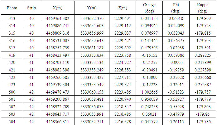
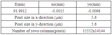
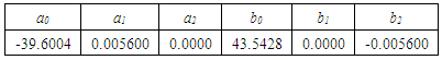
- The area to be processed has a size of 1.2 x 1.3km in the city of München. The imagery captured by the DMC II 230 camera. The aerial images were collected at height above datum of 2225m and a ground sampling distance (GSD) of 10 cm. The block consists of three strips with 5 images each as shown in figure 3. The available overlap of 80% in flight and 80% cross flight, results in a considerable redundancy of up to fifteen-folded object points. Table 1 presents the exterior orientation parameters of the block images. The rotation angles between image and object space is defined as follows: Omega: X as Primary; Phi: Y as Secondary; and Kappa: Z as Tertiary. Table 2 represents the interior orientation parameters for the camera used as indicated in the camera calibration file.
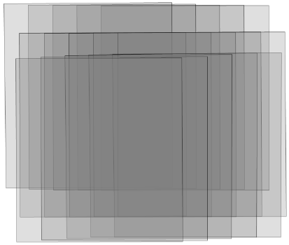 | Figure 3. A block containing three strips of imagery |
|
|
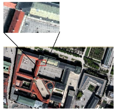
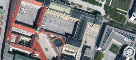 | Figure 4. Typical view of the raw image data |
4. Methodology
- Orientation of the Images within the block is a fundamental prerequisite for any metric reconstruction from these images. Thus, the operational procedure for true-orthoimage generation involves three phases; aerial triangulation starting from the known exterior orientation and camera calibration parameters, automated dense image matching for DSM generation, and true-orthoimage generation from the generated DSM.
4.1. Aerial Triangulation
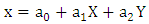
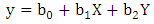
- 2D affine transformation has been applied to transform the pixel coordinates (the origin is at the upper left corner of the image) to film coordinates (the origin is the principal point) using the following equations:
 | (1) |
 | (2) |
 | (3) |
 | (4) |
4.2. DSM Generation by High Density Image Matching
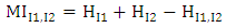
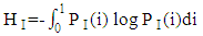
- The orthorectification process assumes that each image pixel has 3D ground coordinates. All problems related to large scale orthoimages in urban areas originate from the non-correspondence between the information recorded on the image with these on the DSM. If there are more details recorded on the image than these represented in the DSM, these features will not rectified correctly. Also, if there is more information about the surface represented in the DSM and hidden in image by reliefs of tall features, the double mapping effect will appear in the resulted image. Thus, to overcome all the above problem we need a detailed digital surface model with the same cell size as the ground sampling distance (GSD) of the image pixel and produced from these images themselves (i.e. pixel wise DSM). With the advances in digital airborne camera technology automatic image based 3D surface construction is highly motivated. Thus, high density image matching algorithms have been introduced. Dense image matching algorithms obtain the corresponding points for almost all pixels in the image rather than defining interest points or features and trying to match them. They compare the overlapping image row by row which assumes that epipolar geometry is determined first. Then, for each pixel they search in the corresponding row for the pixel with best match. The disparity (or parallax) is stored for each pixel in a disparity map. Finally, the 3D position is computed by the traditional photogrammetric techniques.Semi-global matching is anew matching algorithm developed by Hirschmüller [28, 29]. The main idea of the algorithm is a computation of per-pixel matching costs utilizing the radiometrically robust mutual information and disparity map. Mutual information is the measure of similarities between two random variables based on their probability distribution. It is a measure of how much information is communicated in one random variable with another. If one random variable indicates something about the other then these two variables share mutual information. If the mutual information between the two variables is zero then these variables are independent. The advantage of using mutual information over intensity based matching algorithms in image matching is that they are not sensitive to illumination and recording changes between the two images. Also, the use of a correlation window in intensity based matching algorithms causes blurred effects on object boundaries.Mutual information is defined from the entropy H of two images as well as their jointed entropy
 | (5) |
 | (6) |
 | (7) |
 | (8) |
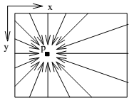 | Figure 5. Paths from all directions r |
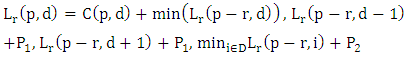 | (9) |
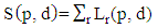 | (10) |
 | (11) |
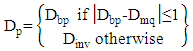
4.3. True-Ortho Image Mapping
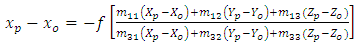
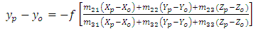
- The orthorectification process takes the raw aerial imagery and applies the created DSM refined from occlusions and outliers as indicated in equation (11) and the obtained aerial triangulation results to create a true-orthoimage. Relief displacement has been corrected by determining the equivalent position in the image for each pixel in the DSM. By resampling of the surrounding pixels, intensity value can be determined. Figure 6 illustrates how to find the intensity values of a true-orthoimage. In the figure, P is the ground point; P1 is the image point; O is the perspective center (origin); X and Z are the ground coordinates in the DSM; and f is the focal length.
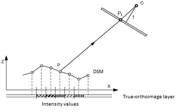 | Figure 6. Finding the intensity values of a true-orthoimage |
5. Results and Discussions
- At the beginning, the 2D affine transformation has been applied to transform the pixel coordinates to film coordinates. The obtained six transformation parameters (a0, a1, a2, b0, b1 and b2) defining the scale, shift and rotations between the two coordinate systems are given in table 3. Once the transformation parameters are determined, the pixel coordinates can be transformed to film coordinates. After that, aerial triangulation has been performed using a bundle block adjustment based on collinearity equations; yielding a fraction of a pixel as a measure of global quality.
|
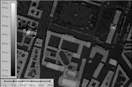 | Figure 7. The generated DSM with the 10cm cell size |
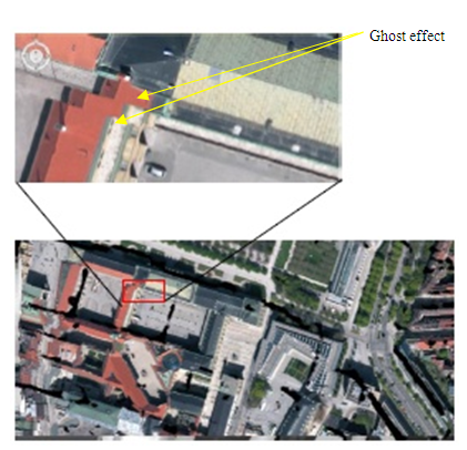 | Figure 8. Orthoimage generated by traditional methods with leans, walls, unrectified objects and serious ghost effects |
 | Figure 9. True orthoimage generated using DSM generated with semiglobal matching algorithm |
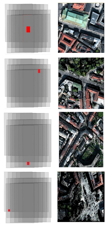 | Figure 10. Different views from the generated true-orthoimage. Left column: the position of the image in the block marked in red colour; right column: the obtained true-orthoimage |
6. Conclusions
- In order to generate a true orthoimage for a large scale urban imagery we presumes that each pixel in the imagery has a correct 3D ground coordinates. Thus, a very precise and high detailed DSM is required. Implementing high density image matching algorithms such as semi-global matching for DSM generation produces high accurate digital surface models with cell size in the same size of digital image ground sampling distance. Due to restricted matching criterion the matching results of occluded areas are voided. Therefore, almost all occluded areas and shadows disappear from the orthoimage generated using these digital surface models. This saves the hard and time consuming tasks of occlusion detection and elimination procedures. The drawbacks of this method are the processing time and capabilities for generating these high accurate digital surface models especially in dense built up urban areas. As a future work, a global optimization algorithm has to be tested in order to improve the regularization performance of the SGM algorithm.
ACKNOWLEDGEMENTS
- The authors would like to thank the data providers for their generous support.