| [1] | A. Castillejos and J. Brimacombe. Measurement of physical characteristics of bubbles in gas-liquid plumes: Part II. Local properties of turbulent air-water plumes in vertically injected jets. Metall. Trans. B, 18B, 659–671 (1987). |
| [2] | A. Fujiwara, D. Minato, and K. Hishida, Effect of Bubble Diameter on Modification of Turbulence in an Upward Pipe Flow, International Journal of Heat and Fluid Flow, 25 (2004) 481-488. |
| [3] | Abdel-Aal H. K., Stiles G. B. and Holland C. D. 1966. Formation of Interfacial Area at High Rates Gas Flow Through Submerged Orifices. ALCHE J. 12, pp. 174-180. |
| [4] | Abdulmouti H., Murai Y., Ohno Y., Yamamoto F. 2000. Measurement of Bubble Plume Generated Surface Flow Using PIV, Journal of the Visualization Society of Japan. Vol. 21. No. 2. Pp. 31-37. |
| [5] | Abramovich, G. N. (1963). The theory of turbulent jets, MIT, Cambridge, Mass. |
| [6] | Akagawa, K., and T. Sakaguchi, 1966, "Fluctuation of Void Ratio in Two-Phase Flow (2nd Report, Analysis of Flow Configuration Considering the Existence of Small Bubbles in Liquid Slugs) and (3rd Report, Absolute Velocities of Slugs and Small Bubbles, and Distribution of Small Bubbles in Liquid Slugs)," Bulletin of JSME, Vol. 9, No. 33, pp. 104-120. |
| [7] | Akagawa, K., Sakaguchi, T., Fujii, T., Sugiyama, M., Yamaguchi, T., and Ito, Y. (1979). “Shock phenomena in bubble and slug flow regimes.” Two-Phase Flow Dynamics, Japan–U.S. Seminar, A. B. Bergles and S. Ishigai, eds., Hemisphere Publishing, Washington, DC, 217–238. |
| [8] | Akagawa, K., Sakaguchi, T., Fujii, T., Fujioka, S., and Sugiyama, M. (1980). “Shock phenomena in air-water two-phase flow.” Proc., Multiphase Flow and Heat Transfer Symposium Workshop, Vol. 3, Hemisphere Publishing, Washington, DC, 1673–1694. |
| [9] | Akagawa, K., Fujii, T., and Ito, Y. (1983). “Analyses of shock phenomena in a bubbly flow by two-velocity model and homogeneous model.” Advances in two-phase flow and heat transfer, fundamentals and applications, |
| [10] | Akasaka, Y., Kawaguchi, T., and Maeda, M. (2002). Application of interferometric laser imaging technique to a transient spray flow. In 11th International Symposium on Applications of Laser to Fluid Mechanics, Lisbon. |
| [11] | A.K. Das and P.K. Das. Modelling bubbly flow and its transitions in vertical annuli using population balance technique. International Journal of Heat and Fluid Flow 31 (2010) 101–114. |
| [12] | Akita, K., Nakanishi, O. and Tsuchiya, K., 1994, Turn-around energy losses in an external-loop airlift reactor, Chem Eng Sci, 49: 2521. |
| [13] | Akhtar, M. A., Tadé, M. O. and Pareek, V. K. (2006), "Two-fluid Eulerian simulation of bubble column reactors with distributors", Journal of Chemical Engineering of Japan, vol. 39, no. 8, pp. 831-841. |
| [14] | A. Kubota, H. Kato, and H. Yamaguchi, “A new modeling of cavitating flows: A numerical study of unsteady cavitation on a hydrofoil section,” J. Fluid Mech. 240, 59 (1992). |
| [15] | Alam M. and Arakeri V. H., Observations on Transition in Plane Bubble Plumes. J. Fluid Mech., 254, 1993, 363-380. |
| [16] | Al Tawell A. M. and Landau J. 1977. Turbulence Modulation in Two-Phase Jets. Int. J. Multiphase Flow 3, pp. 341-353. |
| [17] | Alexander B. Tayler. Experimental Characterisation of Bubbly Flow using MRI. Trinity College. Ph. d. Thesis. May 2011. The University of Cambridge. |
| [18] | American, S., 2021. Scientific American. Available at: https://www.scientificamerican.com/article/the-bubbles-produced-by-u/. |
| [19] | Antoniadis, D., Mantzavinos, D., and Stamatoudis, M. (1992). Effect of chamber volume and diameter on bubble formation at plated orifices. Transactions of the Institution of Chemical Engineers, Part A, 70, 161-165. |
| [20] | Apazidis, N., 1985, "Influence of Bubble Expansion and Relative Velocity on the Performance and Stability of an AirLift Pump," International Journal of Multiphase Flow, Vol. 11, No.4, pp. 459-475. |
| [21] | A. Prosperetti, “The thermal behavior of oscillating gas bubbles,” J. Fluid Mech. 222, 587 (1991). |
| [22] | Arega, F., and J. H. W. Lee (2005), Diffusional mass transfer at sediment-water interface of cylindrical sediment oxygen demand chamber, J. Environ. Engineer., 131(5), 755-766. |
| [23] | Arnold, H., Yadigaroglu, G., Gonzales, A., Rao, A. S., 1997. An economic passive plant design. Jahrestagung Kerntechnik 97. Aachen, Germany. |
| [24] | Asaeda, T., and Imberger, J. (1989). “Behaviors of bubble plumes in a linear stratification.” J. Jpn. Soc. Civ. Eng., 411, 55–62 (in Japanese). |
| [25] | Asaeda, T., and Imberger, J. (1993). “Structure of bubble plumes in linearly stratified environments.”. J. of Fluid Mechanics, Vol. 249, pp. 35-57. |
| [26] | Ashfaq Shaikh and Muthanna H. Al-Dahhan. A Review on Flow Regime Transition in Bubble Columns. International Journal of Chemical Reactor Engineering. Volume 5. 2007 Review R1. |
| [27] | Asher, W. E., and P. J. Farley (1995), Phase-Doppler anemometer measurement of bubble concentrations in laboratory-simulated breaking waves, J. Geophys. Res., 100, 7045–7056. |
| [28] | Asher, W. E., L. M. Karle, B. J. Higgins, P. J. Farley, E. C. Monahan, and I. S. Leifer (1996), The influence of bubble plumes on air-seawater gas transfer velocities, J. Geophys. Res., 101(C5), 12,027–12,041, doi:10.1029/96JC00121. |
| [29] | Ashley, K. I. (1985), Hypolimnetic aeration: Practical design and application, Water Res., 19(6), 735-740. |
| [30] | Ashley, K. Hay, S., Scholten, GH., (1987), Hypolimnetic aeration: Field test of the empirical sizing method, Water Res., 21(2), 223-227. |
| [31] | Ashley, K. I. (1988), Hypolimnetic aeration research in British Columbia, Verh. Internat. Verein. Limnol., 23(1), 215-219. |
| [32] | Asiagbe, K. S., Fairweather, M., Njobuenwu, D. O., & Colombo, M. (2017). Large eddy simulation of microbubble transport in vertical channel flows. In Computer Aided Chemical Engineering (Vol. 40, pp. 73-78). Elsevier. |
| [33] | Atila P. Silva Freire, Davi D’E. Miranda, Leonardo M.S. Luz, Guilherme F.M. Franc_a. Bubble plumes and the Coanda effect. International Journal of Multiphase Flow 28 (2002) 1293–1310. |
| [34] | A. Tomiyama, Drag, lift and virtual mass forces acting on a single bubble, in Proc. of the 3rd International Symposium on Two-Phase Flow Modelling and Experimentation, Edizioni ETS, Pisa, Italy (2004). |
| [35] | A. T. Preston, T. Colonius, and C. E. Brennen, “A numerical investigation of unsteady bubbly cavitating nozzle flows,” Phys. Fluids 14, 300 (2002). |
| [36] | A. T. Preston, T. Colonius, and C. E. Brennen, “A reduced-order model of diffusive effects on the dynamics of bubbles,” Phys. Fluids 19, 123302 (2007). |
| [37] | Avanish Mishra. Numerical And Experimental Investigation Of A Confined Plunging Liquid Jet System. MSc (Research). Cranfield University. 2011. |
| [38] | Autumn Fjeld and James W. Evan. Characterization of Droplets Produced by Bubbles Bursting: San Francisco, CA. TMS 2005 (134th) Annual Meeting: Technical Program. |
| [39] | A.W.G. de Vries. Path and Wake of a Rising Bubble. ISBN 90 365 15262. 2001. Enschede, The Netherlands. |
| [40] | Aubin, J., Sauze, L.N., Bertrand, J., Fletcher, D., Xuereb, C., PIV measurements of flow in an aerated tank stirred by a down- and an up-pumping axial flow impeller. Experimental Thermal and Fluid Science, Vol. 28, 447-456 (2004). |
| [41] | Baines W. D. and Hamilton G. F. 1959. On the Flow of Water Induced by a Rising Column of Air Bubbles. Intl Assoc. For Hydraulic Research, Proceedings of 8th Congress., Monteral, 24-29 August, pp. 7D1-7D17. |
| [42] | Baines W. D. 1961. The Principles of operation of Bubbling Systems. Proc. Symp. Air Bubbling, Ottawa. |
| [43] | Baines W. D. 1983. A Technique for the Direction Measurement of Volume Flux of a Plume. J. Fluid Mech. 132, 247-256. |
| [44] | Baines W. D. and Leitch A. M. 1992. Destruction of Stratification by Bubble Plume. Journal of Hydraulic Engineering. Vol. 188, No. 4, April, 1992. No. 26602. Pp. 559-577. |
| [45] | Balasubramanian, P. and Kandlikar, S.G. Experimental study of flow patterns, pressure drop, and flow instabilities in parallel rectangular minichannels. Heat Transfer Engineering, Volume 23, 20-27 (2005). |
| [46] | Baltimore, Maryland, August 2–6, 1992. Published by American Society of Civil Engineers. Hydraulics Research Station. 1978. "Air Bubbles for Water Quality Improvement," Report No. 00/12, April, Hydraulics Research Station, Wallingford, England. |
| [47] | Bankovic A., Currie, I. G. and Martin W. W. 1984. Laser-Doppler Measurements of Bubble Plumes. Phys. Fluids 27, pp. 348-355. |
| [48] | Barbosa, J.R.J., Bradbury, L.J.S., 1996. Experimental investigations in round bubble plumes. In: Proc. 6th Brazilian National Meeting on Thermal Sciences (ENCIT), Florianopolis, pp. 1073–1078. |
| [49] | Bauer, M., Eigenberger, G., 1999. A concept for multi-scale modelling of bubble columns and loop reactors, Chemical Engineering Science, 54, 5109-5117 |
| [50] | Bauer, M., Eigenberger, G., 2001. Multiscale modeling of hydrodynamics, mass transfer and reaction in bubble column reactors, Chemical Engineering Science, 56, 1067-1074 |
| [51] | Bardina, J., Ferziger, J. H. and Reynolds, W. C. (1980) Improved Subgrid Models for Large Eddy Simulation. AIAA paper, 1980. |
| [52] | Baschek, B., and D. M. Farmer (2010), Gas bubbles as oceanographic tracers, J. Atmos. Oceanic Technol., 27, 241–245. |
| [53] | Becker, S., Sokolichin, A. and Eigenberger, G. (1994), "Gas-liquid flow in bubble columns and loop reactors: Part II. Comparison of detailed experiments and flow simulations", Chemical Engineering Science, vol. 49, No. 24, pp. 5747-5762. |
| [54] | Becker, S., De Bie, H. and Sweeney, J. (1999), "Dynamic flow behaviour in bubble columns", Chemical Engineering Science, vol. 54, no. 21, pp. 4929-4935. |
| [55] | Beer, H.; Durst, F.: Mechanismen der Wärmeübertragung beim Blasensieden und ihre Simulation. Chemie Ingenieur Technik, 40/13, 632-638, (1968). |
| [56] | B. Eisenberg, L. L. Ansel, R. A. Fiato, and R. F. Bauman, Advanced gas conversion technology for remote natural gas utilization, GPA Convention, New Orleans, Louisiana (1994). |
| [57] | Bel Fdhila, R., Simonin, O., 1992. Eulerian prediction of a turbulent bubbly flow downstream of a sudden pipe expansion. Workshop on Two-phase flow predictions, 30 March–2 April, Erlangen. |
| [58] | Benjamin, R.J.; Balakrishnan, A.R.: Nucleate pool boiling heat transfer of pure liquids at low to moderate heat fluxes. International Journal of Heat and Mass Transfer, 39,2495-2504, (1996). |
| [59] | Bendiksen, K. (1985). On the motion of long bubbles in vertical tubes. Int. J. Multiphase Flow, Vol. 11(6), 797- 812. |
| [60] | Bernard, R.S., 1995. Preliminary Development of a Three-dimensional Numerical Model for Reservoir Hydrodynamics. Technical Report HL-95-9, Waterways Experiment Station. US Army Corps of Engineers, Vicksburg, MS. |
| [61] | Bernard, R. S. 1997. ‘‘Extension and validation of the MAC3D numerical model for applications involving bubble diffusers.’’ Proc., Int. Association of Hydraulic Research Congress on Environmental and Coastal Hydraulics, ASCE, New York, 833–838. |
| [62] | Bernard, R.S., 1998. MAC3D: Numerical Model for Reservoir Hydrodynamics with Application to Bubble Diffusers. Technical Report CHL-98-23, Waterways Experiment Station. US Army Corps of Engineers, Vicksburg, MS. |
| [63] | Bernard, R.S., Maier, R.S., Falvey, H.T., 2000. A simple computational model for bubble plumes. Applied Mathematical Modelling 24, 215e233. |
| [64] | Bernard, R.S., 2002. User’s Manual for the PAR3D Numerical Flow Model, Version 2.0. ERDC Waterways Experiment Station. US Army Corps of Engineers, Vicksburg, MS. |
| [65] | Beutel, M. W., and A. J. Horne (1999), A review of the effects of hypolimnetic oxygenation on lake and reservoir water quality, Lake Reservoir Manage., 15(4), 285-297. |
| [66] | Beutel, M. W. (2003), Hypolimnetic anoxia and sediment oxygen demand in California drinking water reservoirs, Lake Reservoir Manage., 19(3), 208-221. |
| [67] | Beylich, A. E., and Gülhan, A., 1990, “On the Structure of Nonlinear Waves in Liquids With Gas Bubbles,” Phys. Fluids A, 2-8, pp. 1412–1428. |
| [68] | B. H. Davis, Overview of reactors for liquid phase Fischer-Tropsch synthesis, Catal. Today 71, 249 (2002). |
| [69] | Bin, A. K. (1993), "Gas entrainment by plunging liquid jets", Chemical Engineering Science, vol. 48, no. 21, pp. 3585-3630. |
| [70] | B. Jager and R. Espinoza, Advances in low temperature Fisher-Tropsch synthesis, Catal. Today 23, 17 (1995). |
| [71] | B.J. Azzopardi. Multiphase Flow. Chemical Engineering and Chemical Process Technology - Vol. I – Encyclopaedia of Life Support Systems. ISBN: 978-1-84826-396-3 (eBook). ISBN: 978-1-84826-846-3 (Print Volume) 2012. |
| [72] | Boufadel, M. and Socolofsky, S., 2021. The Underwater Behavior of Oil and Gas Jets and Plumes. [online] Eos. Available at: <https://eos.org/editors-vox/the-underwater-behavior-of-oil-and-gas-jets-and-plumes>. |
| [73] | Bombardelli, F. A., Buscaglia, G. C., Rehmann, C. R., Rincón, L. E., and García, M. H. (2007). “Modeling and scaling of aeration bubble plumes: A two-phase flow analysis.” J. Hydraul. Res., 45_5_, 617– 630. |
| [74] | Borchers, O., Busch, C., Sokolichin A., Eigenberger, G., 1999, Applicability of the standard k−ε turbulence model to the dynamic simulation of bubble columns. Part II: Comparison of detailed experiments and flow simulations, Chemical Engineering Science, 54, 5927-5935. |
| [75] | Botton, R., Cosserat, D., Poncin, S. and Wild, G. (2009), "A simple gas-liquid mass transfer jet system", 8th World Congress of Chemical Engineering, Montréal, Canada. |
| [76] | Boulton-Stone J. M. and Blake J. R. 1993. Gas Bubbles Bursting at a Free Surface. J. Fluid Mech. 1993, Vol. 254, pp.437-466. |
| [77] | Boudreau, A., 2016. Bubble migration in a compacting crystal-liquid mush. Contrib Mineral Petrol (2016) 171:32. DOI 10.1007/s00410-016-1237-9. Petrology, 171(4). |
| [78] | Bravo R. Hector, John S. Gulliver, Miki Hondzo. Development of A Commercial Code-Based Two-Fluid Model For Bubble Plumes. Environmental Modelling and Software 22 (2007) 536-547. |
| [79] | Brevik, I. (1977), Two-dimensional air-bubble plume, J. Waterway, Port, Coastal, and Ocean |
| [80] | Div., Proc. American Soc. of Civil Engineers, 103(WW1), 101-115. |
| [81] | Brevik, I., and R. Killie (1996), Phenomenological description of the axisymmetric air-bubble plume, Internat. J. Multiphase Flow, 22(3), 535-549. |
| [82] | Brevik, I., and R. Kluge (1999), On the role of turbulence in the phenomenological theory of plane and axisymmetric air-bubble plumes Internat. J. Multiphase Flow, 25, 87-108. |
| [83] | Brevik, I., and Ø. Kristiansen (2002), The flow in and around air-bubble plumes, Int. J. Multiphase Flow, 28(4), 617– 634. ISSN 0301-9322, https://doi.org/10.1016/S0301-9322(01)00077-5. (https://www.sciencedirect.com/science/article/pii/S0301932201000775). |
| [84] | Brown, R. A. S., (1965). The mechanics of large gas bubbles in tubes I. Bubble velocities in stagnant liquids. Can. J. Chem. Eng., Vol. 43, pp. 217-223. |
| [85] | Brankovic A; Currie IG; Martin WW (1984) Laser-Doppler measurements of bubble dynamics. Phys Fluid 27: 348-355 |
| [86] | Brennen, C.E., Cavitation and Bubble Dynamics, Oxford Engineering Sciences Series 44, Oxford University Press, New York, (1995). |
| [87] | Bruijn, J., and H. Tuinzaad (1958), The relationships between depth of U-tubes and the aeration process, Journal of the American Water Works Association, 7, 879. |
| [88] | Bryant, R.A.A. (1975). “Water hammer incompressible fluids.” Rep.FM/18/ 75, University of Salford, Dept. of Mechanical Engineering, Salford, UK. |
| [89] | Bugg, J.D., K. Mack and K.S. Rezkallah (1998). Anumerical model of Taylor bubbles rising through stagnant liquids in vertical tubes. Int. J. Multiphase Flow 25(2), 271-281. |
| [90] | Bugg JD, Saad GA (2002). The velocity field around a Taylor bubble rising in a stagnant viscous fluid: numerical and experimental results. Int J Multiphase Flow 28:791–803. |
| [91] | Bulson, P. S., "Bubble Breakwater with Intermittent Air Supply," Res. Rept. 9-2, Military Eng. Exper. Estab., Christchurch, Hampshire, England, 1962. |
| [92] | Bulson, P. S., "Large Scale Bubble Breakwater Experiments," Res. Rept. 9-3, Military Eng. Exper. Estab., Christchurch, Hampshire, England, 1962. |
| [93] | Bulson P.S. 1968. The Theory and Design of Bubble Breakwaters. Proc. 11th Conf. Coastal Engng, London. 995. |
| [94] | Bunner, B. and G. Tryggvason, “Dynamics of homogeneous bubbly flows. Part 1: Rise velocity and microstructure of the bubbles,” J. Fluid Mech. 466, 17-52 (2002). |
| [95] | Bunner, B. and G. Tryggvason, “Dynamics of homogeneous bubbly flows. Part 2: Velocity fluctuations,” J. Fluid Mech. 466, 53 (2002). |
| [96] | Burke, J., Hess, C., and Kebbel, V. (2002). Digital holography for whole field spray diagnostics. In 11th international symposium on application of laser techniques to fluid mechanics, Lisbon. |
| [97] | Burris, V. L., and J. C. Little (1998), Bubble dynamics and oxygen transfer in a hypolimnetic aerator, Water Sci. Technol., 37(2), 293-300. |
| [98] | Burris, V. L., McGinnis, DF., Little, JC., (2002), Predicting oxygen transfer and water flow rate in airlift aerators, Water Res., 36(18), 4605-4615. |
| [99] | Buscaglia, G.C., Bombardelli, F.A., rouse, M.H., 2002. Numerical modeling of large-scale bubble plumes accounting for mass transfer effects. International Journal of Multiphase Flow 28 (11), 1763e1785. |
| [100] | Caballina, O., Climent, E., Dusek, J., 2003. Two-way coupling simulations of instabilities in a plane bubble plume, Physics of Fluids, 15(6), 1535-1544 |
| [101] | de Cachard, F. and Delhaye, J.M. 1996. A slug-churn model for small-diameter airlift pumps. Int. J. Multiphase Flow, Vol. 22, No. 4, pp. 627-649. |
| [102] | Caetano, E.F., 1984. Two-phase flow in a vertical annulus. TUFFP Report, University of Tulsa, OK. |
| [103] | Caetano, E.F., Shoham, O., Brill, J.P., 1992. Upward vertical two-phase flow through an annulus, Part I: single-phase friction factor, Taylor bubble rise velocity and flow pattern prediction. In: Proceedings of 4th International Conference on Multiphase Flow, Nice, France. |
| [104] | Caflisch, R. E., Miksis, M. J., Papanicolaou, G. C., and Ting, L., 1985, “Effective Equations for Wave Propagation in Bubbly Liquids,” J. Fluid Mech., 153, pp. 259–273. |
| [105] | Caflisch, R. E. M. J. Miksis, G. C. Papanicolaou, and L. Ting, “Wave propagation in bubbly liquids at finite volume fraction,” J. Fluid Mech. 160, 1 (1985). |
| [106] | Campbell, I. J., and Pitcher, A. S. (1958). “Shock waves in a liquid containing gas bubbles.” Proc. Royal Soc., Lon., Series A, 243, 534–545. |
| [107] | Campos JBLM, Guedes de Carvalho JRF (1988). An experimental study of the wake of gas slugs rising in liquids. J Fluid Mech 196: 27–37. |
| [108] | Cartellier, A. 1990 Optical probes for local void fraction measurements: characterization of performance. Rev. Sci. Instrum. 61 (2), 874- 886. |
| [109] | Carra, Sergio; Morbidelli, Massimo, (1987). Gas-liquid reactors. Chemical Industries (Dekker), 26(Chem. React. React. Eng.), 545-666. |
| [110] | Carrica, P., Bonetto, F., Drew, D., and Lahey, R. “The interaction of background ocean air bubbles with a surface ship.” Int. J. Numerical Methods in Fluids, 28:571-600, 1998. |
| [111] | Castello-Branco, M. A. S. C. and Schwerdtfeger, K. (1994) Large-Scale Measurements of the Physical Characteristics of Round Vertical Bubble Plumes in Liquids. Metallurgical and Materials Transactions B, 25B, 359-371, 1994. |
| [112] | Castro, W.E., P.B. Zielinski, and P.A. Sandifer, 1975, "Performance Characteristics of Airlift Pumps of Short Length and Small Diameter," Proceedings of the 6th annual meeting World Mariculture Society, |
| [113] | Chaudhry, M. H., Bhallamudi, S. M., Martin, C. S., and Naghash, M. (1990). “Analysis of transient pressures in bubbly, homogeneous, gas-liquid mixtures.” J. Fluids Eng., 112(2), 225–231. |
| [114] | Ceccio, S. L., and Brennen, C. E., 1991, “Observations of the Dynamics and Acoustics of Traveling Bubble Cavitation,” J. Fluid Mech., 233, pp. 633–660. |
| [115] | Cederwall, K., and J. D. Ditmars (1970), Analysis of Air-Bubble Plumes, W. M. Keck Laboratory of Hydraulics and Water Resources, Division of Engineering and Applied Science, California Institute of Technology, Pasadena, CA. |
| [116] | C. F. Delale, G. H. Schnerr, and J. Sauer, “Quasi-one-dimensional steadystate cavitating nozzle flows,” J. Fluid Mech. 427, 167 9(2001). |
| [117] | Chalmers, J. J. and Bavarian, F., 1991, Microscopic visualization of insect-bubble interactions. II: the bubble . lm and bubble rupture, Biotechnol Prog, 7: 151. |
| [118] | Chanson, H., Aoki, S. and Hoque, A. (2006), "Bubble entrainment and dispersion in plunging jet flows: Freshwater vs. seawater", Journal of Coastal Research, vol. 22, no. 3, pp. 664-677. |
| [119] | Chanson, H., Aoki, S. and Hoque, A. (2004), "Physical modelling and similitude of air bubble entrainment at vertical circular plunging jets", Chemical Engineering Science, vol. 59, no. 4, pp. 747-758. |
| [120] | Chen, J.; Kim, K.J.; Herold, K.E. 1996. Performance enhancement of a diffusion absorption refrigerator. Int. J. Refrig. Vol. 19, No. 3, pp. 208-218. |
| [121] | Cheng wen, Wan tian, Liu wen-hong, Hu bao-wei. Research on unsteady structure of bubble plume in an aeration tank [C], 2008, Conference on Multi-phase of Engineering thermo-physics in China, Qingdao |
| [122] | Cheng Wen, Liu Wen-Hong, Hu Bao-Wei, Wan Tian. Experimental Study on Gasliquid Two-Phase Flows in An Areation Tank by Using Image Treantment Method [J]. Journal of Hydrodynamics. 2008, 20(5): 650-655. |
| [123] | Chern, S. H., Muroyama, K. and Fan, L. S., 1983, Hydrodynamics of constrained inverse fluidization and semi fluidization in a gas-liquidsolid system, Chem Eng Sci, 38: 1167. |
| [124] | Cherry, R. S. and Hulle, C. T., 1992, Cell death in the . lm of bursting bubbles, Biotechnol Prog, 8: 11. |
| [125] | Chesters A. K., Van Doorn M. and Goossens L. H. J. 1980. A General Model of Unconfined Bubble Plumes from an Extended Source. Int. J. Multiphase Flow 6, pp. 499-521. |
| [126] | Cheung, S.C.P., Yeoh, G.H., Tu, J.Y., 2006. On the modelling of population balance in isothermal vertical bubbly flows—average bubble number density approach. Chemical Engineering Processing 46, 742–756. |
| [127] | Christopher E. Brennen. Fundamentals of Multiphase Flows. California Institute of Technolog. Cambridge University Press 2005. ISBN 0521 848040. |
| [128] | Christop Hugi. Modelluntersuchungen von Blasenstrahlen f¨ur die Seebel¨uftung. Ph.D. Thesis, Inst. f. Hydromechanik u. Wasserwirtschaft, ETH, Z¨urich, 1993. |
| [129] | C. H. Song, H.C. No, M.K. Chung, Investigation of bubble flow developments and its transition based on the instability of void fraction waves, Int. J. Multiphase Flow 21 (1995) 381–404. |
| [130] | Chung, P. M. Y. and Kawaji, M. The effect of channel diameter on adiabatic two-phase flow characteristics in microchannels. International Journal of Multiphase Flow, Volume 30, 735 – 761(2004). |
| [131] | Clanet, C., P. Héraud and G. Searby (2004). On the motion of bubbles in vertical tubes of arbitrary cross-sections: some complements to the Dumitrescu-Taylor problem. J. Fluid Mech. 519, 359-376. |
| [132] | Clark, N.N., T.P. Meloy, and R.L.C. Flemmer, 1985, "Predicting the Lift of Air-Lift Pumps in the Bubble Flow Regime," Chemsa Vol. 11, No.1, PP 14-17, January 1985. |
| [133] | Clark, N.N., and R.L.C. Flemmer, 1985, "Predicting the Holdup in Two-Phase Bubble Upflow and Downflow using the Zuber and Findlay Drift-Flux Model," AIChE Journal, Vol. 31, No.3, PP 500-503, March, 1985. |
| [134] | Clark, N.N., 1985, "Gas-Liquid Contacting in vertical Two-phase Flow," Industrial Engineering Chemistry Process Design and Development, Vol. 24, No.2, pp. 231-236. |
| [135] | Clark, N.N., and R.J. Dabolt, 1986, "A General Design Equation for Airlift Pumps Operating in Slug Flow," AIChE Journal, Vol. 32, No.1, pp. 56-64. |
| [136] | N. N. Clark and R. L. Flemmer, “Predicting the holdup in two-phase bubble upflow and downflow using the Zuber and Findlay drift-flux model,” AIChE J. 31, 500 (1985). |
| [137] | Clark JF, Washburn L, Hornafius JS, Luyendyk BP (2000) Dissolved hydrocarbon flux from natural marine seeps to the southern California Bight. J Geophys Res 105: 11, 509–11, 522. |
| [138] | Clift, R., Grace, J. R. and Weber, M. E., “Bubbles, Drops, and Particles”, Academic Press (1978). 380 pp., New York, NY. |
| [139] | Cline JD, Holmes ML (1977) Submarine seepage of natural gas in Norton Sound, Alaska. Science 198:1149–1153 |
| [140] | Collins, R. (1978). The motion of a large gas bubble rising through liquid flowing in a tube. J. Fluid Mech. 89, 497-514. |
| [141] | Cooke, G. D., and R. E. Carlson (1989), Reservoir Management for Water Quality and THM Precursor Control, 387 pp., American Water Works Association Research Foundation, Denver, CO. |
| [142] | Cooke, G. D., E. B. Welch, S. A. Peterson, and P. R. Newroth (1993), Restoration and Management of Lakes and Reservoirs, 2nd ed., Lewis, Boca Raton, Fla. |
| [143] | Crawford, G. B., and D. M. Farmer (1987), On the spatial distribution of ocean bubbles, J. Geophys. Res., 92(C8), 8231–8243, doi:10.1029/ JC092iC08p08231. |
| [144] | C. R. Liro, E. E. Adams, and H. J. Herzog. Modeling the release of CO2 in the deep ocean. Technical Report MIT-EL 91-002, Energy Laboratory, Massachusetts Institute of Technology, June 1991. |
| [145] | C. R. Liro, E. E. Adams, and H. J. Herzog. Modeling the release of CO2 in the deep ocean. Energy Conservation Management, 33(5-8):667-674, 1992. |
| [146] | Crounse, B. C., Wannamaker, E. J., and Adams, E. E. (2007). “Integral model of a multiphase plume in quiescent stratification.” J. Hydraul. Eng., 133(1), 70–76. |
| [147] | Cummings, P. D. and Chanson, H. (1999), "An experimental study of individual air bubble entrainment at a planar plunging jet", Chemical Engineering Research and Design, vol. 77, no. 2, pp. 159-164. |
| [148] | Damaschke, N., Nobach, H., Nonn, T., Semidetnov, N., and Tropea, C. (2002a). Size and Velocity Measurements with the Global Phase Doppler Technique. In 11th international symposium on application of laser techniques to fluid mechanics, Lisbon. |
| [149] | Damaschke, N., Nobach, H., and Tropea, C. (2002b). Optical limits of particle concentration for multi-dimensional particle sizing techniques in fluid mechanics. Experiments in Fluids, 32:143–152. |
| [150] | Danciu, D. V., Da Silva, M. J., Schmidtke, M., Lucas, D. and Hampel, U. (2009), "Experimental investigation on air entrainment below impinging jets by means of video observations and image processing", WIT Transactions on Engineering Sciences, Vol. 63, pp. 481. |
| [151] | Dantec Dynamics (2003). Flowmap Particle Sizer. Dantec Dynamics Newsletter, 10(7). |
| [152] | Darmana, D., Deen, N.G., Kuipers, J.A.M., 2004. Modelling of Mass Transfer and Chemical Reactions in a Bubble Column Reactor using a Discrete Bubble Model, Proceedings of the 5th International Conference on Multiphase Flow, May30-June 4, Yokohama, Japan |
| [153] | Darmana, D., Deen, N.G., Kuipers, J.A.M., 2005, Detailed modelling of hydrodynamics, mass transfer and chemical reactions in a bubble column using a discrete bubble model, Chemical Engineering Science, 60( 12), 3383-3404. |
| [154] | Das, G., Das, P.K., Purohit, N.K., Mitra, A.K., 1999. Flow pattern transition during gas liquid upflow through vertical concentric annuli—part I: experimental investigations. ASME Journal of Fluids Engineering 121, 895–901. |
| [155] | Das, A.K., Das, P.K., Thome, J.R., 2009a. Transition of bubbly flow in vertical tubes: new criteria through CFD simulation. ASME Journal of Fluids Engineering 131 (9), 091303.1–091303.12. |
| [156] | Das, A.K., Das, P.K., Thome, J.R., 2009b. Transition of bubbly flow in vertical tubes: effect of bubble size and tube diameter. ASME Journal of Fluids Engineering 131 (9), 091304.1–091304.6. |
| [157] | D’Asaro, E., and C. McNeil (2007), Air-sea gas exchange at extreme wind speeds measured by autonomous oceanographic floats, J. Mar. Res., 66, 92–109. |
| [158] | David I. Auerbach, Jennifer A. Caulfield, E. Eric Adams, and Howard J. Herzog. Impacts of ocean CO2 disposal on marine life: I. A toxicological assessment integrating constant concentration laboratory assay data with variable concentration field exposure. Environmental Modeling and Assessment 2, pages 333-343, 1997. |
| [159] | Davidson, J. F. and Schuler, B.O.G., "Bubble Formation at an Orifice in a Viscous Liquid," Trans, of the Inst. of Chem. Eng., Vol. 38, p. 335–342, 1960. |
| [160] | Davies R.M., Taylor G., 1949. The mechanics of large bubbles rising through extended liquids and through liquids in tubes. Proc. of Royal Soc. Of London, 200, 375-390. |
| [161] | Davies, R. M. And G.I. Taylor (1950). The mechanics of large bubbles rising through extended liquids and through liquids in tubes. Proc. R. Soc., London Ser. A 200, 375-390. |
| [162] | Davis, J. M. (1980), Destratification of reservoirs - A design approach for perforated-pipe compressed-air systems, Water Services, 84, 497-505. |
| [163] | Davis, R. H. and Acrivos, A. 1985 Sedimentation of noncolloidal particles at low Reynolds numbers. Ann. Rev. Fluid Mech. 17, 91-118. |
| [164] | D. Bhaga and M. E. Weber, Bubbles in viscous liquids: shape, wakes and velocities, J. Fluid Mech. 105, 61 (1981). |
| [165] | Deane, G. B., and M. D. Stokes (2002), Scale dependence of bubble creation mechanisms in breaking waves, Nature, 418, 839–844. |
| [166] | Deckwer, W., Bubble Column Reactors, John Wiley and Sons, 1991. |
| [167] | Deckwer, W.D.,. Bubble column reactors. Wiley, Chichester. 1985. |
| [168] | Deen, N. G., Solberg, T., Hjertager, B. H., 2001, Large eddy simulation of gas-liquid flow in a square cross-sectioned bubble column, Chemical Engineering Science, 56, 6341-6349. |
| [169] | Deen, N.G.. An Experimental and Computational Study of Fluid Dynamics in Gas-Liquid Chemical Reactors. Ph.D. thesis, Aalborg University Esbjerg, Denmark (2001). |
| [170] | Delale, C. F., Nas, S., and Tryggvason, G., 2005, “Direct Numerical Simulation of Shock Propagation in Bubbly Liquids,” Phys. Fluids, 17, pp. 121705– 121708. |
| [171] | Delano, A.D. 1998. Design Analysis of the Einstein Refrigeration Cycle, PhD Dissertation, Georgia Institute of Technology. |
| [172] | Delnoij, E., Lammers, F. A., Kuipers, J. A. M., and van Swaaij, W. P. M. (1997a). Dynamic simulation of dispersed gas-liquid two-phase flow using a discrete bubble model. Chemical Engineering Science, 52(9), 1429-1458. |
| [173] | Delnoij, E., Kuipers, J. A. M., and van Swaaij, W. P. M. (1997b). Computational fluid dynamics applied to gas-liquid contactors. Chemical Engineering Science, 52(21/22), 3623. |
| [174] | Delnoij, E., Kuipers, J. A. M., and van Swaaij, W. P. M. (1997c). Dynamic simulation of gas-liquid two-phase flow: Effect of column aspect ratio on the flow structure. Chemical Engineering Science, 52(21/22), 3759. |
| [175] | Delnoij, E., Kuipers, J. A. M., and van Swaaij, W. P. M. (1998). A threedimensional dimensional CFD model for gas-liquid bubble columns. Chemical Engineering Science, 54, 2217-2226. |
| [176] | Delnoj, E., Westerweel, J., Deen, N. G., Kuipers, J. A. M. and van Swaaij, W. P. M. 1999. Ensemble correlation PIV applied to bubble plumes rising in a bubble column. Chemical Engineering Science 54 (1999) 5159-5171. |
| [177] | Delnoij, E., Kuipers, J.A.M. and van Swaaij, W. and Westerweel, J., 2000. Measurement of gas-liquid two-phase flow in bubble columns using ensemble correction PIV. Chemical Engineering Science 55 (2000). Pp 3385-3395. PII: S 0 0 0 9 - 2 5 0 9 (9 9) 0 0 5 9 5 – 3. |
| [178] | Deswal, S. and Verma, D. V. S. (2007), "Air-water oxygen transfer with multiple plunging jets", Water Quality Research Journal of Canada, vol. 42, no. 4, pp. 295-302. |
| [179] | Devanathan, N., Moslemian, D. and Dudukovic, M.P., 1990. Flow mapping in bubble columns using CARPT. Chem. Eng. Sci., 45, pp. 2285-2291. |
| [180] | Devanathan, N., Dudukovic, M. P., Lapin, A., and LuK bbert, A. (1995). Chaotic flow in bubble column reactors. Chemical Engineering Science, 50 (16), 2661. |
| [181] | Dhaoudi, H., Poncin, S., Hornut, J. M. and Wild, G., 1996, Hydrodynamics of airlift reactor: experiments and modelling, Chem Eng Sci, 51: 2625. |
| [182] | Ditmars, J. D., and K. Cederwall (1974), Analysis of air-bubble plumes, 14th Coastal Engineering Conference, Am. Soc. Civ. Engineers, Copenhagen, Denmark, 24-28 June. pp. 2209–2226 (Chapter 128). |
| [183] | Juric, D., and Tryggvason, G., 1998, “Computation of Boiling Flows,” Int. J. Multiphase Flow, 24, pp. 387–410. |
| [184] | Dissanayake, A., Gros, J. and Socolofsky, S., 2018. Integral models for bubble, droplet, and multiphase plume dynamics in stratification and crossflow. Environmental Fluid Mechanics, 18(5), pp.1167-1202. |
| [185] | Dissanayake, A., Rezvani, M., Socolofsky, S., Bierlein, K. and Little, J., 2021. Bubble Plume Integral Model for Line-Source Diffusers in Ambient Stratification. Journal of Hydraulic Engineering, 147(5), p.04021015. |
| [186] | Dong, F., Z.X. Jiang, X.T. Qiao and L.A. Xu, 2003. Application of Electrical Resistance Tomography to Two-Phase Pipe Flow Parameters Measurement. Flow Measurement and Instrumentation, 14: 183-192. |
| [187] | Dong-Guan Seol; Duncan B. Bryant; and Scott A. Socolofsky, M.ASCE. Measurement of Behavioral Properties of Entrained Ambient Water in a Stratified Bubble Plume. Journal Of Hydraulic Engineering. Asce / November 2009 / 983-988. DOI: 10.1061/(ASCE)HY.1943-7900.0000109. |
| [188] | Donnelly, B., Murray, D. B., & O'Donovan, T. S. (2008). Bubble enhanced heat transfer from a vertical heated surface. Journal of Enhanced Heat Transfer, 15(2). |
| [189] | Dougherty, E., 1991. Morphological granulometric analysis of electrophotographic images--size distribution statistics for process control. Optical Engineering, 30(4), p.438. |
| [190] | Dorrestein R. 1951. General Linearized Theory of the effect of Surface Films on Water Ripples. Proc. K. Ned. Akad. Wet. B 54-260. |
| [191] | Douek, R. S., Hewitt, G. F. and Livingston, A. G., 1995, A hydrodynamic study of the riser zone in a three phase airlift (TPAL) reactor, Trans IChemE, Part A, Chem Eng Res Des, 73 (A3): 336. |
| [192] | Drahos, J., Zahradnik, J., Puncochar, M., Fialova, M., Bradka, F., 1991. Effect on operating conditions on the characteristics of the pressure fluctuations in a bubble column. Chemical Engineering Processing 29, 107–115. |
| [193] | Drew, D.A., Lahey, R.T., 1982. Phase distribution mechanisms in turbulent low-quality two-phase flow in circular pipe. J. Fluid Mech. 117, 91–106. |
| [194] | Drew, D. A. 1983 Mathematical modeling of two-phase flow. Ann. Rev. Fluid Mech. 15, 261-291. |
| [195] | Dumitrescu, D. T., (1943). Strömung an einer Luftblase in senkrechten Rohr. Z. Angew. Math. Mech., Vol. 23, pp.139-149. |
| [196] | Eccles, M.A. (1972). Research Project Report. Chem. Eng. Department, University of Cambridge, England. |
| [197] | E. E. Adams and H. J. Herzog. Environmental impacts of ocean disposal of CO2. Technical Report MIT-EL 96-003, Energy Laboratory, Massachusetts Institute of Technology, 1996. |
| [198] | E. Eric Adams, Jennifer A. Caulfield, Howard J. Herzog, and David I. Auerbach. Impacts of reduced pH from ocean CO2 disposal: Sensitivity of zooplankton mortality to model parameters. Waste Management, pages 375-380, 1997. |
| [199] | Einstein, A. and Szilard, L. 1930. Refrigeration. (Appl. U.S. Patent: 16 Dec. 1927; Priority: Germany, 16 Dec. 1926). |
| [200] | Einstein, A. and Szilard, L. 1928. Improvements Relating to Refrigerating Apparatus. (Appl. U.K. Patent: 16 Dec. 1927; Priority: Germany, 16 Dec. 1926) |
| [201] | Ekberg, N.P., Ghiaasiaan, S.M., Abdel-Khalik, S.I., Yoda, M., Jeter, S.M., 1999. Gas– liquid two-phase flow in narrow horizontal annuli. Nuclear Engineering and Design 192, 59–80. |
| [202] | E. Marchandise, P. Geuzaine, N. Chevaugeon, J. Remacle, A stabilized finite element method using a discontinuous level set approach for the computation of bubble dynamics, J. Comput. Phys. 225 (1) (2007) 949–974. |
| [203] | Enes, K., 2010. Survey of gas-liquid mass transfer in biorectors. Ph.D. thesis, Iowa State University. |
| [204] | Enever, K. J. (1967). “An introduction to pressure surges in gas-liquid mixtures.” 9th Members Conf., BHRA, Cranfield, UK. |
| [205] | Enever, K. J. (1972). “Surge pressures in a gas-liquid mixture with a low gas content.” 1st Int. Conf. on Pressure Surges, BHRA, Cranfield, UK. |
| [206] | Ervine, D. A. and Elsawy, E. M. (1975), "Effect silt a falling nappe on river aeration", Int Assoc for Hydraul Res, 16th Congr, Proc, Prepr, Fundam Tools To Be Used in Environ Prob, vol. 3 -Subj, pp. 390-397. |
| [207] | E. Shams, J. Finn and S. V. Apte. A Numerical Scheme for Euler-Lagrange Simulation of Bubbly Flows in Complex Systems. International Journal For Numerical Methods In Fluids. 2010; 00:1-0 |
| [208] | Esmaeeli Asghar and Tryggvason, G Retar. (1998). Direct numerical simulation of bubbly flows. Part I- low Reynolds number arrays, J. Fluid Mech., vol. 377, pp. 313-345. Printed in the United Kingdom. |
| [209] | Fabregat Tomàs, A., Poje, A., Özgökmen, T. and Dewar, W., 2016. Dynamics of multiphase turbulent plumes with hybrid buoyancy sources in stratified environments. Physics of Fluids, 28(9), p.095109. |
| [210] | Fabian A. Bombardelli. Characterization of Coherent Structures from Parallel, L.E.S. Computations of Wandering Effects in Bubble Plumes. World Water Congress 2003. ASCE 2004. |
| [211] | Fabian A. Bombardelli, Gustavo C. Buscaglia, Marcelo H. Garc´ıa, and Enzo A. Dari. Simulation of Wandering Phenomena in Bubble Plumes Via A K-Ε Model and A Large-Eddy-Simulation (Les) Approach. Mec´anica Computacional Vol. XXIII G.Buscaglia, E.Dari, O.Zamonsky (Eds.) Bariloche, Argentina, November 2004 |
| [212] | Fannelop, T. K., and K. Sjoen (1980), Hydrodynamics of underwater blowouts, Norweg. Maritime Res., 4, 17-33. |
| [213] | Fannelop, T. K., S. Hirschberg, and J. Kueffer (1991), Surface current and recirculating cells generated by bubble curtains and jets, J. Fluid Mech., 229, 629-657. DOI:10.1017/S0022112091003208. |
| [214] | Fan, L. S., Muroyama, K. and Chen, S. H., 1982, Hydrodynamic characteristics of inverse fluidization in liquid-solid and gas-liquidsolid systems, Chem Eng J, 24: 143. |
| [215] | Fan, L. S., Muroyama, K. and Chen, S. H., 1982, Some remarks on hydrodynamics of inverse gas-liquid-solid fluidization, Chem Eng Sci, 37: 1570. |
| [216] | Fan, L.-S. (1989). Gas-Liquid-Solid Fluidization Engineering. Butterworth Series in Chemical Engineering, Boston, MA. |
| [217] | Farag, I. H., Nikolov, V. R. and Nikov, I., 1997, Gas-liquid mass transfer in three-phase inverse fluidized bed, Advances in fluidization and fluid particle systems, AIChE Symposium Series, 93: 51. |
| [218] | Farmer, D., and M. Li (1995), Patterns of bubble clouds organized by Langmuir circulation, J. Phys. Oceanogr., 25, 1426–1440. |
| [219] | Farmer, D. M., S. Vagle, and A. D. Booth (1998), A free-flooding acoustical resonator for measurement of bubble size distributions, J. Atmos. Oceanic Technol., 15, 1132–1146. |
| [220] | Fast, A. W., and M. W. Lorenzen (1976), Synoptic survey of hypolimnetic aeration, Journal of the Environmental Engineering Division, American Society of Civil Engineers, 102(EE6), 1161-1173. |
| [221] | Fast, A. W., Overholtz, WJ., Tubb, RA., (1975b), Hypolimnetic oxygenation using liquid oxygen, Water Resour. Res., 11(2), 294-299. |
| [222] | F. B. Cheung and M. Epstein. Two-phase gas bubble-liquid boundary layer flow along vertical and inclined surfaces. Nuclear Engineering and Design, 99(1):93-100, 1987. |
| [223] | F. Durst, A. M. K. P. Taylor and J. H. Whitelaw, Experimental 3and Numerical Investigation of Bubble-driven Laminar Flow in an Axisymmetric Vessel, International Journal of Multiphase Flow, 10 (1984) 557-569. |
| [224] | Fernandes, R.C., R. Semiat, and A.E. DuckIer, 1983, "Hydrodynamic Model for Gas-Liquid Slug Flow in Vertical Tubes," AIChE Journal, Vol. 29, No.6, pp. 981-989. |
| [225] | Filla, M.J., J.F. Davidson, J.F. Bates and M.A. Eccles (1976). Gas phase controlled mass transfer from a bubble. Chem. Sc. 31, 359-367. |
| [226] | Finch, R. D., and Neppiras, E. A., 1973, “Vapor Bubble Dynamics,” J. Acoust. Soc. Am., 53, pp. 1402–1410. |
| [227] | Finch, J.A. and Dobby, G.S., 1991. Column rotation: A selected review. Part I. Int. J. Min. Proc., 33, pp. 343 - 354. |
| [228] | Finn Thorkildsen, Guttorm Alendal, and Peter M. Haugan. Modeling of CO2 droplet plumes. Technical report, Nansen Environmental, and Remote Sensing Center, Adv. Griegsvei 3A, N - 5037 Solheimsviken, Norway, 1995. |
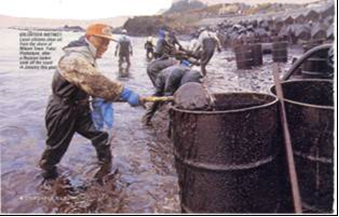
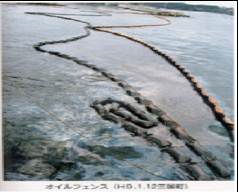
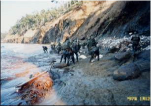
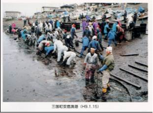
| [229] | Fire Department of Fukui Prefecture. (1998). Memories and Teaching on Oil-leakage Disaster of Russian Tanker. Committee of Disaster Record in Russian Tanker Oil-leakage Accidents. |
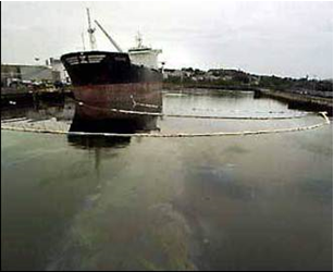
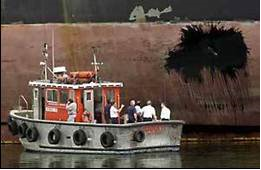
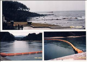
| [230] | Fleischer, C., Becker S., Eigenberger, G., 1996. Detailed modeling of the chemisorption of CO2 into NaOH in a bubble column, Chemical Engineering Science, 51, 1715-1724. |
| [231] | Fluent, Inc., 2001. Fluent 6.0 User’s Guide. Fluent, Inc., Lebanon, NH. Goring, D.G., Nikora, V.I., 2002. Despiking acoustic Doppler velocimeter data. Journal of Hydraulic Engineering 128 (1), 117-126. |
| [232] | F.S. de Sousa, N. Mangiavacchi, L.G. Nonato, A. Castelo, M.F. Tomé;, V.G. Ferreira, J.A. Cuminato, S. McKee, A front-tracking/front-capturing method for the simulation of 3d multi-fluid flows with free surfaces, J. Comput. Phys. 198 (2) (2004) 469–499. |
| [233] | F. S. Sousa, L. M. Portela, M. T. Kreutzer, C. R. Kleijn. Numerical simulation of slug flows in square hannels using a front-tracking/front-capturing method International Conference on Multiphase Flow, ICMF 2007, Leipzig, Germany. July 9 – 13, 2007. |
| [234] | Fu, X.Y., Ishii, M., 2003. Two-group interfacial area transport in vertical air–water flow I. Mechanistic model. Nuclear Engineering Design 219, 143–168. |
| [235] | Gachter, R., and B. Wehrli (1998), Ten years of artificial mixing and oxygenation: No effect on the internal phosphorus loading of two eutrophic lakes, Environ. Sci. Technol., 32(23), 3659-3665. |
| [236] | Ga¨chter, R., and B. Mu¨ ller (2003), Why the phosphorus retention of lakes does not necessarily depend on the oxygen supply to their sediment surface, Limnol. Oceanogr., 48(2), 929– 933. |
| [237] | G. Alendal, H. Drange, and F. Thorkildsen. Two-phase modeling of CO2 droplet plumes. Technical Report 153, Nansen Environmental and Remote Sensing Center, 1998. |
| [238] | García, C. M., and García, M. H. (2006). “Characterization of flow turbulence in large-scale bubble–plume experiments.” Exp. Fluids, 41(1), 91–101. |
| [239] | Garnier, A., Chavarie, C., Andre, G. and Klvana, D., 1990, The inverse fluidization airlift bioreactor, Chem Eng Comm, 98: 31. |
| [240] | Garrett, C., M. Li, and D. M. Farmer (2000), The connection between bubble size spectra and energy dissipation rates in the upper ocean, J. Phys. Oceanogr., 30, 2163–2171. |
| [241] | Gavrilescu,M. and Tudose, R. Z., 1997, Mixing studies in external-loop airlift reactors, Chem Eng J, 66: 97. |
| [242] | Gemza, A. (1995), Some practical aspects of whole lake mixing and hypolimnetic oxygenation: Ecological impacts of aeration on lakes and reservoirs in southern Ontario, Lake Reservoir Manage., 11(2), 141-142. |
| [243] | Georges L. Chahine. Strong interactions bubble/bubble and bubble/flow. 1994 Kluwer Academic Publishers. Printed in the Netherlnnds. Pp. 195-206. |
| [244] | G. K. Batchelor. Heat convection and buoyancy efiects in fluids. Quarterly Journal of The Royal Meteorological Society, 80:339-358, 1954. |
| [245] | Gibbons, H. L., (1994), Worlds largest attempt at hypolimnetic aeration, Lake Reservoir Manage., 9(2), 76. |
| [246] | G. L. Chahine, “Cloud cavitation: Theory,” Proceedings of the 14th Symposium on Naval Hydrodynamics, Ann Arbor, Michigan (National Academy Press, Washington D.C., 1983), pp. 161–195. |
| [247] | G. L. Chahine and R. Duraiswami, “Dynamical interactions in a multibubble cloud,” ASME J. Fluids Eng. 114, 680 (1992). |
| [248] | Glover, A., Skippon, S., and Boyle, R. (1995). Interferometric laser imaging for droplet sizing: a method for dropletsize measurement in sparse spray systems. Applied Optics, 34:8409–8421. |
| [249] | Goossens, L., 1979. Reservoir destratification with bubble plumes. Delft University Press. Delft, The Netherlands, 1979. EDB-80-118650 |
| [250] | Govier, G.w., and K. Aziz, 1972, The Flow of Complex Mixtures in Pipes. Van Nostrand Reinold Co. New York, 792 pp. |
| [251] | Goldsmith, H.L. and S.G. Mason (1962). The movement of single large bubbles in closed vertical tubes. J. Fluid. Mech. 14, 42-58. |
| [252] | Gong, X., Takagi, S., Matsumoto, Y., 2004. A Numerical Study on the Detailed Structure and Mass Transfer of Ozone Plumes for Water Purification System, Proceedings of the 5th International Conference on Multiphase Flow, May 30-June 4, Yokohama, Japan |
| [253] | Goosens L. H. J. and Smith J. M. 1975. The Hydrodynamics of Unconfined Bubble Columns for Mixing Lakes and Reservoirs. Chem. Eng. Tech. 47, 951. PP. 249-261. |
| [254] | G. P. Celata, M. Cumo, F. D’Annibale, and A. Tomiyama, Terminal bubble rising velocity in one-component systems, in Proc. of 39th European Two-Phase Flow Group Meeting, paper F-3 (Aveiro, 2001). |
| [255] | Gregory J. Orris and Michael Nicholas. Collective oscillations of fresh and salt water bubble plumes. 2000 Acoustical Society of America. [S0001-4966(99)03012-X] PACS numbers: 43.30.Nb, 43.30.Es {SAC-B}. J. Acoust. Soc. Am. 107 (2), February 2000. 771-787. |
| [256] | Grevet J.H., J. Szekely, N. El-Kaddah, An experimental and theoretical study of gas bubble driven circulation systems, Int. J. Heat Mass Transfer 25 (4) (1982) 487-497. |
| [257] | Griffith, P. And G.B. Wallis (1961). Two-phase slug flow. J. of Heat Transfer, Trans. ASME, Serie C 83, 307-320. |
| [258] | Gross R. W. and kuhlman J. M. 1992. Three-Component Velocity Measurements in a Turbulent Recarculating Bubble-Driven Liquid Flow. Int. J. Multiphase Flow 18(3), 413-421. |
| [259] | G. Tryggvason, B. Bunner, A. Esmaeeli, D. Juric, N. Al-Rawahi, W. Tauber, J. Han, S. Nas, and Y.-J. Jan. A Front-Tracking Method for the Computations of Multiphase Flow. Journal of Computational Physics 169, 708–759 (2001). |
| [260] | Guinot, V. (2001). “Numerical simulation of two-phase flow in pipes using Godunov method.” Int. J. Numer. Methods Eng., 50(5), 1169–1189. |
| [261] | Haberman, W. L. and Morton, R. K., "An Experimental Study of Bubbles Moving in Liquids," Trans ASCE Proc, Vol. 80, No. 387, Eng. Mech. Div., 1954. Soc. Civ. Eng., 80, 379-427. 2799, 227–252. |
| [262] | Hao, Y., and Prosperetti, A., 1999, “The Dynamics of Vapor Bubbles in Acoustic Pressure Fields,” Phys. Fluids, 11(8), pp. 2008–2019. |
| [263] | Hare, J. E., C. W. Fairall, W. R. McGillis, J. B. Edson, B. Ward, and R. Wanninkhof (2004), Evaluation of the National Oceanic and Atmospheric Administration / Coupled-Ocean Atmospheric Response Experiment (NOAA/COARE) air-sea gas transfer parameterization using GasEx data, J. Geophys. Res., 109, C08S11, doi:10.1029/2003JC001831. |
| [264] | Hasan, A.R., Kabir, C.S., 1992. Two-phase flow in vertical and inclined annuli. International Journal of Multiphase Flow 18 (2), 279–293. |
| [265] | Hassan Abdulmouti 2002. The Flow Patterns in Two Immiscible Stratified Liquids Induced by Bubble Plume. The International Journal of Fluid Dynamic. Vol. 6. Article 1. |
| [266] | Hassan Abdulmouti 2002. Visualization of The Flow Patterns in Two Immiscible Stratified Liquids Due to Bubble Plume. The 10th International Symposium on Flow Visualization. Kyoto Japan. August 26-29. |
| [267] | Hassan Abdulmouti 2003. Visualization and Image Measurement of Flow Structures Induced by a Bubbly Plume. Ph. D. thesis. Fukui University. |
| [268] | Hassan Abdulmouti 2006. Bubbling Convection Patterns in Immiscible Two-phase Stratified Liquids. International Journal of Heat Exchangers (IJHEX). Vol. VII. No. 1. Pp. 123-143. ISSN 1524-5608. June 2006. |
| [269] | Hassan Abdulmouti. Surface Flow Generation Mechanism Induced by Bubble Plume. Yanbu Journal of Engineering and Science (YJES). Second issue. PS-M02-28 (50-67). 2011. |
| [270] | Hassan Abdulmouti. The Principle of Bubbly Flow and Its Application Especially to Oil Fence. Alzahrawi Encyclopedia for Arab Engineer. 1, 11, 2012. |
| [271] | Hassan Abdulmouti. The Principle and Classification of PIV. Alzahrawi Encyclopedia for Arab Engineer. 19, 9, 2012. |
| [272] | Hassan Abdulmouti. Particle Imaging Velocimetry (PIV) Technique: Principles and Application. Yanbu Journal of Engineering and Science (YJES). ISSN: 1658-5321. Vol. 6, April 2013. |
| [273] | Hassan Abdulmouti. Particle Imaging Velocimetry (PIV) Technique: Principles, the typically used methods, classification and applications. Scholar's Press. ISBN-13: 978-3-639-51249-6. 6 March, 2013. |
| [274] | Hassan Abdulmouti. Measurement of Flow Structures Induced by a Bubbly Plume Using Visualization, PIV and Image Measurement. Scholar's Press. ISBN-13: 978-3-639-51490-2. 7, June, 2013. |
| [275] | Hassan Abdulmouti. Bubbly Two-Phase Flow: Part I- Characteristics, Structures, Behaviors and Flow Patterns. DOI: 10.5923/j.ajfd.20140404.03. American Journal of Fluid Dynamics. Scientific and Academic Publishing. Volume 4, Number 4, 4(4): 194-240. December 2014. |
| [276] | Hassan Abdulmouti. Bubbly Two-Phase Flow: Part II- Characteristics and Parameters. DOI: 10.5923/j.ajfd.20140404.01 American Journal of Fluid Dynamics. Scientific and Academic Publishing. Volume 4, Number 4, 4(4): 115-180. December 2014. |
| [277] | Hassan Abdulmouti. Parameter Measurements of Bubble Plume Structure. 19th Australasian Fluid Mechanics Conference. Melbourne, Australia. 8-11 December 2014. |
| [278] | Hassan Abdulmouti. The Role of Kaizen (Continuous Improvement) in improving Companies’ Performance: A Case Study. ISBN: 978-1-4799-6064-4. INSPEC Accession Number: 15091284. DOI: 10.1109/IEOM.2015.7093768. May 2015. IEEE Xplore Digital Library. |
| [279] | Hassan Abdulmouti. Experimental Measurement for Surface Flow Characteristics Generated by a Bubble Plume. The Journal of Flow Visualization and Image Processing. 22 (1–3), 39–58. 2015. Begell House “USA”. The Home for Science and Engineering. |
| [280] | Hassan Abdulmouti. Experimental Measurements of Bubble Convection Models in Two-phase Stratified Liquids. Experimental Thermal and Fluid Science (2016). Volume 83C, May 2017. Pages 69-77. (ELSEVIER). https://doi.org/10.1016/j.expthermflusci.2016.12.010. |
| [281] | Hassan Abdulmouti. 2D- numerical simulation of surface flow velocity and internal flow structure generated by bubbles. Multiphase Science and Technology 28 (2): 153–171 (2016). 0276–1459/16/$35.00 © 2016 by Begell House, Inc “USA”. The Home for Science and Engineering. DOI: 10.1615/MultScienTechn.2017018926. |
| [282] | Hassan Abdulmouti. The Measurements of Bubble Plume Structure Parameter. International Journal of Fluid Mechanics Research. Volume 44. Issue 4. pages 277-295. (2017). Begell House “USA”. The Home for Science and Engineering. DOI: 10.1615/InterJFluidMechRes.2017014476. |
| [283] | Hassan Abdulmouti. Numerical Simulation and Fundamental Characteristics of Surface Flow Generated by Bubbly Flows. International Journal of Fluid Mechanics Research. Volume 45, Issue 3, Pp. 263-282. (2018). ISSN Print: 1064-2277. ISSN Online: 2152-5102. DOI: 10.1615/InterJFluidMechRes.2018021875. Begell House “USA”. The Home for Science and Engineering. |
| [284] | Hassan Abdulmouti. Measurements of Thermal Effect on Bubble Parameter. The 3rd Thermal and Fluids Engineering Conference (TFEC). March 4-7, 2018. Fort Lauderdale, FL, USA. |
| [285] | Hassan Abdulmouti. Numerical Simulation of Bubble Convection in Two-phase Stratified Liquids" Multiphase Science and Technology by Begell House, Inc “USA”. Volume 31, Issue 2, pp. 133–149 (2019). The Home for Science and Engineering. DOI: 10.1615/MultScienTechn.2019029995. (Impact factor: 0.82, SJR:0.153- Q3= 0.184, H Index: 16, SINP 0.222, Cite Score 0.26). |
| [286] | Hassan Abdulmouti. Measurement of Bubbles Properties to Generated Efficient Surface Flow. The 4th International Conference on Multiphase Flow and Heat Transfer (ICMFHT'19). April 10-12, 2019. Rome, Italy. |
| [287] | Hassan Abdulmouti. Effect of Temperature on Surface Flow Generated by Bubble Plumes. The Journal of Flow Visualization and Image Processing. Vol. 29, Issue 1, Pp. 1-28. 2022. Begell House “USA”. The Home for Science and Engineering. (Impact factor: 0.321, SJR: Q3= 0.214, H Index: 12). ISSN Print: 1065-3090, ISSN Online: 1940-4336; SNIP: 0.312. DOI: 10.1615/JFlowVisImageProc.2021038705. |
| [288] | Abdulmouti, Hassan. 2021. "Improving the Performance of Surface Flow Generated by Bubble Plumes" MDPI. Fluids. Vol: 6, No. 8: 262. https://doi.org/10.3390/fluids6080262. Special Issue "Dynamics of Droplets and Bubbles". Multidisciplinary Digital Publishing Institute. (Impact factor: 1.81, SJR: Q2= 0.399, H Index: 14). |
| [289] | Abdulmouti, Hassan. "SURFACE FLOW GENERATION MECHANISM INDUCED BY A BUBBLE PLUME." Yanbu Journal of Engineering and Science 2.1 (2021): 50-67. |
| [290] | Hassan Abdulmouti, Esam Jassim. Visualization and Measurements of Bubbly Two-Phase Flow Structure Using Particle Imaging Velocimetry (PIV). Annual International Interdisciplinary Conference, IIC. Azores, Portugal. 24 -26 April 2013. |
| [291] | Hassan Abdulmouti and Tamer Mohamed Mansour. The Technique of PIV and Its Applications. 10th International Congress on Liquid Atomization and Spray Systems (ICLASS-2006). Aug. 27-Sept. 1. Kyoto, Japan. 2006. |
| [292] | Hassan Abdulmouti and Tamer Mohamed Mansour. Bubbly Two-Phase Flow and Its Application. 10th International Congress on Liquid Atomization and Spray Systems (ICLASS-2006). Aug. 27-Sept. 1. Kyoto, Japan. 2006. |
| [293] | Hassan Abdulmouti, Fujio Yamamoto, Yuichi Murai, Yasuhiro Kobayashi, 1997. Research and Development for a New Bubble Curtain Type of Oil Fence. Journal of the Visualization Society of Japan. vol. 17 suppl. No. 1. Pp. 239~242. |
| [294] | Hassan Abdulmouti, Yuichi Murai, junichi Ohat, Fujio Yamamoto 1998. PIV Measurement and Numerical Analysis of Flow around Bubble Curtain published in preprint of (J.S.M.E.) Japanese Society of Mechanical Engineer. No. 987-1. pp. 83~84. |
| [295] | Hassan Abdulmouti, Yuichi Murai, junichi Ohat, Fujio Yamamoto 1999. PIV Measurement of Surface Flow Induced by Bubble Curtain. Journal of the Visualization Society of Japan. Vol. 19 Suppl. No. 1. Pp.239~242. |
| [296] | Hassan Abdulmouti, Yuichi Murai, junichi Ohat, Fujio Yamamoto 1999. PIV Measurement of Bubbly Flow Interaction with Water Surface. Journal of the Visualization Society of Japan. Vol. 19. Suppl. No. 2. Pp.209-210. |
| [297] | Hassan Abdulmouti Yuichi Murai, Ohno Yasushi, Fujio Yamamoto 2001. Measurement of Bubble Plume Generated Surface Flow Using PIV, Journal of the Visualization Society of Japan. Vol. 21. No. 2. Pp. 31-37. |
| [298] | Hassan Abdulmouti and Monsif Shinneeb. Investigation of Free-Surface Flow Induced by a Bubbly Plume Using PIV. 2020 (ASET). Electronic ISBN: 978-1-7281-4640-9. ISBN: 978-1-7281-4641-6. Print on Demand (PoD). Pp. 1-5. DOI: 10.1109/ASET48392.2020.9118203. Publisher: IEEE. Added to IEEE Xplore: 16 June 2020. |
| [299] | Hassan Abdulmouti and Monsif Shinneeb. Investigation of Free-Surface Flow Induced by a Bubbly Plume Using PIV. The International Conference on Sustainable Environment and Urban Infrastructure (SEUI-2020 ASET). Advances in Science and Engineering Technology International Conferences. February 04-06, 2020. |
| [300] | Hassan, Y. A., Blanchat, T. K., Seeley, Jr., C. H. and Canaan, R. E. 1992 Simultaneous velocity measurements of both components of a two-phase flow using particle image velocimetry. Intl J. Multiph. Flow 18 (3), 371–395. |
| [301] | Hassoon, H. 1989. A two-phase investigation relating to circulating bubble absorbers. PhD thesis, Mechanical Engineering Department, University of Bristol, U.K. |
| [302] | Herold, K.E.; Radermacher, R. and Klein, S.A. 1996. Absorption Chillers and Heat Pumps. CRC Press, Boca Raton, FL. |
| [303] | Henderson D. M. and Miles J. W. 1994. Surface-Wave Damping in Circular Cylinder with a Fixed Contact Line. J. Fluid Mech. 275, 285-299 (hereinafter reefed to as HM94). |
| [304] | Herringe, R.A., and Davis, M.R., Journal of Fluid Mechanics, 73 (1976), 97. |
| [305] | Hess, C. F. (1998). Planar particle image analyzer. In 9th International Symposium on Applications of Laser Techniques to Fluid Mechanics, Lisbon. |
| [306] | Hibiki, T., and Ishii, M., 1999, “Experimental Study on Interfacial Area Transport in Bubbly Two-Phase Flows,” Int. J. Heat Mass Transfer, 42, pp. 3019– 3035. |
| [307] | Hideki Murakawa, Hiroshige Kikura, Masanori Aritomi. Application of Multi-Wave Tdx For Multi-Phase Flow Measurement. 4th International Symposium on Ultrasonic Doppler Method for Fluid Mechanics and Fluid Engineering Sapporo, 6.-8. September, 2004. |
| [308] | Higson, D.J., 1960, The Flow of Gas-Liquid Mixtures in vertical Pipes. Thesis, Imperial College of Science and Technology, England. |
| [309] | Hjalmars, S., 1973, "The origin of Instability in Airlift Pumps," Journal of Applied Mechanics, June 1973, pp. 399-404. |
| [310] | H. Karimi, M. R. Rahimi, “A Robust Classification method for the Prediction of Two-phase Flow Pattern, using Ensemble Classifiers Technique,” in proc. 11th Int. Conf. on Multiphase Flow in Industrial Plants, Palermo, 2008, pp. 443-451. |
| [311] | Hondzo, M. (1998), Dissolved oxygen transfer at the sediment-water interface in a turbulent flow, Water Resour. Res., 34(12), 3525-3533. |
| [312] | Hoult D. P. Oil on the Sea. Plenum, 1969. |
| [313] | Hovland M, Judd AG, Burke RA Jr (1993.) The global flux of methane from shallow submarine sediments. Chemosphere 26:559–578. |
| [314] | Howell D., Heath T., Mckenna C., Hwang W. and Schatz M. F. 2000. Measurements of Surface-Wave Damping in a Container. Phys. Fluids 12, 322-326. |
| [315] | Huang, F., Takahashi, M., and Guo, L. (2005). “Pressurewave propagation in air-water bubbly and slug flow.” Prog. Nucl. Energy, 47(1-4), 648–655. |
| [316] | Hubert Chanson. Air-Water Bubbly Flows: Theory and Applications. Ph. d. thesis. School of Engineering. The University of Queensland. January 1999. |
| [317] | Hu, H. H. 1996 Direct simulation of flows of liquid-solid mixtures. Intl J. Multiphase Flow 22, 335-352. |
| [318] | Hui Zhu, Mark Simmons, Waldek Bujalski and Alvin Nienow. Mixing of the Liquid Phase in a Model Aerated Bioreactor Equipped with ‘Elephant Ear’ Agitators using Particle Image Velocimetry. International Conference on Multiphase Flow, ICMF 2007, Leipzig, Germany, July 9–13, 2007. |
| [319] | Husain, L.A., and P.L. Spedding, 1976, "The Theory of the Gas-Lift Pump," International Journal of Multiphase Flow, Vol. 3, pp. 83-87. |
| [320] | Hussain N. A. and Siegel R. 1976. Liquid Jet Pumped by Rising Gas Bubbles, J. Fluids Eng., March 8. Pp. 49-62. |
| [321] | Hussain N. A. and Narang B. S. 1984. Simplified Analysis of Air-Bubble Plumes in Moderately Stratified Environments. ASME. Journal of Heat Transfer. Vol. 106, pp. 543-551. |
| [322] | H. Wang, Z.-Y. Zhang, Y.-M. Yang, and H. S. Zhang, Surface tension effects on the behavior of a rising bubble driven by buoyancy force. Chin. Phys. B 19, 026801 (2010). |
| [323] | Hyun Dong Kim, Seung Jae Yi, Jong Wook Kim and Kyung Chun Kim. Structure analysis of bubble driven flow by time-resolved PIV and POD techniques. Journal of Mechanical Science and Technology 24 (4) (2010) 977~982. DOI 10.1007/s12206-010-0210-1. |
| [324] | Iamandi, C., and Rouse, H. (1969) “Jet-induced circulation and diffusion.” J. Hydr. Div., 95(2), 589–601. |
| [325] | Ibrahim, Y. A. A., Briens, C. L., Margaritis, A. and Bergongnou,M. A., 1996, Hydrodynamic characteristics of a three-phase inverse fluidizedbed column, AIChE J, 42: 1889. |
| [326] | Iguchi, M., Takeuchi, H. and Morita, Z. (1991) The Flow Field in Air-Water Vertical Bubbling Jets in a Cylindrical Vessel. ISIJ International, 31 (3), 246-253, 1991. |
| [327] | Iguchi, M., Uemura, T., Yamamoto, F., Morita, Z., 1992. Multiphase flows in ironmaking and steel-making processes. Jpn J. Multiphase Flow 6, 54–64. |
| [328] | Iguchi, M., Kondoh, T., Morita, Z., Nakajima, K., Hanazaki, K., Uemura, T. and Yamamoto, F. (1995) Velocity and Turbulence Measurements in a Cylindrical Bath Subject to Central Bottom Gas Injection. Metallurgical and Material Transactions B, 26B, 241-247, 1995. |
| [329] | Iguchi, M., Shinkawa, M., Nakamura, H. and Morita, Z. (1995) Mean Velocity and Turbulence of Water Flow in a Cylindrical Vessel Agitated by Bottom Air Injection. ISIJ International, 35 (12), 1431-1437, 1995. |
| [330] | Iguchi M., Okita K., Nakatani T., Kasai N. 1997. Structure of Turbulent Round Bubbling Jet Generated by Premixed Gas and Liquid Injection, Int. J. Multiphase Flow, Vol. 23, 2, pp.249-262. |
| [331] | Ihab Edward Gerges. Two-Phase Bubbly Flow Structure In Large Diameter Pipes. Master of Engineering Thesis. Cairo University). March, 1999. ISBN. 3 9005 0219 9807 9. |
| [332] | Imberger, J., and Patterson, J. C. (1990). "Physical limnology." Advances in applied mechanics, 27, 305-475. |
| [333] | Imteaz, M. A., and T. Asaeda (2000), Artificial mixing of lake water by bubble plume and effects of bubbling operations on algal bloom, Water Res., 34(6), 1919-1929. |
| [334] | Ishii, M., 1975. Thermo-Fluid Dynamic Theory of Two-Phase Flow. Eyrolles, Paris. |
| [335] | Ishii, M., Mishima, K., 1984. Two-fluid model and hydrodynamic constitutive relations. Nuclear Engineering and Design 82, 107–126. |
| [336] | Ishii, M. and Sun, X. Interfacial Characteristics of Two-phase Flow. Multiphase Science and Technology, Vol. 18, 1-29 (2006). |
| [337] | Jakobsen, H. A., Sannaes, B. H., Grevskott, S., and Svendsen, H. F. (1997). Modeling of vertical bubble-driven flows. Industrial and Engineering Chemistry Research, 36, 4052. |
| [338] | Jacobsen, H.A., 2008. Chemical reactor modeling. Springer-Verlag, Berlin. |
| [339] | Jaeger, D. (1990), TIBEAN: A new hypolimnetic water aeration plant, Internat. Vereinigung fuer Theoret. und Angewandte Limnol., 24(1), 184-187. |
| [340] | Jameson, G. J., and Kupferberg, A. (1967). Pressure behind a bubble accelerating from rest: Single theory and applications. Chemical Engineering Science, 22, 1053-1055. |
| [341] | Jaromír Havlica, Miroslav Šimčík, Radovan Bunganič, Marek Večeř, Marek Ruzicka, Kamil Wichterle, Jiří Drahoš. A case study on bubble formation: numerics vs. measurements. International Conference on Multiphase Flow, ICMF 2007, Leipzig, Germany, July 9 – 13, 2007. |
| [342] | J. Chahed, V. Roig, L. Masbernat. Eulerian–Eulerian two-fluid model for turbulent gas–liquid bubbly flows. International Journal of Multiphase Flow 29 (2003) 23–49. |
| [343] | Jeelani, S.A.K., K.V. KasipatiRao, and G.R. Balasubramanian, 1979, "The Theory of the Gas-Lift Pump: A Rejoinder," International Journal of MuItiphase Flow, Vol. 5, pp. 225-228. |
| [344] | Jeff Tyson. howstuffworks.com. Facweb.cs.depaul.edu. 2021. How Inkjet Printers Work. [online] Available at:http://facweb.cs.depaul.edu/sgrais/how_inkjet_printers_work.htm. |
| [345] | Jenkins A. D. and Dysthe K. B. 1997. The Effective Film Viscosity Coefficients of a Thin Floating Fluid Layer. J. Fluid Mech. 344, 335-337. |
| [346] | Jennifer Ann Caulfield. Environmental impacts of carbon dioxide ocean disposal: Plume predictions and time dependent organism experience. Master's thesis, Massachusetts Institute of Technology, Department of Civil and Environmental Engineering, 1996. |
| [347] | Jennifer A. Caulfield, E. Eric Adams, David I. Auerbach, and Howard J. Herzog. Impacts of ocean CO2 disposal on marine life: II. Probabilistic plume exposure model used with a time varying dose-response analysis. Environmental Modeling and Assessment 2, pages 345-353, 1997. |
| [348] | J. Hua and J. Lou. Numerical simulation of bubble rising in viscous liquid. J. Comput. Phys., 222(2): 769–795, 2007. |
| [349] | Jiacai Lu and Gretar Tryggvason. Numerical study of turbulent bubbly downflows in a vertical channel. PHYSICS OF FLUIDS 18, 103302 (2006). American Institute of Physics. (DOI: 10.1063/1.2353399). |
| [350] | Jiˇrí Kˇrišt’ál, Jaromír Havlica and Vladimír Jiˇriˇcný. Flow Patterns and Void Fraction in Thin-Gap Channel. International Conference on Multiphase Flow, ICMF 2007, Leipzig, Germany, July 9–13, 2007. |
| [351] | Jirka, G., and Harleman, D. R. F. (1979). “Stability and mixing of a vertical plane buoyant jet in confined depth.” J. Fluid Mech., 94, 275–304. |
| [352] | Johansen, S. T., Robertson, D. G. C., Woje, K. and Engh, T. A. (1988) Fluid-Dynamics in Bubble Stirred Ladles: Part I. Experiments. Metallurgical Transactions B, 19B, 745-754, 1988. |
| [353] | Johansen, S. T. and Boysan, F. (1988) Fluid-Dynamics in Bubble-Stirred Ladles: Part II. Mathematical Modelling. Metallurgical Transactions B, 19B, 755-764, 1988. |
| [354] | Johansen, O. (2000), DeepBlow - a Lagrangian plume model for deep water blowouts, Spill Sci. and Tech. Bull., 6(2), 103-111. |
| [355] | Johnson, B. D., and R. C. Cooke (1979), Bubble populations and spectra in coastal waters: A photographic approach, J. Geophys. Res., 84(C7), 3761–3766, doi: 10.1029/JC084iC07p03761. |
| [356] | Johnson G, Hornewer N, Robertson D, Olson D, Gioja J (2000) Methodology, Data Collection, and Data Analysis For Determination of Water-Mixing Patterns Induced by Aerators And Mixers. Water Resources Investigation Report 00-4101. 48 pp, U.S. Geological Survey. |
| [357] | J. Magnaudet and I. Eames, The motion of high-Reynolds-number bubbles in inhomogeneous flows, Ann. Rev. Fluid Mech. 32, 659 (2000). |
| [358] | John C. Patterson and J¨org Imberger. Simulation of bubble plume destratification systems in reservoirs. Aquatic Sciences, 51(1):1 - 18, 1989. |
| [359] | Jones W. T. 1972. Air Barriers as Oil-Spill Containment Devices. Society of Petroleum Engineers Journal, pages 126-142, April 1972. |
| [360] | Jordan F. Clark, Ira Leifer, Libe Washburn, Bruce P. Luyendyk Compositional changes in natural gas bubble plumes: observations from the Coal Oil Point marine hydrocarbon seep field. Geo-Mar Lett (2003) 23: 187–193 DOI 10.1007/s00367-003-0137-y. |
| [361] | Jose A. Nicolas and Jose M. Vega. 2000. A Note on the Effect of Surface Contamination in Water Wave Damping. J. Fluid Mech. 2000. Vol. 410. Pp. 367-373. Cambridge University Press. United Kingdom. |
| [362] | Joshi J, Vitankar V, Kulkarni A, Dhotre M, Ekambara K (2002) Coherent flow structures in bubble column reactors. Chem Eng Sci 57:3157–3183. |
| [363] | Josiam, R. M., and H. G. Stefan (1999), Effect of flow velocity on sediment oxygen demand: comparison of theory and experiments, J. Am. Water Resour. Assoc., 35, 433-439. |
| [364] | Kouremenos, D.A., and J. Staicos, 1985, "Performance of a Small Air-lift Pump," International Journal of Heat Fluid Flow. Vol. 6, No.3, pp. 217-222 |
| [365] | J. Rubinstein, “Bubble interaction effects on waves in bubbly liquids,” J. Acoust. Soc. Am. 77, 2061 (1985). |
| [366] | J. S. Turner. Turbulent entrainment: the development of the entrainment assumption, and its application to geophysical flows. Journal of Fluid Mechanics, 173:431-471, 1986. |
| [367] | Judd AG, Davies G, Wilson J, Holmes R, Baron G, Bryden I (1997) Contributions to atmospheric methane by natural seepages on the U.K. continental shelf. Mar Geol 140:427–455. |
| [368] | Judd AG, Hovland M, Dimitrov LI, Garcia-Gil S, Jukes V (2002). The geological methane budget at continental margins and its influence on climate change. Geofluids 2: 109–126. |
| [369] | Judd, R.L.; Hwang, K.S.: A Comprehensive Model for Nucleate Boiling Heat Transfer Including Microlayer |
| [370] | Evaporation. Journal of Heat Transfer, 98, 623-629 (1976). |
| [371] | Jung Hee Seo, Sanjiva K. Lele, and Gretar Tryggvason. Investigation and modeling of bubble-bubble interaction effect in homogeneous bubbly flows. PHYSICS OF FLUIDS 22, 063302 (2010). |
| [372] | Jun-Hong Liang, James C. McWilliams, Peter P. Sullivan, and Burkard Baschek. Large eddy simulation of the bubbly ocean: New insights on subsurface bubble distribution and bubble-mediated gas transfer. Journal of Geophysical Research, Vol. 117, C04002, doi:10.1029/2011JC007766, 2012 |
| [373] | J. W. A. De Swart and R. Krishna, Effect of particles concentration on the hydrodynamics of bubble column slurry reactors, Chem. Eng. Res. Design, Trans. Ind. Chem. Eng. 73, 308 (1995). |
| [374] | K. A. Shollenberger, J. R. Torczynski, D. R. Adkins, T. J. O’Hem, and N. B. Jackson, Gamma-densitometry tomography of gas holdup spatial distribution in industrial scale bubble columns, Chem. Eng. Sci. 52, 2037 (1997). |
| [375] | Kawase, Y., and Ulbrecht, J. J. (1981). Formation of drops and bubbles in flowing liquids. Industrial and Engineering Chemistry, Process Design and Development, 20(4), 636-640. |
| [376] | Kelessidis, V.C., Dukler, A.E., 1989. Modeling flow pattern transitions for upward gas–liquid flow in vertical concentric and eccentric annuli. International Journal of Multiphase Flow 15 (2), 173–191. |
| [377] | Kenji Uchida, Keita Kosuge, Atsuhide Kitagawa and Yoshimichi Hagiwara. Heat transfer enhancement for water natural convection along a vertical plate by micro-bubbles. International Conference on Multiphase Flow, ICMF 2007, Leipzig, Germany, July 9–13, 2007. |
| [378] | Kim, I., Kamotani, Y., and Ostrach, S. (1994). Modeling bubble and drop formation in flowing liquids in microgravity. AIChE Journal, 40(1), 19-28. |
| [379] | Lim, Kang Yuan; Quinto-Su, Pedro A.; Klaseboer, Evert; Khoo, Boo Cheong; Venugopalan, Vasan; Ohl, Claus-Dieter. Nonspherical laser-induced cavitation bubbles. Physical Review E, vol. 81, Issue 1, id. 016308. Pub Date: January 2010. DOI: 10.1103/PhysRevE.81.016308 https://www.science.gov/topicpages/l/laser-induced+cavitation+bubble. |
| [380] | Klas Cederwall and John D. Ditmars. Analysis of Air-Bubble Plumes. Report No. KH-R-24. September 1970. California Institute of Technology, Pasadena, CA, 1970. |
| [381] | Kodama, Y. Kakugawa, A., Takahashi, T., Kawashima; H., Experimental Study on Microbubbles and their Applicability to Ships for Skin Friction Reduction, International Journal of Heat and Fluid Flow, Vol.21, Issue 5 (2000) p.582. |
| [382] | Kodama, Takahashi, Hori, Makino, and Ueda, 3rd Int. Symp. on Two-Phase Flow Modelling and Experimentation, Pisa (2004). |
| [383] | Kodama, Y. Kakugawa, A., Takahashi, T., Kawashima; H.A Full-Scale Air Lubrication Experiment Using a Large Cement Carrier for Energy Saving (Result and Analysis), Conference Proceedings, the Japan Society of Naval Architects and Ocean Engineers, Vol.6 (2008) p.163. |
| [384] | Koenig, G., Anders, K., and Frohn, A. (1986). A new light scattering technique to measure the diameter of periodically generated moving droplets. Journal of Aerosol Sciences, 17:157–167. |
| [385] | Kortmann, R. W., Knoecklein G. W., Bonnell., H. C., (1994), Aeration of stratified lakes: Theory and practice, Lake Reservoir Manage., 8(2), 99-120. |
| [386] | Kortmann, R. W. (1994), Oligotrophication of Lake Shenipsit by layer aeration, Lake Reservoir Manage., 9(1), 94-97. |
| [387] | Kreshimir Zic, Hienz G. Stefan. Destratification Induced by Bubble Plumes. Water Quality Research Program. Technical Report W-94-3. June 1994. |
| [388] | Krepper, E., Weiss, F. -., Alt, S., Kratzsch, A., Renger, S. and Kästner, W. (2011), "Influence of air entrainment on the liquid flow field caused by a plunging jet and consequences for fibre deposition", Nuclear Engineering and Design, vol. 241, no. 4, pp. 1047-1054. |
| [389] | Kreutzer, M., T., Heiszwolf, J., J. and Moulijn, J., A., AIChE Journal, 51, 9, 2428-2440 (2005). |
| [390] | Kreutzer, M. T. Kapteijn, F. Moulijn J. A. and Heiszwolf J. J.. Chem. Eng. Science, Vol. 60, 5895–5916, 2005. |
| [391] | Krishna, R. and van Baten, J.M., 1998. Simulating the motion of gas bubbles in a liquid. Nature, 398, p. 208. |
| [392] | Krishna, R. and Sie, S.T., 2000. Design and scale-up of the Fischer-Tropsch bubble column slurry reactor. Fuel Proc. Tech., 64, pp. 73-105. |
| [393] | Kristian Etienne Einarsrud and Iver Brevik. KINETIC Energy Approach To Dissolving Axisymmetric Multiphase Plumes. arXiv.org. physics. arXiv: 0804.2789v1. April 17, 2008. |
| [394] | Kvenvolden KA (1993) Gas hydrates—geological perspective and global change. Rev Geophys 31:173–187. |
| [395] | Kvenvolden KA (1995) A review of the geochemistry of methane in natural gas hydrate. Org Geochem 23:997–1008. |
| [396] | Kvenvolden KA, Lorenson TD, Reeburgh WS (2001) Attention turns to naturally occurring methane seeps. EOS 82: 457. |
| [397] | Kubasch, J. H. 2001 Bubble hydrodynamics in large pools. Doctoral dissertation, ETH No. 14398, Zurich, Switzerland. |
| [398] | Kuhn de Chizelle, Y., Ceccio, S. L., and Brennen, C. E., 1995, “Observations and Scaling of Traveling Bubble Cavitation,” J. Fluid Mech., 293, pp. 99–126. |
| [399] | Kupferberg, A., and Jameson, G. J. (1970). Pressure fluctuations in a bubbling system with special reference to sieve plates. Transactions of the Institution of Chemical Engineers, 48, T140-T150. |
| [400] | Kuwagi, K. and Ozoe, H. (1999) Three-Dimensional Oscillation of Bubbly Flow in a Vertical Cylinder. International Journal of Multiphase Flow, 25, 175-182, 1999. |
| [401] | Lamarre, E., and W. K. Melville (1991), Air entrainment and dissipation in breaking waves, Nature, 351, 469–472. |
| [402] | Lance, M. and Bataille J., 1991, Turbulence in the Liquid-phase of a uniform bubbly air water-flow. Journal of Fluid Mechanics, 222, Pp.95-118. |
| [403] | Lance, M., Marrie, J.L., Bataille, J., 1991. Homogeneous turbulence in bubbly flows. J. Fluids Eng. 113, 295–300. |
| [404] | Lapin, A., and LuK bbert, A. (1994). Numerical simulation of the dynamics of two-phase gas-liquid flows in bubble columns. Chemical Engineering Science, 49(21), 3661. |
| [405] | Laureshen, C. J., and R. D. Rowe (1987), Modeling of plane bubble plumes, paper presented at 24th National Heat Transfer Conference and Exhibition, Am. Soc. Mech. Engineers, Pittsburgh, PA, 9-12 Aug. |
| [406] | Leah Sarah Reingold. An experimental comparison of bubble and sediment plumes in stratified environments. Master's thesis, Massachusetts Institute of Technology, Department of Civil and Environmental Engineering, 1994. |
| [407] | L. D’Agostino, C. E. Brennen, and A. Acosta, “Linearized dynamics of two dimensional bubbly and cavitating flows over slender surfaces,” J. Fluid Mech. 192, 485 (1988). |
| [408] | L. D’Agostino and C. E. Brennen, “Linearized dynamics of spherical bubble clouds,” J. Fluid Mech. 199, 155 (1989). |
| [409] | Lehman, J. and Hammer, J., (1978), Continuous fermentation in tower fermentor, I European congress on biotechnology, Interlaken, Part 1, 1. |
| [410] | Leitch, A.M., and Baines, W. D. 1989. Liquid Volume Flux in a Weak Bubble Plume, J. Fluid Mech., Vol. 205. Pp. 77-90. |
| [411] | Leitch, A. M., and Baines, W. D. (1989). “Measurement of liquid volume flux in a bubble plume.” J. Fluid Mech., 205, 77–98. |
| [412] | Leifer I, Clark JF (2002) Modeling trace gases in hydrocarbon seep bubbles: application to marine hydrocarbon seeps in the Santa Barbara Channel. Russian Geol Geophys 47:572–579. |
| [413] | Leifer I, Patro RK (2002) The bubble mechanism for methane transport from the shallow sea bed to the surface: a review and sensitivity study. Cont Shelf Res 22: 2409–2428. |
| [414] | Leifer I, Clark JF, Chen RF (2000) Modifications of the local environment by natural marine hydrocarbon seeps. Geophys Res Lett 27:3711–3714. 192 |
| [415] | Legile, P., Menard, G., Laurent, C., Thomas, D. and Bernis, A., 1992, Contribution to the study of an inverse three-phase fluidized bed operating countercurrently, Int Chem Eng, 32: 41. |
| [416] | Lemckert, C. J., and Imberger, J. (1993). “Energetic bubble plumes in arbitrary stratification.” J. Hydraul. Eng., 119(6), 680–703. |
| [417] | Leon, Arturo S., Ghidaoui, M. S., Schmidt, A. R., and Garcia, M. H. (2008). “Efficient second-order accurate shock-capturing scheme for modeling one-and two-phase water hammer flows.” J. Hydraul. Eng., 134(7), 970–983. |
| [418] | L. E. Rincón, F. A. Bombardelli and M. H. García. Experimental Evidence for Scaling Laws in Bubble Plumes.World Water Congress 2004. |
| [419] | Levich V. G. (1962). Physicochemical Hydrodynamics, Section 87, Prentice Hall, Engelwood Cliffs, N.J. |
| [420] | Liang, J.-H., J. C. McWilliams, P. P. Sullivan, and B. Baschek (2011), Modeling bubbles and dissolved gases in the ocean, J. Geophys. Res., 116, C03015, doi:10.1029/2010JC006579. |
| [421] | Lima Neto, Iran & David, Zhu & Rajaratnam, N. (2008). Bubbly jets in stagnant water. International Journal of Multiphase Flow. 34. 1130-1141. 10.1016/j.ijmultiphaseflow.2008.06.005. |
| [422] | Lindenschmidt, K. E., and P. F. Hamblin (1997), Hypolimnetic aeration in Lake Tegel, Berlin, Water Res., 31(7), 1619-1628. |
| [423] | Lin, T. J. and Donnelly, H. G. (1966), "Gas bubble entrainment by plunging laminar liquid jets", AICHE Journal, vol. 12, no. 3, pp. 563-571. |
| [424] | Liu, T.J., Bankoff, S.G., 1990. Structure of air-water bubbly flow in a vertical pipe: I-Liquid mean velocity and turbulence measurements. Int. J. Heat Mass Transfer 36 (4), 1049–1060. |
| [425] | Little, J. C. (1995), Hypolimnetic aerators: Predicting oxygen transfer and hydrodynamics, Water Res., 29(11), 2475-2482. |
| [426] | Little, J. C., and D. F. McGinnis (2001), Hypolimnetic oxygenation: Predicting performance using a discrete-bubble model, Water Science and Technology: Water Supply, 1(4), 185- 191. |
| [427] | Liu, T.J., and S. G. Bankoff, “Structure of air-water bubbly flow in a vertical pipe. Part 2: Void fraction, bubble velocity and bubble size distribution,” Int. J. Heat Mass Transfer 36, 1061 (1993). |
| [428] | Liu, T.J., and S. G. Bankoff, “Structure of air water bubbly flow in a vertical pipe. Part I: Liquid mean velocity and turbulence measurements,” Int. J. Heat Mass Transfer 36, 1049 (1993). |
| [429] | Liu, T. J., and Bankoff, S. G., 1993, “Structure of Air-Water Bubbly Flow in a Vertical Pipe- I,” Int. J. Heat Mass Transfer, 36, pp. 1049–1060. |
| [430] | Liu, T. J., and Bankoff, S. G., 1993, “Structure of Air-Water Bubbly Flow in a Vertical Pipe- II,” Int. J. Heat Mass Transfer, 36, pp. 1061–1072. |
| [431] | Liu, T.J., Wang, S.J., 2001. Optimization of local and area-averaged interfacial area concentration correlations in two-phase bubbly flow. In: Proceedings of Fourth International Conference on Multiphase Flow, New Orleans, USA. |
| [432] | Lockhart, R.W. and Martinelli, R.C. 1949. Proposed correlation of data for isothermal two-phase, two-component flow in pipes. Chem. Eng. Prog., Vol. 45, pp 39-48. |
| [433] | Lopez de Bertodano, M., Lee, S.J., Lahey, R.T., Jones, O.C., 1994. Development of a k-ε model for bubbly two-phase flow. J. Fluids Eng. 116, 128–134. |
| [434] | Lorke, A., Beat Müller, Martin Maerki, Alfred Wüest (2003), Breathing sediments: The control of diffusive transport across the sediment-water interface by periodic boundary-layer turbulence, Limnol. Oceanogr., 48(6), 2077-2085. |
| [435] | Lorenzen, M. W., and A. W. Fast (1977), A Guide to Aeration/Circulation Techniques for Lake Management, 125 pp, U.S. Environmental Protection Agency Ecol. Res. Serv. |
| [436] | LoubiCere, K., and HDebrard, G. (2002). Bubble formation from a 6exible hole submerged in an inviscid liquid. Chemical Engineering Science, 58, 135–148. |
| [437] | L. Xu, G. Chen, J. Li, J. Shao, Study on development of Particle Image Velocimetry[J]. The Advance of Dynamic 2003, 04: 533-540. |
| [438] | L. Van Wijngaarden, “On the equations of motion for mixtures of liquid and gas bubbles,” J. Fluid Mech. 33, 465 (1968). |
| [439] | L. Van Wijngaarden, “One-dimensional flow of liquids containing small gas bubbles,” Annu. Rev. Fluid Mech. 4, 369 (1972). |
| [440] | Lucas, D., Krepper, E., Prasser, H.M., 2005. Development of co-current air–water flow in a vertical pipe. International Journal of Multiphase Flow 31, 1304–1328. |
| [441] | Lucas, D., Krepper, E., Prasser, H.M., 2007. Use of models for lift, wall and turbulent dispersion forces acting on bubbles for poly-disperse flows. Chemical Engineering Science 62 (15), 4146–4157. |
| [442] | Lucas, D., Krepper, E., Prasser, H.-M., and Manera, A. Investigations on the stability of the flow characteristics in a bubble column. Chem. Engng. Tech. 29, 1066 (2006). |
| [443] | M.A. Bennett, S. P. Luke, X. Jia, R.M. West and R.A. Williams. Analysis and Flow Regime Identification of Bubble Column Dynamics. 1st World Congress on Industrial Process Tomography, Buxton, Greater Manchester, April 14-17, 1999. |
| [444] | MacDonald IR, Buthman DB, Sager WW, Peccini MB, Guinasso NL (2000) Pulsed oil discharge from a mud volcano. Geology 28: 907–910. |
| [445] | Machane, R., Takemura, F., Takagi, S., and Matsumoto, Y., 1999. A first attempt at modelling mass transfer and gas dissolution dynamics in bubbly flows, Proceedings of the 3rd ASME/JSME joint fluid engineering conference, July 18-23, 1-7 San Francisco, California |
| [446] | Mackenthun, A. A., and H. G. Stefan (1998), Effect of flow velocity on sediment oxygen demand: Experiments, J. Environ. Engineer., 124(3), 222-230. |
| [447] | Maeda, M., Akasaka, Y., and Kawaguchi, T. (2002). Improvements of the interferometric technique for simultaneous measurement of droplet size and velocity vector field and its application to a transient spray. Experiments in Fluids, 33:125–134. |
| [448] | Ma, G., F. Shi, and J. T. Kirby (2011), A polydisperse two-fluid model for surf zone bubble simulation, J. Geophys. Res., 116, C05010, doi:10.1029/ 2010JC006667. |
| [449] | Mahmood Reza Rahimi and Hajir Karimi. Computational Fluid Dynamics Modeling of Downward Bubbly Flows. World Academy of Science, Engineering and Technology 73 (2011). |
| [450] | Ma, J., Oberai, A. A., Drew, D. A., Lahey Jr., R. T. and Moraga, F. J. (2010), "A quantitative sub-grid air entrainment model for bubbly flows - plunging jets", Computers and Fluids, vol. 39, no. 1, pp. 77-86. |
| [451] | Majumder, S. K., Kundu, G. and Mukherjee, D. (2005), "Mixing mechanism in a modified co-current downflow bubble column", Chemical Engineering Journal, vol. 112, no. 1-3, pp. 45-55. |
| [452] | Makoto Kawabuchi, Chiharu Kawakita, Shuji Mizokami, Seijiro Higasa, Yoichiro Kodan, Shinichi Takano. CFD Predictions of Bubbly Flow around an Energy-saving Ship with Mitsubishi Air Lubrication System. Mitsubishi Heavy Industries Technical Review Vol. 48 No. 1 (March 2011). |
| [453] | Mandhane, J.M, G.A. Gregory and K. Aziz (1974). A flow pattern map for gas-liquid flow in Horizontal pipe. Int. J. Multiphase Flow 1, 537-553. |
| [454] | Manga, M. and Stone, H. A. 1993 Buoyancy-driven interactions between deformable drops at low Reynolds numbers. J. Fluid Mech. 256, 647-683. |
| [455] | Manninen, M., Taivassalo, V., Kallio, S., 1996. On the Mixture Model for Multiphase Flow. VTT Publications 288. Technical Research Centre of Finland. |
| [456] | Mao Z.S. and A.E. Duckler, 1985, "Rise Velocity of a Taylor Bubble in a Train of such Bubbles in a Flowing Liquid," Chemical Engineering science, Vol. 40, No. 11, pp. 2158-2160. |
| [457] | Mao, Z. S., and Duckler, A.E., 1985. Brief communication: Rise velocity of a Taylor bubble in a train of such bubbles in a flowing liquid. Chemical Engineering Science, 40, 2158 - 2160 |
| [458] | Mao, Z. S. And A. Duckler (1990). The motion of Taylor bubbles in vertical tubes: I. A numerical simulation for the shape and rise velocity of Taylor bubbles in stagnant and flowing liquid. J. Comp. Phys. 91, 132-160. |
| [459] | Mao Z.S., Dukler A.E., 1991.The motion of Taylor bubbles in vertical tubes-II. Experimental data and simulations for laminar and turbulent flow. Chemical engineering science, 46, No 8, 2055-2064. |
| [460] | Marco A. S. C. Castello-Branco and Klaus Schwerdtfeger. Characteristics of eccentric bubble plumes in liquids. Metallurgical and Materials Transactions B, 27B:231-239, 1996. |
| [461] | Marco Simiano. Experimental Investigation of Large-Scale Three Dimensional Bubble Plume Dynamics. Doctoral dissertation, Swiss Federal Institute of Technology Zurich. Ph.d. thesis. Diss. ETH No 16220. 2005. |
| [462] | Marco Simiano, D. Lakehal, M. Lance and G. Yadigaroglu. Turbulent transport mechanisms in oscillating bubble plumes. J. Fluid Mech. (2009), vol. 633, pp. 191–231. |
| [463] | Marco Simiano, Zboray, R., de Cachard, F., Lakehal, D. and Yadigaroglu, G. 2006 Comprehensive experimental investigation of the hydrodynamics of large-scale, three-dimensional bubble plumes. Intl J. Multiph. Flow 18 (32), 1160–1181. |
| [464] | Maretto C. and Krishna R. Design and optimisation of a multi-stage bubble column slurry reactor for Fischer–Tropsch synthesis. Author links open overlay panel. 2001. Elsevier Science Direct.Volume 66, Issues 2-4, 30 March 2001, Pp. 241-248. |
| [465] | Marks, C. H., and Cargo, D.G. 1974. Field Tests of Bubble Screen Sea Nettle Barrier, J. Mar. Tech.. Pp. 33-39. |
| [466] | M. A. R. Talaia, Terminal Velocity of a Bubble Rise in a Liquid Column, World Academy of Science, Engineering and Technology 28, (2007) |
| [467] | M. A. R. Talaia, Uma análise dimensional: Ascensão de uma bolha num líquido parado, Gazeta de Física, 23, 9 (2000). |
| [468] | M. A. R. Talaia, Predicting the rise velocity of single gas slugs in stagnant liquid: Influence of liquid viscosity and tube diameter, in Proc. of the 3rd International Symposium on Two-Phase Flow Modelling and Experimentation, Edizioni ETS, Pisa, Italy (2004). |
| [469] | Marshall, S. H., Chudacek, M. W., and Bagster, D. F. (1993). A model for bubble formation from an ori"ce with liquid cross-flow. Chemical Engineering Science, 48, 2049-2059. |
| [470] | Martel C. Nicolas J. A. and Vega J. M. 1998. Surface wave Damping in a Brimful Circular Cylinder. J. Fluid Mech. 360, 213-228. See also Corrigendum, J. Fluid Mech. 373, 379 (referred to herein as MNV). |
| [471] | Martin, C. S., and Padmanabhan, M. (1975). “Effects of free gases on pressure transients.” Energia Elettrica, 52(5), 262–267. |
| [472] | Martin, C. S., Padmanabhan, M., and Wiggert, D. C. (1976). “Pressure wave propagation in two-phase bubbly air-water mixtures.” 2nd Int. Conf. on Pressure Surges, BHRA, Cranfield, UK. |
| [473] | Martin, C. S. (1976). Vertically downward two-phase slug flow. J. of Fluids Eng. 98, 715-722. |
| [474] | Masanori Aritomi, Hiroshige Kikura and Yumiko Suzuki. Ultrasonic Doppler Method For Bubbly Flow Measurement. 4th Workshop on Measurement Technique for Stationary and Transient Two-Phase Flows Rossendorf, Germany, November 16-17, 2000. |
| [475] | Massimo Milelli, A Numerical Analysis Of Confined Turbulent Bubble Plumes. 2002. A dissertation submitted to the Swiss Federal Institute Of Technology Zurich. DISS. ETH No. 14799. |
| [476] | McCann, D. J. (1969). Bubble formation and weeping at a submerged ori5ce. Ph.D thesis, The University of Queensland, Queensland, Australia. |
| [477] | McCann, D. J., and Prince, R. G. H. (1969). Bubble formation and weeping at a submerged orifice. Chemical Engineering Science, 24, 801-814. |
| [478] | McDonald, J. P., and Gulliver, J. S. 1990. "Methane Trace Technique for Gas Transfer at Hydraul ic Structures," Air-Water Mass Transfer, Selected Papers from the Second International Symposium on Gas Transfer at Water Surfaces, ASCE, pp 267-277. |
| [479] | McDougall T. J. 1978. Bubble Plumes in Stratified Environments. Journal of Fluid Mechanics, Vol. 85 (4), 1978, pp. 655-672. |
| [480] | McGinnis, D. F., and J. C. Little (1998), Bubble dynamics and oxygen transfer in a Speece Cone, Water Sci. Technol., 37(2), 285– 292. |
| [481] | McGinnis, D. F., et al. (2001), Hypolimnetic oxygenation: Coupling bubble-plume and reservoir models, paper presented at Asian Waterqual 2001: First IWA Asia-Pacific Regional Conference, Intl. Wat. Assoc., Fukuoka, Japan, 12-15 Sept. |
| [482] | McGinnis, D. F., and J. C. Little (2002), Predicting diffused-bubble oxygen transfer rate using the discrete-bubble model, Water Res., 36(18), 4627– 4635. |
| [483] | McGinnis, D. F., Lorke, A., Wuest, A., Stockli, A., and Little, J. C. (2004). “Interaction between a bubble plume and the near field in a stratified lake.” Water Resour. Res., 40(10), W10206. |
| [484] | McNeil, C., and E. D’Asaro (2007), Parameterization of air-sea gas fluxes at extreme wind speeds, J. Mar. Syst., 66, 110–121. |
| [485] | McQueen, D. J., and D. R. S. Lean (1986), Hypolimnetic aeration: An overview, Water Pollution |
| [486] | Research Journal of Canada, 21(2), 205-217. |
| [487] | McQueen, D. J., Lean, DRS., Charlton, MN., (1986), Effects of hypolimnetic aeration on iron-phosphorus interactions, Water Res., 20(9), 1129-1135. |
| [488] | Melville, W. K., and P. Matusov (2002), Distribution of breaking waves at the ocean surface, Nature, 417, 58–63. |
| [489] | Melville, W. K., F. Veron, and C. J. White (2002), The velocity field under breaking waves: Coherent structures and turbulence, J. Fluid Mech., 454203–233. |
| [490] | Mercier, P., and J. Perret (1949), Aeration of Lake Bret, Monastbull, Schwiez, Ver. Gas. Wasser- Fachm, 29, 25. |
| [491] | Metcalf and Eddy, Inc. 1979. Wastewater Engineering: Treatment/Oi sposa 7IReuse, 2d ed., revised by George Tchobanogl ous, McGraw-Hill, new York. |
| [492] | Michaels, J. D., Nowak, J. E., Mallik, A. K., Koczo, K.,Wasan, D. T. and Papoutsakis, E. T., 1995, Analysis of cell to bubble attachment in sparged bioreactors in the presence of cell-protecting additives, Biotechnol Bioeng, 47: 407. |
| [493] | Michele, J. and Michele, V. (2002), "The free jet as a means to improve water quality: Destratification and oxygen enrichment", Limnologica, vol. 32, no. 4, pp. 329-337. |
| [494] | Miles J. W. 1967. Surface-Wave Damping in Closed Basins. Proc. R. Soc. Lond. A. 297, 459-475. |
| [495] | Milgram, J. H. 1983 Mean flow in round bubble plumes. J. Fluid Mech. 133, 345–376. |
| [496] | Ming-yan Liu, Juan-ping Xue, Ai-hong Qiang, M. Chaotic forecasting of time series of heat-transfer coefficient for an evaporator with a two-phase flow. Chemical Engineering Science, Vol. 60, 883-895 (2005). |
| [497] | Miyahara, T., Matsuba, Y., and Takahashi, T. (1983). The size of bubbles generated from perforated plates. International Chemical Engineering, 23(3), 517–602. |
| [498] | Miyahara, T., and Takahashi, T. (1984). Bubble volume in single bubbling regime with weeping at a submerged orifice. Journal of Chemical Engineering of Japan, 17(6), 597-602. |
| [499] | M. Kameda and Y. Matsumoto, “Shock waves in a liquid containing small gas bubbles,” Phys. Fluids 8, 322 (1996). |
| [500] | Mobley, M. H. (1997), TVA reservoir aeration diffuser system, TVA technical paper 97–3 presented at ASCE Waterpower ’97, Am. Soc. of Civ. Eng., Atlanta, Ga., 5 – 8 Aug. |
| [501] | Monji, H., and Matsui, G., Two-Phase Flow Modelling and Experimentation 1995, (1995), 367. |
| [502] | Moraga, F. J., Carrica, P. M., Drew, D. A. and Lahey Jr., R. T. (2008), "A sub-grid air entrainment model for breaking bow waves and naval surface ships", Computers and Fluids, vol. 37, no. 3, pp. 281-298. |
| [503] | Moran J. Michael and Shapiro N. Howard. A review of “Fundamental of Engineering Thermodynamics” Third Edition, 1996 New York, Wiley ISBN 0471076813 £23.50. European Journal of Engineering Education. Volume 21, 1996 - Issue 4. |
| [504] | Morgenstern, I. B., and Mersmann, A. (1982). Aeration of highly viscous liquids. German Chemical Engineering, 5, 374-379. |
| [505] | Moran, Robert P. and Houston, Janice D. Infrared Imagery of Solid Rocket Exhaust Plumes. JANNAF 8th Modeling and Simulation Subcommittee Meeting. Worldwidescience.org. 2011. https://worldwidescience.org/topicpages/s/solid+rocket+plume.html. |
| [506] | Mori, Y., Hijikata, K., and Komine, A. (1975). “Propagation of pressure waves in two-phase flow.” Int. J. Multiphase Flow, 2(2), 139–152. |
| [507] | Mortimer, C. H. (1941). "The exchange of dissolved substances between mud and water in lakes (Parts I and II)." J. Ecol., 29,280-329. |
| [508] | Mortimer, C. H. (1942). "The exchange of dissolved substances between mud and water in lakes (Parts III and IV)." J. Ecol., 30, 147-201. |
| [509] | Morton, B. R., Taylor, G. I., and Turner, J. S. (1956). "Turbulent gravitational convection from maintained and instantaneous sources." Proc. Roy. Soc. A, 234,1-23. |
| [510] | Mory, K., Sano, M., 1981. Process kinetic in injection metallurgy. Tetsu-to-Hagan 67, 672–695. |
| [511] | Motarjemi, M., and G. J. Jameson (1978), Mass transfer from very small bubbles - The optimum bubble size for aeration, Chemical Engineering Science, 33, 1415-1423. |
| [512] | Moursali, E., Mari_e, J.L., Bataille, J., 1995. An upward turbulent bubbly layer along a vertical flat plate. Int. J. Multiphase Flow 21, 107–117. |
| [513] | M. Sussman, E. Puckett, A coupled level set and volume-of-fluid method for computing 3d and axisymmetric incompressible two-phase flows, J. Comput. Phys. 162 (2) (2000) 301–337. |
| [514] | M. Sussman, K.M. Smith, M.Y. Hussaini, M. Ohta, R. Zhi-Wei, A sharp interface method for incompressible two-phase flows, J. Comput. Phys. 221 (2) (2007) 469–505. |
| [515] | Mudde, R.F., Simonin, O., 1999. Two- and three-dimensional simulations of a bubble plume using a two-fluid model. Chemical Engineering Science 54, 5061-5069. |
| [516] | R. Mudde and O. Simonin. Two- and three-dimensional simulations of a bubble plume using a two-fluid model. Chem. Eng. Sci., 54, 5061–5069 (1999). |
| [517] | Mudde, Robert F. and Saito Takayuki, 2001, Hydrodynamical similarities between bubble column and bubbly pipe flow, J. Fluid Mech, 437, 203-228. |
| [518] | Mudde, R. F. (2005). “Gravity-driven bubbly flows.” Annu. Rev. Fluid Mech., 37, 393–423. |
| [519] | Murai Yuichi, Ohno Yasushi, Abdulmouti Hassan, Ohata Junichi, Yamamoto Fujio 1999. Numerical Prediction of a Horizontal Surface Flow Generated by Bubbles. The Asian Symposium on Multiphase Flow 1999 (ASMF’99) Osaka, Japan. Pp. 45-50. |
| [520] | Murai, Yuichi, Abdulmouti Hassan, Ohno Yasushi, Ohta Junichi, Yamamoto Fujio 2000. Two-Phase Flow Induced by a Bubble Plume in the Vicinity of a Free Surface. Proceeding of ASME FEDSM 2000. ASME 2000 Fluid Engineering Division Summer Meeting. June 11-15, 2000, Boston, Massachusetts. FEDSM-11275, pp.1-6. |
| [521] | Murai Yuichi, Ohno Yasushi, Abdulmouti Hassan, Yamamoto Fujio 2000. Article of Fluid Dynamic characteristics of oil fence using air bubbles “In order to reduce the damage of heavy oil leakage at sea”. Nature and Environment of The Sea of Japan Districts. The Memoirs of the Research and Education Center for Regional Environment, Fukui University. No. 7, pp. 63-68. |
| [522] | Murai Yuichi, Ohno Yasushi, Bae Dae Seeok, Abdulmouti Hassan, Yamamoto Fujio 2001. Bubble-Generated Convection in Immiscible Two-phase Stratified Liquids. Proceeding of ASME FEDSM 2001, May 29- June 1-18180. New Orleans U.S.A. |
| [523] | Murai Yuichi, Ohno Yasushi, Abdulmouti Hassan, Yamamoto Fujio 2001. Flow in the Vicinity of Free Surface Induced By a Bubble Plume. JSME. 067, 657, B. |
| [524] | Murai Y. and Matsumoto Y. 1998. Numerical Analysis of Detailed Flow Structures of a Bubble Plume. JSME International Journal, Series B, Vol. 41, No. 3, 1998. Pp.568-575. |
| [525] | Murai, Y., Matsumoto, Y., Yamamoto, F., Qualitative and quantitative flow visualization of bubble motions in a plane bubble plume [J]. J. Visualization. 2000,3, 27-35. |
| [526] | MURAI, Y.,MATSUMOTO, Y., SONG, X. and YAMAMOTO, F. 2000b Numerical analysis of turbulence structures induced by bubble buoyancy. JSME, Int. J., Serie B 43, 180–187. |
| [527] | Murakami, A. et al., Numerical Simulation of Flow around a Full-Scale Ship Equipped with Bubble Generators, Conference Proceedings, the Japan Society of Naval Architects and Ocean Engineers, Vol.6 (2008) p.153. |
| [528] | Murray, K.R, 1980, "The Design and Performance of Airlift Pumps in a Closed Marine Recirculation system," Proceedings of the World Symposium of Aguaculture in Heated Effluents and Recirculation Systems, 28-30 May, Vol 1. |
| [529] | Nader, M., Kermani, M. and Barani, G., 2021. Application of bubble curtain system for prevention of seawater intrusion inestuary of tidal rivers. [online] Scholarsresearchlibrary.com. Available at: <https://www.scholarsresearchlibrary.com/abstract/application-of-bubble-curtain-system-for-prevention-of-seawater-intrusion-inrnestuary-of-tidal-rivers-7867.html>. |
| [530] | Nagy, Z., 1979, "The Airlift Aerator and its Application in Sewage Treatment," Progressive Water Technology, Vol. 11, No.3, pp. 101-109. |
| [531] | Nakamura, Y., and T. Inoue (1996), A theoretical study on operation condition of hypolimnetic aerators, Water Sci. Technol., 34(7–8), 211 –218. |
| [532] | Nakoryakov, V.E., and O.N. Kashinsky, 1982, "Local Characteristics of Upward Gas-Liquid Flow," International Journal of Multiphase Flow, Vol. 7, pp 63-81. |
| [533] | Nakoryakov, V.E., O.N. Kashinsky, and B.K. Kozmenko, 1986, "Experimental study of Gas-Liquid Slug Flow in a Small Diameter vertical Pipe," International Journal of Multiphase Flow, Vol. 12, No.3, pp. 337-355. |
| [534] | Natalia Melnichanskaya and Alexander Gelfgat. CFD simulations of single Taylor bubbles in vertical pipes using a variety of numerical approaches. International Conference on Multiphase Flow, ICMF 2007, Leipzig, Germany, July 9 – 13, 2007. |
| [535] | Nicklin, D.J. and Davidson, J.F. 1962. The onset of instability in two-phase slug flow. Presented at a Symp. on Two-phase flow, Inst. Mech. Engrs, London, paper No 4. |
| [536] | Nicklin, D.J.; Wilkes, M.A. and Davidson, M.A. 1962. Two-phase flow in vertical tubes. Trans. Instn. Chem. Engrs., Vol. 40, pp. 61-68. |
| [537] | Nicklin, D.J., 1963, "The Air-Lift Pump: Theory and Optimization," Transactions of the Institution of Chemical Engineers, Vol. 41, pp. 29-39. |
| [538] | Nickens, H.V., and D.W. Yannitell, 1987, "The Effects of Surface Tension and Viscosity on the Rise Velocity of a Large Gas Bubble in a Closed, vertical LiquidFilled Tube," International Journal of Multiphase Flow, Vol. 13, No. I, pp. 57-69. |
| [539] | Nienow, A.W. and Bujalski, W. The versatility of up-pumping hydrofoil agitators. Chem Eng Res Des, Vol. A9, 1073-1081 (2004) |
| [540] | Nikolov, L., Karamanev, D. and Elenkov, D. G., 1982, Bulgarian Patent, 53798. |
| [541] | Nikolov, L. and Karamanev, D., 1987, Experimental study of inverse fluidized bed bio. lm reactor, Can J Chem Eng, 65: 214. |
| [542] | Nikolov, L. and Karamanev, D., 1990, The inverse fluidized bed bio. Lm reactor: a new laboratory scale apparatus for bio. lm research, J Ferm Bioeng, 69: 265. |
| [543] | Niwa, Y., Kamiya, Y., Kawaguchi, T., and Maeda, M. (2000). Bubble sizing by interferometric laser imaging. In 10th International Symposium on Application of Laser Techniques to Fluid Mechanics, Lisbon. |
| [544] | Nogueira, S., M.L. Riethmuller, J.B.L.M. Campos and A.M.F.R. Pinto (2006). Flow in the nose region and annular film around a Taylor bubble rising through vertical columns of stagnant and flowing Newtonian liquids. Chemical Eng. Sci. 61, 845- 857. |
| [545] | Nordin, R., et al. (1995), Hypolimnetic aeration of St Mary Lake, British Columbia, Canada, Lake Reservoir Manage., 11(2), 176. |
| [546] | NRC (2002) Oil in the sea III: inputs, fates, and effects. National Research Council, National Academy Press. |
| [547] | Ohkawa, A., Kusabiraki, D., Kawai, Y., Sakai, N. and Endoh, K. (1986), "Some flow characteristics of a vertical liquid jet system having downcomers", Chemical Engineering Science, vol. 41, no. 9, pp. 2347-2361. |
| [548] | Ohno Yasushi, Murai Yuichi, Hassan Abdulmouti, Ohta Junichi, Yamamoto Fujio Numerical Analysis of the Surface Flow Induced by a Bubble Curtain. CFD symposium`98. Tokyo. Pp. 235 ~236. 1998. |
| [549] | Ohnuki, A., and Akimoto, H., 2000, “Experimental Study on Transition of Flow Pattern and Phase Distribution in Upward Air-Water Two-Phase Flow Along a Large Vertical Pipe,” Int. J. Multiphase Flow, 26, pp. 367–386. |
| [550] | Orell, A. and R. Rembrand (1986). A model for gasliquid slug flow in vertical tube. Ind. Eng. Chem. Fundam. 25(2), 196-206. |
| [551] | Osamasali, S.I., Chang, J.S., 1988. Two-phase flow regime transition in a horizontal pipe and annulus flow under gas-liquid two-phase flow. ASME Fluid Engineering Division 72, 63–69. |
| [552] | Padmanabhan, M., Ames, W. F., and Martin, C. S. (1978a). “Numerical analysis of pressure transients in bubbly two-phase mixtures by explicit-implicit methods.” J. Eng. Math., 12(1), 83–93. |
| [553] | Padmanabhan, M., and Martin, C. S. (1978b). “Shock-wave formation in flowing bubbly mixtures by steepening of compression waves.” Int. J. Multiphase Flow, 4(1), 81–88. |
| [554] | Page, R. E., 1970, Some Aspects of Three-Phase Fluidization, PhD Thesis (University of Cambridge, Cambridge, UK). |
| [555] | Pal, R. and Masliyah, J., 1989. Flow characterization of a rotation column. Can. J. Chem. Eng., 67, pp. 916-923. |
| [556] | Pastorok, R. A., Ginn, TC., Lorenzen MW., (1981), Evaluation of Aeration/Circulation as a Lake Restoration Technique, Report, U. S. Environ. Protect. Agency, Off. Res. and Devel., Corvalis, OR. |
| [557] | Pastorok, R. A., Lorenzen, MW., Ginn TC., (1982), Environmental Aspects of Artificial Aeration and Oxygenation of Reservoirs: A review of Theory, Techniques, and Experiences, Report, 192 pp, U.S. |
| [558] | Peterson, M. J., G. F. Cada, M. J. Sale, and G. K. Eddlemon (2003), Regulatory Approaches for Addressing Dissolved Oxygen Concerns at Hydropower Facilities, 38 pp, U.S. Department of Energy, Energy Efficiency and Renewable Energy, Wind and Hydropower Technologies |
| [559] | Phu D. Tran. Propagation of Pressure Waves in Two-Component Bubbly Flow in Horizontal Pipes. JOURNAL OF HYDRAULIC ENGINEERING. ASCE. Pp 668-678. JUNE 2011. |
| [560] | Pickert, F. 1932. The theory of the air-lift pump. Engineering, Vol. 34, pp. 19-20. |
| [561] | Pinto, A.M.F.R. and Campos J.B.L.M. (1996). Coalescence of two gas slugs rising in vertical column of liquid. Chem. Eng. Sci. 1(1), 45-54. |
| [562] | Pfleger, D., Gomes, S., Gilbert, N., Wagner, H.G., 1999. Hydrodynamic simulation of laboratory scale bubble columns: Fundamental studies of Eulerian-Eulerian modelling approach, Chemical Engineering Science, 54, 5091-5099 |
| [563] | Pfleger, D., and S. Becker, “Modelling and Simulation of the Dynamic Flow Behavior in a Bubble Column,” Chemical Engineering Science. 56, 1737-1747 (2001). |
| [564] | Von Platen, B.C. and Munters, C.G., 1928. “Refrigerator”, U.S. Patent 1,685,764. |
| [565] | Polonsky S, Barnea D, Shemer L (1999a). Average and time-dependent characteristics of the motion of an elongated bubble in vertical pipe. Int J Multiphase Flow 25:795–812. |
| [566] | Polonsky S, Shemer L, Barnea D (1999b). The relation between the Taylor bubble motion and the velocity field ahead of it. Int J Multiphase Flow 25:957–975 |
| [567] | Poullikkas, A., 2003. Efiects of two-phase liquid-gas flow on the performance of nuclear reactor cooling pumps. Prog. Nucl. Energ., 42, pp. 3 - 10. |
| [568] | Price, R. E. (1988). "Applications of mechanical pumps and mixers to improve water quality," Water Operations Technical Support Bulletin E-88-3, 6-9. |
| [569] | P. Tirto, T. Koichi and T. Hideki, Effect of Operating Conditions on Two-Phase Bubble Formation Behavior at Single Nozzle Submerged in Water, Journal of Chemical Engineering, 34 (2) (2001) 114-120. |
| [570] | Punnet, R. E. (1991). "Design and operation of axial flow pumps for reservoir destratification," Instruction Report W-9 1 -I, U.S. Army Engineer Waterways Experiment Station, Vicksburg, MS. |
| [571] | Rajaratnam, N. (1976). Turbulent jets, Elsevier Scientific, Amsterdam. The Netherlands. |
| [572] | Rampure, M. R., Kulkarni, A. A. and Ranade, V. V. (2007), "Hydrodynamics of bubble column reactors at high gas velocity: Experiments and computational fluid dynamics CFD simulations", Industrial and Engineering Chemistry Research, vol. 46, no. 25, pp. 8431-8447. |
| [573] | Ranade, V. V. and Tayalia, Y. (2001), "Modelling of fluid dynamics and mixing in shallow bubble column reactors: Influence of sparger design", Chemical Engineering Science, vol. 56, no. 4, pp. 1667-1675. |
| [574] | Rayyan, F., and R. E. Speece (1977), Hydrodynamics of bubble plumes and oxygen absorption in stratified impoundments, Prog. Water Technol., 9, 129-142. |
| [575] | R. B. H. Tan and W. B. Chen, K. H. Tan. A non-spherical model for bubble formation with liquid cross-flow. Chemical Engineering Science 55 (2000) 6259-6267. |
| [576] | Reinemann, D.J., and M.B. Timmons, 1987, An Interactive Program for the Design of Airlift Pumping and Aeration Systems, Department of Agricultural Engineering, Internal Report, Cornell University, Ithaca, NY. |
| [577] | Reinemann, D.J., J.Y. Parlange, and M.B. Timmons, 1987, "Theory of Small Diameter Airlift Pumps," International Journal of Multiphase Flow. |
| [578] | Rensen, J., and Roig, V. (2001). “Experimental study of the unsteady structure of a confined bubble plume.” Int. J. Multiphase Flow, 27(8), 1431–1449. |
| [579] | Richardson, J.F. and D.J. Higson, 1962, "A Study of the Energy Losses Associated with the Operation of an Air-Lift Pump," Transactions of the Institution of Chemical Engineers, Vol. 40, pp. 169-182. |
| [580] | Riemer, B., et al., 2002, “Status Report on Mercury Target Related Issues,” Technical Report No. SNS-101060100-TR0006-R00, Oak Ridge National Laboratory, TN. |
| [581] | Riess, I. R., and Fanneløp, T. K. (1998). “Recirculation flow generated by line-source bubble plumes.” J. Hydraul. Eng., 124(9), 932–940. |
| [582] | R. Krishna, P. M. Wilkinson, and L. L. van Dierendonck, A model for gas holdup in bubble columns incorporating the influence of gas density on flow regime transitions, Chem. Eng. Sci. 46, 2491 (1991). |
| [583] | Robert S. Bernard, Robert S. Maier, Henry T. Falvey, A simple computational model for bubble plumes, Applied Mathematical Modelling, Volume 24, Issue 3, 2000, Pages 215-233, ISSN 0307-904X, |
| [584] | Rode, S., Altmeyer, S. and Matlosz M. Segmented thin-gap flow cells for process intensification in electrosynthesis. Journal of Applied Electrochemistry, Volume 34, 674 – 680 (2004). |
| [585] | Rocheleau, J., 2021. Bubble Plumes – Ven Te Chow Hydrosystems Lab. [online] Vtchl.illinois.edu. Available at: https://vtchl.illinois.edu/bubble-plumes/. |
| [586] | R. Riess and T. K. Fanneløp. Recirculating Flow Generated by Line-Source Bubble Plumes. https://doi.org/10.1061/(ASCE)0733-9429(1998)124:9(932). Published online: September 01, 1998. Journal of Hydraulic Engineering. Vol. 124, Issue 9 (September 1998). Copyright © 1998 American Society of Civil Engineers |
| [587] | R. Singh, W. Shyy, Three-dimensional adaptive cartesian grid method with conservative interface restructuring and reconstruction, J. Comput. Phys. 224 (1) (2007) 150–167. |
| [588] | Ruzicka, M., Drahos, J., Zahradnik, J., and Thomas, N. H. (1999). Natural modes of multi-orifice bubbling from a common plenum. Chemical Engineering Science, 54, 5223–5229. |
| [589] | Ruzicka, M., Drahos, J., Zahradnik, J., and Thomas, N. H. (2000). Structure of gas pressure signal at two-orifice bubbling from a common plenum. Chemical Engineering Science, 55, 421–429. |
| [590] | Ruzicka, M.C. On bubbles rising in line. Int. J. Multiphase Flow, Vol. 26, 1141-1181 (2000). |
| [591] | Sadatomi, M., Sato, Y., Saruwatari, S., 1982. Two-phase flow in vertical noncircular channels. International Journal of Multiphase Flow 8 (6), 641–655. |
| [592] | Sahoo, G. B., and Luketina, D. (2003). “Modeling of bubble plume design and oxygen transfer for reservoir restoration.” Water Res., 37(2), 393–401. |
| [593] | Sahoo, G. B., and Luketina, D. (2005). “Gas transfer during bubbler destratification of reservoir.” J. Environ. Eng., 131(5), 702–715. |
| [594] | Sangani, A. S. 1988 Sedimentation in ordered emulsions of drops at low Reynolds number. Z. Angew. Maths Phys. 38, 542-555. |
| [595] | Sangani, A. S. “A pairwise interaction theory determining the linear acoustic properties for dilute bubbly liquids,” J. Fluid Mech. 232, 221 (1991). |
| [596] | Sani Basic and Leopold Skerget. Drift Flow Convection in Partial Nucleate Boiling Regime. International Conference on Multiphase Flow, ICMF 2007, Leipzig, Germany, July 9 – 13, 2007. |
| [597] | Sanyal, J., Vásquez, S., Roy, S. and Dudukovic, M. P. (1999), "Numerical simulation of gas-liquid dynamics in cylindrical bubble column reactors", Chemical Engineering Science, vol. 54, no. 21, pp. 5071-5083. |
| [598] | Sassen R, Joye S, Sweet ST, DeFreitas DA, Milkov AV, Mac- Donald IR (1999) Thermogenic gas hydrates and hydrocarbon gases in complex chemosynthetic communities, Gulf of Mexico continental slope. Org Geochem 30: 485–497. |
| [599] | Sathe, A. 2001. Experimental and theoretical studies on a bubble pump for a diffusion absorption refrigeration system. Master of Technology Project Report, Universitat Stuttgart. (http://www.geocities.com/abhijitsathe/project/project.html). |
| [600] | Saunder, E., Ledakdwicz, S. and Decker, W. D., 1986, Fisher-Tropsch synthesis in bubble column slurry reactors on Fe/K-catalyst, Can J Chem Eng 64: 133. |
| [601] | Saxena, S.C., Patel, D., Smith, D.N. and Ruether, J.A., 1988. An assessment of experimental techniques for the measurement of bubble size in a bubble slurry reactor as applied to indirect coal liquefaction. Chem. Eng. Comm., 63, pp. 87-127. |
| [602] | S. Benattalah, F. Aloui and M. Souhar. Experimental Analysis on the Counter-Current Dumitrescu- Taylor Bubble Flow in a Smooth Vertical Conduct of Small Diameter. Journal of Applied Fluid Mechanics, Vol. 4, No. 4, pp. 1-14, 2011. |
| [603] | Schaefer, L. A. 2000. Single Pressure Absorption Heat Pump Analysis, PhD Dissertation, Georgia Institute of Technology. |
| [604] | Schladow, S.G. “Bubble Plume Dynamics in a Stratified Medium and the Implications for Water Quality Amelioration in Lakes.” Water Resources Research, Vol. 28, No. 2, pp.313-321, February 1992. |
| [605] | Schladow S. Geofirey. Observations of artificial destratification. In H. W. Shen, S. T. Su, and |
| [606] | F. Wen, editors, Hydraulic Engineering. ASCE, 1993a. |
| [607] | Schladow S. Geoffrey. Lake Destratification by Bubble-Plume Systems: Design Methodology. ASCE. Journal of Hydraulic Engineering, Vol. 119, No. 3, 350-368 paper No. 3152. March, 1993b. |
| [608] | Schladow S. Geofirey. A design methodology for bubble plume destratification systems. In Lee and Cheung, editors, Environmental Hydraulics, Rotterdam, 1991. Balkema. |
| [609] | Schmidtke, M., Danciu, D. and Lucas, D. (2009), "Air entrainment by impinging jets: Experimental identification of the key phenomena and approaches for their simulation in CFD", International Conference on Nuclear Engineering, Proceedings, ICONE, Vol. 3, pp. 297. |
| [610] | Scott A. Socolofsky, Brian C. Crounse and E. Eric Adams. Studies of two-phase plumes in stratified environments. Massachusetts Institute of Technology. February 24, 1999 |
| [611] | S. Dehaeck · J.P.A.J. van Beeck · M.L. Riethmuller. Extended Glare Point Velocimetry and Sizing for Bubbly Flows. Experiments in Fluids (2005) 39: 407-419. |
| [612] | Sekoguchi, K., K. Matsumura, and T. Fukano, 1981, "Characteristics of Flow Fluctuation in Natural Circulation Air-Lift Pump," Bulletin JSME, Vol. 24, No. 197, pp. 1960-1966. |
| [613] | Serizawa, A., I. Katocoka, and I. Michiyoshi, 1975, "Turbulence Structures of Air-water Bubbly Flow," International Journal of MUltiphase Flow, Vol. 2, pp. 221-246 . |
| [614] | Serizawa A., Kataoka I. and Michiyoshi I. 1975 a Turbulence Structure of Air-Bubbly Flow-I. Measurements Techniques. Int. J. Multiphase Flow 2, pp. 221-233. |
| [615] | Serizawa A., Kataoka I. and Michiyoshi I. 1975 b Turbulence Structure of Air-Bubbly Flow-II. Local Properties. Int. J. Multiphase Flow 2, pp. 235-246. |
| [616] | Serizawa A., Kataoka I. and Michiyoshi I. 1975 c Turbulence Structure of Air-Bubbly Flow-III. Transport Properties. Int. J. Multiphase Flow 2, pp. 247-259. |
| [617] | Serizawa, A. and Kataoka, I. (1988) Phase Distribution in Two-Phase Flow: Transient Phenomena in Multiphase Flow (Ed. N. H. Afghan). Hemisphere Publishing Corporation, New York pp. 179–224. |
| [618] | Serizawa, A., and Kataoka, I., 1990, “Turbulence Suppression in Bubbly Two- Phase Flow,” Nucl. Eng. Des., 122, pp. 1–16. |
| [619] | Serizawa, A. and Kataoka, I. (1992). Dispersed Flow, Proc. of the 3rd Int. Workshop on Two-Phase Flow Fundamentals, June 15–19, 1992, London, UK. |
| [620] | Serizawa, A., Kataoka, I., Michiyoshi, I., 1992. Phase distribution in bubbly flow. In: Hewitt, G.F., Delhaye, J.M., Zuber, N. (Eds.), Multiphase Science And Technology, vol. 6. Hemisphere Publishing Corporation, New York, pp. 257–301. |
| [621] | Serizawa, A., Feng, Z., Kawara, Z., 2002. “Two-phase flow in microchannels.” Experimental Thermal and Fluid Science (26), 703_714. |
| [622] | Serizawa Akimi, Tomohiko Inui, Toshihiko Yahiro, Zensaku Kawara. Laminarization of Micro-Bubble Containing Milky Bubbly Flow in A Pipe. 3rd European-Japanese Two-Phase Flow Group Meeting Certosa di Pontignano, 21-27 September 2003. |
| [623] | S. Hara, M. Ikai, and S. Namie Fundamental Study on an Air Bubble Type of Oil Boom, Trans. Ship-Making Society of Kansai-Japan, 194 (1984). |
| [624] | Singleton, V. L., and J. C. Little (2006), Designing hypolimnetic aeration and oxygenation systems - A review, Environ. Sci. Technol., 40, 7512-7520. |
| [625] | Singleton, V. L., and J. C. Little (2005), Linear bubble plume model for hypolimnetic oxygenation: Full-scale evaluation and sensitivity analysis, paper presented at 9th 96 Workshop on Physical Processes in Natural Waters, Lancaster University, Lancaster, United Kingdom, 4-6 September. |
| [626] | V. L. Singleton, F. J. Rued, D. F. McGinnis and J. C. Little. Coupled Bubble Plume/Reservoir Models For Hypolimnetic Oxygenation. Surface Waters - Research and Management, Federal Institute for Environmental Science and Technology (Eawag), Kastanienbaum, CH-6047, Switzerland. Water Resources Research. 2008. |
| [627] | Vickie L. Singleton. Hypolimnetic Oxygenation: Coupling Bubble-Plume and Reservoir Models. Ph. d. thesis. Virginia Polytechnic Institute and State University. March 26, 2008. |
| [628] | S. Guet, G. Ooms, R.V.A. Oliemans. Influence of bubble size on the transition from low-Re bubbly flow to slug flow in a vertical pipe. Experimental Thermal and Fluid Science 26 (2002) 635–641. |
| [629] | Shah, Y. T., Kelkar, B. G., Gobole, S. P., Deckwer, W. D., 1982. Design parameter estimation for bubble column reactors. AIChE Journal 28 (3), 353–379. |
| [630] | Shang, E. H. H., R. M. K. Yu, and R. S. S. Wu (2006), Hypoxia Affects Sex Differentiation and Development, Leading to a Male-Dominated Population in Zebrafish (Danio rerio), Environ. Sci.Tech., 40, 3118-3122. |
| [631] | Shelton, S.; Delano, A. and Schaefer, L. 1999. Second Law Study of the Einstein Refrigeration Cycle, Proceedings of the Renewable and Advanced Energy Systems for the 21st Century, April 1999. |
| [632] | Sheng, Y.Y., Irons, G.A., 1992. Measurements of The Internal Structure of Gas- Liquid Plumes. Metallurgical and Materials Transactions Vol. 23-B, 779-788. |
| [633] | Sheng, Y. Y. and Irons, G. A. (1995) The Impact of Bubble Dynamics on the Flow in Plumes of Ladle Water Models., Metallurgical Trans. B, 26B, 625-635, 1995. |
| [634] | Shi, F., J. T. Kirby, and G. Ma (2010), Modeling quiescent phase transport of air bubbles induced by breaking waves, Ocean Modell., 35, 105–117. |
| [635] | Shimodaira, C., Yushina, Y., Kamata, H., Komatsu, H., Kurima, A., Mabu, O. and Tanaka, Y., 1981, US Patent, 4, 256573. |
| [636] | Shipley, D.G., 1984, "Two-phase Flow in Large Diameter Pipes," Chemical Engineering Science, Vol. 39, No. 1, pp. 163-165. |
| [637] | Shiro Matsunashi and Yoichi Miyanaga. A field study on the characteristics of air bubble plume in a reservoir. Journal of Hydroscience and Hydraulic Engineering, 8(2):65-77, 1990. |
| [638] | Shoichi Hara, Michiaki Ikai, Sadahiro Namie 1982. Fundamental Study on an Air Bubble Type of Oil Boom. Trans. Ship-making Society of Kansai-Japan 1982. |
| [639] | Shoichi Hara, Michiaki Ikai, Sadahiro Namie 1984. Two-Dimensional Plume Induced by Air Bubbles in Water (Fundamental Study on an Air Bubble Type of Oil Boom. Trans. Ship-making Society of Kansai-Japan 1984. |
| [640] | Shoichi Hara, Michiaki Ikai, Sadahiro Namie 1985. Two-Dimensional Plume Induced by Air Bubbles in Water (Fundamental Study on an Air Bubble Type of Oil Boom. Trans. Ship-Technology Institued Reports Vol.22. No. 3. 1985. pp. 261-285. |
| [641] | Shuyi Xie, Reginald B. H. Tan. Bubble formation at multiple orifices-bubbling synchronicity and frequency. Chemical Engineering Science 58 (2003) 4639 – 4647. |
| [642] | Siegel, M. H. and Robinson, C. W., 1992, Applications of airlift gasliquid- solid reactors in biotechnology, Chem Eng Sci, 47: 3215. |
| [643] | Sjoberg, A. Stromningshastigheter kring luft-bubbelridat athetshomogentoch stillastaendevatten. (In Swedish), Chalmers Institute of Technology, Hydraulics Division. Report No. 39, (1967). |
| [644] | S. J. HAN, R. B. H. TAN and K. C. LOH. Hydrodynamic Behaviour in A New Gas-Liquid solid Inverse Fluidization Airlift Bioreactor. Institution of Chemical Engineers Trans IChemE, Vol 78, Part C, December 2000. |
| [645] | Singh, P. and Joseph, D. D. 1995 Dynamics of fluidized suspension of spheres of finite size. Intl J. Multiphase Flow 21, 1-26. |
| [646] | C. Jones and R. T. Lahey, Turbulence Structure and Phase Distribution Measurements in Bubbly Two-phase Flows, International Journal of Multiphase Flow, 13 (1987) 327-343. |
| [647] | Slotboom, J.G., 1957, "The Behavior of a Gaslift Pump for Liquids," Transactions of the 9th Int. Congress of Applied Mechanics, Vol. II, pp. 371-383. (Brussels: the University) |
| [648] | Smith, J. A. (1998), Evolution of Langmuir circulation during a storm, J. Geophys. Res., 103(C6), 12,649–12,668, doi:10.1029/97JC03611. |
| [649] | Smith, B.L., 1998. On the modelling of bubble plumes in a liquid pool. Applied Mathematical Modelling 22, 773e797. |
| [650] | Snape, J. B., Zahradnik, J., Fialova, M. and Thomas, N. H., 1995, Liquid-phase properties and sparger design effects in an external-loop airlift reactor, Chem Eng Sci, 50: 3175. |
| [651] | Socolofsky, S. A. (2001). “Laboratory experiments of multiphase plumes in stratification and crossflow.” Ph.D. thesis, MIT, Cambridge, Mass. |
| [652] | Socolofsky, S. A., and Adams, E. E. (2003). “Liquid volume fluxes in stratified multiphase plumes.” J. Hydraul. Eng., 129(11), 905–914. |
| [653] | Socolofsky, S. A., and Adams, E. E. (2005). “Role of slip velocity in the behavior of stratified multiphase plumes.” J. Hydraul. Eng., 131(4), 273–282. |
| [654] | Socolofsky, S. A., Bhaumik, T., and Seol, D. G. (2008). “Double-plume integral models for near-field mixing in multiphase plumes.” J. Hydraul. Eng., 134(6), 772–783. 2001. |
| [655] | Sokolichin, A. and Eigenberger, G. (1994), "Gas-liquid flow in bubble columns and loop reactors: Part I. Detailed modelling and numerical simulation", Chemical Engineering Science, vol. 49, (24B) no. 24, pp. 5735-5746. |
| [656] | Sokolichin, A., Eigenberger, G., 1995. Gas-liquid flow in bubble columns and loop reactors: part I. Detailed modeling and numerical simulation. Chemical Engineering Science 49 (24B), 5735e5746. |
| [657] | Sokolichin, A., Eigenberger, G., Lapin, A., and Lubbert, A., 1997. Dynamics numerical simulation of gas-liquid two-phase flows Euler/Euler versus Euler/Lagrange, Chemical Engineering Science, 52(4), 611-626. |
| [658] | Sokolichin, A. and Eigenberger, G. (1999) Applicability of the standard k-ε turbulence model to the dynamic simulation of bubble columns: Part I. Detailed numerical simulations, Chemical Engineering Science 54, 2273-2284. pp.2273-2284. |
| [659] | Sokolichin, A., Eigenberger, G., and Lapin, A., 2004. Simulation of buoyancy driven bubbly flow: Established simplifications and open questions, AIChE Journal, 50(1), 24-45. |
| [660] | Sokolichin, A., Mathematische Modellbildung und numerische Simulation von Gas-Fl¨ussigkeits- Blasenstr¨omungen. Habilitationsschrift, Universit¨at Stuttgart, 2004. |
| [661] | Sokolichin, A., G. Eigenberger and A. Lapin. Simulation of Buoyancy Driven Bubbly Flow: Established Simplifications and Open Questions. Journal Review. 2004 American Institute of Chemical Engineers AIChE J, 50: 24–45. AIChE Journal 2004 Vol. 50, No. 1 |
| [662] | Soltero, R. A., et al. (1994), Partial and full lift hypolimnetic aeration of Medical Lake, WA to improve water quality, Water Res., 28(11), 2297-2308. |
| [663] | Son, G., Dhir, V.K. and Ramanujapu, N. Dynamics and heat transfer associated with a single bubble during nucleate boiling on a horizontal surface. J. Heat Transfer, Volume 121, 623 – 631 (1999) |
| [664] | Sondergaard, M., et al. (2000), Lake restoration in Denmark, Lakes and Reservoirs: Research and Management, 5(3), 151-159. |
| [665] | Speece, R. E., and J. L. Adams (1968), U-tube oxygenation operating characteristics, paper presented at Proceedings of the Industrial Waste Conference, May. |
| [666] | Speece, R. E., and G. Murfee (1973), Hypolimnetic Aeration with Commercial Oxygen -Volume 2: Bubble Plume Gas Transfer, US Environmental Protection Agency, Washington, DC. 42 |
| [667] | Speece, R. E., and F. Rayyan (1973), Hypolimnetic Aeration with Commercial Oxygen -Volume I: Dynamics of Bubble Plume, US Environmental Protection Agency, Washington, DC. |
| [668] | Speece, R. E., et al. (1973), Alternative considerations in the oxygenation of reservoir discharges and rivers, in Applications of Commercial Oxygen to Water and Wastewater Systems, edited by R. E. Speece and J. F. Malina, pp. 342-361, Center for Research in Water Resources, Austin, TX. |
| [669] | S.P. MacLachlan, J.M. Tang, C. Vuik. Fast and Robust Solvers for Pressure Correction in Bubbly Flow Problems. Journal of Computational Physics 227 (2008) 9742–9761. |
| [670] | S.P. van der Pijl, A. Segal, C. Vuik, P. Wesseling, A mass-conserving level-set method for modelling of multi-phase flows, Int. J. Numer. Meth. Fluids 47 (2005) 339–361. |
| [671] | S.P. van der Pijl, A. Segal, C. Vuik, P. Wesseling, Computing three-dimensional two-phase flows with a mass-conserving level set method, Comput. Vis. Sci. 11 (2008) 221–235. |
| [672] | Sreedhar, N., 2021. Can we resist our plastic temptation?. [online] mint. Available at: https://www.livemint.com/mint-lounge/features/can-we-resist-our-plastic-temptation-11573827512729.html. |
| [673] | S. Sarı, S. Ergün, M. Barık, C. Kocar, C. N. Sökmen, “Modeling of isothermal bubbly flow with ınterfacial area transport equation and bubble number density approach,” Annals of Nuclear Energy, vol. 36, pp. 222-232, 2009. |
| [674] | Steffen Richter and Masanori Aritomi. A New Electrode-Mesh Tomograph for Advanced Studies on Bubbly Flow Characteristics. JSME International Journal Series B. Volume 45, No.3 August 2002. pp.565-576. |
| [675] | Stenning, A.H., and C.B. Martin, 1968, "An Analytical and Experimental study of Air-lift Pump Performance," Journal of Engineering for Power Transmission ASME, Apr 1968, pp. 106-110. |
| [676] | Stepanoff, A.J. 1929. Thermodynamic theory of the air lift pump. ASME Transactions, Vol. 51, pp.49-55. |
| [677] | Steven C. Wilhelms and Sandra K. Martin. Gas Transfer in Diffused Bubble Plumes. Proceedings of the Hydraulic Engineering sessions at Water Forum ’1992. |
| [678] | Stevenson, P., Fennell, P.S. and Galvin, K.P., 2008. On the drift-flux analysis of otation and foam fractionation processes. Can. J. Chem. Eng., 86, pp. 635-642. |
| [679] | Sullivan, P. P., J. C. McWilliams, and W. K. Melville (2004), The oceanic boundary layer driven by wave breaking with stochastic variability. Part 1. Direct numerical simulations, J. Fluid Mech., 507, 143–174. |
| [680] | Sullivan, P. P., and J. C. McWilliams (2010), Dynamics of winds and currents coupled to surface waves, Annu. Rev. Fluid Mech., 42, 19–42. |
| [681] | Sung Hoon Kim; Jae-yun Kim; Heekyung Park; and No-Suk Park. Effects of Bubble Size and Diffusing Area on Destratification Efficiency in Bubble Plumes of Two-Layer Stratification. DOI:10.1061/(ASCE)HY.1943-7900.0000152. Journal of Hydraulic Engineering. ASCE / February 2010. |
| [682] | Sun T. Y. and Faeth G. M. 1986 a. Structure of Turbulent Bubbly Jets-I. Methods and Centerline properties. Int. J. Multiphase Flow 12, pp. 99-114. |
| [683] | Sun T. Y. and Faeth G. M. 1986 b. Structure of Turbulent Bubbly Jets-II. Phase Property profiles. Int. J. Multiphase Flow 12, pp. 115-126. |
| [684] | Sun, X., Kuran, S., Ishii, M., 2004. Cap bubbly-to-slug flow regime transition in a vertical annulus. Experiments in Fluids 37, 458–464. |
| [685] | Sun, X., S. Paranjape, S. Kim, B. Ozar, and M. Ishii, “Liquid velocity in upward and downward air-water flows,” Ann. Nucl. Energy 31, 357 (2004). |
| [686] | Sun, X., S. Paranjape, S. Kim, H. Goda, M. Ishii, and J. M. Kelly, “Local liquid velocity in vertical air-water downward flow,” ASME Trans. J. Fluids Eng. 126, 539 (2004). |
| [687] | Susan Jennifer White. Bubble Pump Design and Performance. Ph. d. Thesis. Georgia Institute of Technology. August 2001. |
| [688] | Szekely, J., Carlson, G. and Helle L. 1988. Ladel Metallurgy. Springer. Berlin. |
| [689] | Szilas, A.P., 1975. Production and transport of oil and gas. Akademiai Kiado, Budapest. |
| [690] | Tacke, K. H., Schubert, H. G., Weber, D. J. and Schwerdtfeger, K. 1985 Characteristic of round vertical gas bubble jets. Metallurgical Transactions B, 16B(2): 263-275, June 1985. |
| [691] | Taitel, Y., Bornea, D., Dukler, A.E., 1980. Modelling flow pattern transitions for steady upward gas–liquid flow in vertical tubes. AIChE Journal 26 (3), 345–354. |
| [692] | Takano, S. et al., Experimental Investigation of the Bubble Diameter of Injected Air on the Ship Bottom and Its Influence on Propeller, Conference Proceedings, the Japan Society of Naval Architects and Ocean Engineers, Vol.10 (2010) p.455. |
| [693] | Takashi Goshima and Koichi Terasaka. Behavior of bubble from a coaxial nozzle in capillary tube into flowing liquid. International Conference on Multiphase Flow, ICMF 2007, Leipzig, Germany, July 9 – 13, 2007. |
| [694] | Takeda, Y., Development of Ultrasound Velocity Profile Monitor, Nucl. Engrg. Des., 126 (1990) 277. |
| [695] | Taggart, C. T., and D. J. McQueen (1981), Hypolimnetic aeration of a small eutrophic kettle lake: Physical and chemical changes, Archiv fur Hydrobiologie, 91(2), 150-180. |
| [696] | Taggart, C. T., and D. J. McQueen (1982), A model for the design of hypolimnetic aerators, |
| [697] | Water Res., 16, 949-956. |
| [698] | Tan, R. B. H., and Harris, I. J. (1986). A model for non-spherical bubble growth at a single oriandce. Chemical Engineering Science, 41, 3175–3182. |
| [699] | Taşdemir, T., Öteyaka, B. and Taşdemir, A. (2007), "Air entrainment rate and holdup in the Jameson cell", Minerals Engineering, vol. 20, no. 8, pp. 761-765. |
| [700] | Taylor Sir Geofffery. The action of a Surface Current Used as a Breakwater, Proc. Royal Society, A., Vol. 231, 1955, p. 466-478. |
| [701] | T. Colonius, F. d’Auria, and C. E. Brennen, “Acoustic saturation in bubbly cavitating flow adjacent to an oscillating wall,” Phys. Fluids 12, 2752 (2000). |
| [702] | Terasaka, K., and Tsuge, H. (1990). Bubble formation at a single orifice in Non-Newtonian liquids. Chemical Engineering Science, 46, 85–93. |
| [703] | Terrill, E. J., W. K. Melville, and D. Stramski (2001), Bubble entrainment by breaking waves and their influence on optical scattering in the upper ocean, J. Geophys. Res., 106, 16,815–16,823. |
| [704] | Theofanous T. G. and Sallivar J. 1982. Turbulence in Two-Dispersed Flow. Journal of Fluid Mechanics. 116, pp. 343-362. |
| [705] | The University of Cambridge. Ceb.cam.ac.uk. 2021. Bubble plumes | Department of Chemical Engineering and Biotechnology. [online] Available at: https://www.ceb.cam.ac.uk/research/groups/rg-feg/recent-projects-folder/bubble-plumes. |
| [706] | Thomas, J. A., et al. (1994), Short term changes in Newman Lake following hypolimnetic aeration with the Speece Cone, Lake Reservoir Manage., 9(1), 111-113. |
| [707] | Thorpe, S. A. (1982), On the clouds of bubbles formed by breaking windwaves in deep water, and their role in air-sea gas transfer, Philos. Trans. R. Soc. London, Ser. A, 304, 155–210. |
| [708] | Thorpe, S. A., T. R. Osborn, D. M. Farmer, and S. Vagle (2003), Bubble clouds and Langmuir circulation: Observations and models, J. Phys. Oceanogr., 33, 2013–2031. |
| [709] | Tianshi Lu, Roman Samulyak, James Glimm. Direct Numerical Simulation of Bubbly Flows and Application to Cavitation Mitigation. Journal of Fluids Engineering. Transactions of the ASME. MAY 2007, Vol. 129. 595-604. |
| [710] | Titomanlio, G., Rizzo, G., and Acierno, D. (1976). Gas bubble formation from submerged oriandces — “simultaneous bubbling” from two orifices. Chemical Engineering Science, 31, 403–404. |
| [711] | Todoroki, I., Y. Sato, and T. Honda, 1973, "Performance of Air-lift Pumps," Bulletin of JSME, Vol. 16, pp. 733-740. |
| [712] | Topham, D. R. 1974. The Hydrodynamic Aspects of the Behavior of Oil Released Under Sea Ice. Int. Rep. Dept. Electrical Engng, Univ. Alberta. |
| [713] | Tokuhiro, A., M. Maekawab K. Iizukab K. Hishidab M. Maedab. Turbulent flow past a bubble and an ellipsoid using shadow-image and PIV techniques. Int. Journal of Multiphase Flow, 24 (1998), 1383. |
| [714] | Toné, Arthur & Pacheco, Carlos & Lima Neto, Iran. (2017). Circulation induced by diffused aeration in a shallow lake. Water S.A. 43. 10.4314/wsa.v43i1.06. |
| [715] | Tomiyama,A., Uegomori,S., Minagawa,H., Fukuda,T. and Sakaguchi,T. Numerical Analysis of Bubble-Induced Natural Circulation based on Multidimensional Two-Fluid Model, Trans. JSME (Jpn. Soc. Mech. Eng.), 60-580, B, 1994, 9-14. |
| [716] | Tomiyama, A., Sou, A., Z_ un, I. and Sakaguchi, T. 1994 Three-dimensional detailed numerical simulation of bubbly upflow in a vertical square duct. Proc. German-Japanese Symp. On Multiphase Flow KfK 5389, p. 487. |
| [717] | Tomiyama, A., Zun, I., Higaki, H., Makino, Y. and Sakaguchi, T., “A Three- Dimensional Particle Tracking Method for Bubbly Flow Simulation”, Nuclear Eng. Des., 175, pp.77-86 (1997). |
| [718] | Tomiyama, A., “Struggle with Computational Bubble Dynamics”, on CD-ROM Proc. of the Third International Conference on Multiphase Flow, ICMF’ 98 Lyon. France, June 8-12, 1998, also in Multiphase Science and Technology, 10, 4 (1998). |
| [719] | Tomiyama, A., Miyoshi, K., Tamai, H. Zun, I. and Sakaguchi, T., “A Bubble Tracking Method for the Prediction of Spatial-Evolution of Bubble Flow in a Vertical Pipe”, on CD-ROM of 3rd Int. Conf. Multiphase Flow, ICMF’98-Lyon, pp.1-8 (1998). |
| [720] | Tomiyama, A. and Shimada, N., “A Numerical Method for Bubbly Flow Simulation based on a Multi-Fluid Model”, Trans. ASME, J. of Pressure Vessel Technology, 123, 4, pp.510-516 (2001). |
| [721] | Tomiyama, A. and Shimada, N., “(N+2)-Field Modeling for Bubbly Flow Simulation”, Computational Fluid Dynamics J., 9, 4, pp.418-426 (2001). |
| [722] | Tomiyama, A., Tamai, H., and Hosokawa, S., “Velocity and Pressure Distributions around Large Bubbles rising through a Vertical Pipe”, on CD-ROM of 4th Int. Conf. Multiphase Flow, New Orleans, USA, pp.1-12 (2001). |
| [723] | Tomiyama, A., Celata, G. P., Hosokawa, S. and Yoshida, S., “Terminal Velocity of Single Bubbles in Surface Tension Force Dominant Regime”, Int. J. Multiphase Flow, 28, 9, pp.1497-1519, (2002), also on CD-ROM of 39th European Two-Phase Flow Group Meeting, Aveiro, Portugal, F-2, pp.1-8 (2001). |
| [724] | Tomiyama, A., Yoshida, S. and Hosokawa, S., “Surface Tension Force Dominant Regime of Single Bubbles rising through Stagnant Liquids”, on CD-ROM of 4th UK-Japan Seminar on Multiphase Flow, Bury St. Edmunds, UK pp.1-6 (2001). |
| [725] | Tomiyama, A., Nakahara, Y and Morita, G., “Rising Velocities and Shapes of Single Bubbles in Vertical Pipes”, on CD-ROM of 4th Int. Conf. Multiphase Flow, New Orleans, Paper No. 492, pp.1-12 (2001). |
| [726] | Tomiyama, A., Nakahara, Y., Adachi, Y. and Hosokawa, S., “Interface Tracking Simulation of Large Bubbles in Vertical Conduits”, on CD-ROM of 5th JSME-KSME Fluids Eng. Conf., Nagoya, Japan, 1-6 (2002) to be published. |
| [727] | Tomiyama, A., Adachi, Y., Nakahara, K. and Hosokawa, S., “Shapes and Rising Velocities of Single Bubbles rising through an Inner Subchannel”, Proc. 3rd Korea-Japan Symposium on Nuclear Hydraulics and Safety, Kyeongju, Korea, pp.1-6 (2002). |
| [728] | Tomiyama, A., Tamai, H., Zun, I. and Hosokawa, S., “Transverse Migration of Single Bubbles in Simple Shear Flows”. Chemical Engineering Science, Vol. 57, 11, pp.1849-1858 (2002). |
| [729] | Tomiyama, A., “Reconsideration of Three Fundamental Problems in Modeling Bubbly Flows”, Proc. JSME-KSME Fluid Eng. Conf. Pre-Symposium, Nagoya, pp.47-53 (2002). |
| [730] | A. Tomiyama. Report on Single Bubbles In Stagnant Liquids And In Linear Shear Flows (2002). |
| [731] | Tomomi Uchiyama and Shoji Matsumura. Three-Dimensional Vortex Method for the Simulation of Bubbly Flow. Journal of Fluids Engineering. Transactions of the ASME. October 2010, Vol. 132 / 101402. (1-8) DOI: 10.1115/1.4002574. |
| [732] | T. Oshinowo and M. E. Charles, “Vertical two-phase flow. II. Holdup and pressure drop,” Can. J. Chem. Eng. 52, 438 (1974). |
| [733] | Trevorrow, M. V. (2003), Measurements of near-surface bubble plumes in the open ocean, J. Acoust. Soc. Am., 114, 2672–2684. |
| [734] | Trinh, K., Garcia-Briones, M., Hink, F. and Chalmers, J. J., 1994, Quanti. cation of damage to suspended insect cells as a result of bubble rupture, Biotechnol Bioeng, 43: 37. |
| [735] | Tsang, G. (1990), Theoretical investigation of oxygenating bubble plumes, paper presented at Second International Symposium on Gas Transfer at Water Surfaces, Am. Soc. Civ. Engineers, Minneapolis, MN, 11-14 Sept. |
| [736] | Tsuge, H., Hibino, S., and Nojima, U. (1981). Volume of a bubble formed at a single submerged ori"ce in a flowing liquid. International Chemical Engineering, 21(4), 630-636. |
| [737] | Tung, K.W., and J.Y. Parlange, 1976, "Note on the Motion of Long Bubbles in Closed Tubes-Influence of Surface tension," Acta Mechanica, Vol. 24, pp. 313-317. |
| [738] | Uchiyama, T., and Degawa, T., 2006, “Numerical Simulation for Gas-Liquid Two-Phase Free Turbulent Flow based on Vortex in Cell Method,” JSME Int. J., Ser. B, 49, pp. 1008–1015. |
| [739] | Uchiyama, T., and Naruse, M., 2006, “Three-Dimensional Vortex Simulation for Particulate Jet Generated by Free Falling Particles,” Chem. Eng. Sci., 61, pp. 1913–1921. |
| [740] | Unverdi, S. O. and Tryggvason, G. (1992). A front-tracking method for viscous, incompressible, multi-fluid flows, J. Comput. Phys., 100, 25–37. |
| [741] | Vagle, S., C. McNeil, and N. Steiner (2010), Upper ocean bubble measurements from the NE Pacific and estimates of their role in air-sea gas transfer of the weakly soluble gases nitrogen and oxygen, J. Geophys. Res., 115, C12054, doi:10.1029/2009JC005990. |
| [742] | Van De Sande, E. and Smith, J. M. (1976), "Jet break-up and air entrainment by low velocity turbulent water jets", Chemical Engineering Science, vol. 31, no. 3, pp. 219-224. |
| [743] | Van Hout R., Gulitski A., Barnea D. Shemer L., 2002. Experimental investigation of the velocity field induced by a Taylor bubble rising in stagnant water. Int. J. of Multiphase Flow, 28, 4, 579-596. |
| [744] | Vivek Buwa, Stefan Donath, Swapna Rabhaz, Ulrich Rude. Lattice Boltzmann simulation of bubbly Fows: First results of experimental verification and comparison with Volume of Fluid model. Technical Report 10-4. Lehrstuhl fur Informatik 10 (Systemsimulation). Friedrich-Alexander-Universit At Erlangen-Nurnberg Institut Fur Informatik (Mathematische Maschinen Und Datenverarbeitung). February 16, 2010. |
| [745] | Wace, P. F., Morrell, M. S., and Woodrow, J. (1987). Bubble formation in a transverse horizontal liquid flow. Chemical Engineering Communications, 62, 93-106. |
| [746] | Walsche, C. D., de Cachard, F., 2000. Experimental investigation of condensation and mixing during venting of a steam/non-condensable gas mixture into a pressure suppression pool. Proc. 98th International Conference on Nuclear Engineering (ICONE-8). Baltimore, Maryland, USA. |
| [747] | Wang, S.K, Lahey Jr., R.T., Jones Jr., O.C., 1987. Three dimensional turbulence structure and phase distribution measurements in bubbly two-phase flows. Int. J. Multiphase Flow 13, 327–343. |
| [748] | Wang, Ruo-Qian & Shao, Dongdong & Yin, Hailong. (2016). On the Efficiency of Lake Destratification by Bubble Plumes. The Second Conference of Global Chinese Scholars on Hydrodynamics. Wuxi, China. https://www.researchgate.net/publication/316412984. |
| [749] | Wanninkhof, R., W. E. Asher, D. T. Ho, C. Sweeney, and W. R. McGillis (2009), Advances in quantifying air-sea gas exchange and environmental forcing, Annu. Rev. Mar. Sci., 1, 213–244. |
| [750] | Wallis, G.B. (1969) One-Dimensional Two-Phase Flow. McGraw-Hill, New York, 243. |
| [751] | Watanabe, W., and Prosperetti, A., 1994, “Shock Waves in Dilute Bubbly Liquids,” J. Fluid Mech., 274, pp. 349–381. |
| [752] | W. Bai, Niels G. Deen and J.A.M. Kuipers. Bubble Properties of Heterogeneous Bubbly Flows in A Square Bubble Column. CP1207, the 6th International Symposium on Multiphase Flow, Heat Mass Transfer and Energy Conversion, 2010 American Institute of Physics 987-07354-07440. |
| [753] | W. B. Chen and Reginald B. H. Tan. Theoretical Analysis of Two-Phase Bubble Formation in an Immiscible Liquid. August 2003. Vol. 49, No. 8 AIChE Journal (1964-1971). |
| [754] | Wei Chen, Tatsuya Hasegawa, Atsushi Tsutsumi, Man. Generalized dynamic modeling of local heat transfer in |
| [755] | bubble columns. Chemical Engineering Journal, Vol. 96, 37-44 (2003). |
| [756] | Welch, S. W., 1995, “Local Simulation of Two-Phase Flows Including Interface Tracking With Mass Transfer,” J. Comput. Phys., 121, pp. 142–154. |
| [757] | Wender, I., Reactions of Synthesis Gas, (1996) Fuel Processing Technology, 48, 189. |
| [758] | Wenxing Zhang and R. B. H. Tan. A model for bubble formation and weeping at a submerged orifice. Chemical Engineering Science 55 (2000) 6243-6250. |
| [759] | White, E.T., and R.H. Beardmore, 1962, "The Velocity of Rise of Single cylindrical Air Bubbles Through Liquids Contained in vertical Tubes," Chemical Engineering science, Vol. 17, pp. 351-361. |
| [760] | W.H. Liu, T. Wan, W. Cheng, Yuichi Murai. Research on the Flow Pattern of Bubble Plume in an Aeration Tank. AIP Conf. Proc. CP1207. The International Symposium on Multiphase Flow, Heat Mass Transfer and Energy Coversion. American Institute of Physics. 646-652. (2010); doi: 10.1063/1.3366442. |
| [761] | Wijn, E. F. (1998). On the lower operating range of sieve and valve trays. Chemical Engineering Journal, 70, 143–155. |
| [762] | Wilkinson, D. L. (1979), Two-dimensional bubble plumes, J. Hydraulics Div., Proc. Am. Soc. Of Civil Engineers, 105(HY2), 139-154. |
| [763] | W. K. Melville E. Lamarre, and M. R. Loewen. The dynamics and acoustics of breaking waves. 123rd Meeting: Acoustical Society of America. Vol. 91, No. 4, Pt. 2, April 1992. |
| [764] | W. L. Haberman and R. K. Morton, An experimental investigation of the drag and shape of air bubbles rising in various liquids, David W. Taylor Model Basin Report 802, Navy Dept., Washington, D.C. (1953). |
| [765] | W. Luewisutthichat, A. Tsutsumi and K. Yoshida, Chaotic Hydrodynamics of Continuous Single-Bubble Flow Systems, Chemical Engineering Science, 52 (1997) 3685-3691. |
| [766] | Wongwises, S., Pipathattakul, M., 2006. Flow pattern, pressure drop and void fraction of two-phase gas–liquid flow in an inclined narrow annular channel. Experimental Thermal and Fluid Science 30, 345–354. |
| [767] | Woolf, D. K., and S. A. Thorpe (1991), Bubbles and the air-sea exchange of gases in near-saturation conditions, J. Mar. Res., 49, 435–466. |
| [768] | Woolf, D. K. (1997), Bubbles and their role in gas exchange, in The Sea Surface and Global Change, edited by P. S. Liss and R. A. Duce, pp. 173–205, Cambridge Univ. Press, New York. |
| [769] | Woolf, D. K. (2005), Parametrization of gas transfer velocities and seastate- dependent wave breaking, Tellus B, 57, 87–94. |
| [770] | Woorim Lee and Gihun Son. Numerical Simulation of Bubble Dynamics in a Microchannel. International Conference on Multiphase Flow, ICMF 2007, Leipzig, Germany, July 9–13, 2007. |
| [771] | Wuest, A., Brooks, N.H., Imboden, D.M., 1992. Bubble plume modeling for lake restoration. Water Resources Research 28 (12), 3235-3250. |
| [772] | Wu, Q., Kim, S., Ishii, M., Beus, S.G., 1998. One-group interfacial area transport in vertical bubbly flow. International Journal of Heat and Mass Transfer, Vol. 41, 1103– 1112. |
| [773] | Wu, R. S. S., B. S. Zhou, D. J. Randall, N. Y. S. Woo, and P. K. S. Lam (2003), Aquatic hypoxia is an endocrine disruptor and impairs fish reproduction, Environ. Sci. Technol., 37(6), 1137– 1141. |
| [774] | W. Warsito, L.-S. Fan, Dynamics of spiral bubble plume motion in the entrance region of bubble columns and three-phase fluidized beds using 3D ECT, Chemical Engineering Science, Volume 60, Issue 22, 2005, Pages 6073-6084, ISSN 0009-2509, https://www.sciencedirect.com/science/article/pii/S0009250905000965. |
| [775] | Xiaobo Gong, Shu Takagi, Huaxiong Huang, Yoichiro Matsumoto. A numerical study of mass transfer of ozone dissolution in bubble plumes with an Euler-Lagrange Method. Chemical Engineering Science DOI:10.1016/j.ces.2006.11.015. |
| [776] | X. Junli, Bubble Velocity, Size and Interfacial Area Measurements in Bubble Columns. Saint Louis, Missouri, Washington University (2004). |
| [777] | X. Tu and C. Trägårdh, Methodology development for the analysis of velocity particle image velocimetry images of turbulent, bubbly gas-liquid flows, Measurement science and technology, 13 (7) (2002) 1079-1086. |
| [778] | Yan Liu, Shao-feng Zhang, Ji-ping Liang and Jin-hong Li. Nonlinear Analysis on Pressure Fluctuation Phenomena of Boiling Two-Phase Flow. International Conference on Multiphase Flow, ICMF 2007, Leipzig, Germany, July 9 – 13, 2007. |
| [779] | Yassin A. Hassan. Dancing Bubbles in Turbulent Flows: PIV Measurements and Analysis. Experiments in Fluids, 35(1), pp. 112-115. 2003. |
| [780] | Y. Chen and S. D. Heister, “Modeling hydrodynamic nonequilibrium in cavitating flows,” ASME J. Fluids Eng. 118, 172 (1996). |
| [781] | Y. C. Wang and C. E. Brennen, “Numerical computation of shock waves in spherical cloud of cavitation bubbles,” ASME J. Fluids Eng. 121, 872 (1999). |
| [782] | Yeoh, G.H., Tu, J.Y., 2004. Population balance modelling for bubbly flows with heat and mass transfer. Chemical Engineering Science 59, 3125–3139. |
| [783] | Yeoh, G.H., Tu, J.Y., 2006. Two-fluid and population balance models for subcooled boiling flow. Applied Mathematical Modelling 30, 1370–1391. |
| [784] | Yoshihito Sasada and Koichi Terasaka. Submilli-bubble dispersion from a novel gas distributor into water. International Conference on Multiphase Flow, ICMF 2007, Leipzig, Germany, July 9 – 13, 2007. |
| [785] | Yum, K., Ahn, J., Park, H., and Ko, I. H. (2005). “Two-phase computational fluid dynamics assessment of bubble plume in air-diffuser destratification.” Environ. Technol., 26(9), 1043–1054. |
| [786] | W¨uest Alfred, Norman H. Brooks, and Dieter M. Imboden. Bubble plume modeling for lake restoration. Water Resources Research, 28(12):3235-3250, 1992. |
| [787] | Zedel, L., and D. Farmer (1991), Organized structures in subsurface bubble clouds: Langmuir circulation in the open ocean, J. Geophys. Res., 96(C5), 8889–8900, doi:10.1029/91JC00189. |
| [788] | Zielinski, P., Castro, W.E., and P.A. Sandifer, 1978, "Engineering Considerations in the Aquaculture of 'Macrobium Rosenbergi' In South Carolina," Transactions of the ASAE, Vol. 21, No.2, pp. 391 -394,398. |
| [789] | Zic, K., Stefan, H. G., and Ellis, C. (1992). “Laboratory study of water destratification by a bubble plume.” J. Hydraul. Res., 30(1), 7–27. |
| [790] | Zhang, X., M. Lewis, and B. Johnson (1998), Influence of bubbles on scattering of light in the ocean, Appl. Opt., 37, 6525–6536. |
| [791] | Zheng, L., Poojitha D. Yapa &Fanghui Chen (2002), A model for simulating deepwater oil and gas blowouts–Part I: theory and model formulation Journal of Hydraulic Research, 41, 339-351. Received 20 Mar 2002, Published online: 01 Feb 2010. |
| [792] | Zongyuan Xiao and Reginald B.H. Tan. An improved model for bubble formation using the boundary-integral method. Chemical Engineering Science (2004). www.elsevier.com/locate/ces. |
| [793] | Zuber, N., Findlay, J., 1969. Average volumetric concentration in two-phase flow systems. Transactions on ASME Journal of Heat Transfer 87, 453–468. |
| [794] | Zuiderweg, F. J. (1982). Sieve trays—a view on the state of the art. Chemical Engineering Science, 37, 1441–1461. |
| [795] | Zukoski, E.E., 1966, "Influence of Viscosity, Surface Tension, and Inclination Angle on Motion of Long Bubbles in Closed Tubes. Journal of Fluid Mechanics, Vol. 20, pp. 821-832. |
| [796] | Zun, I., 1990. The mechanism of bubble non-homogeneous distribution in two phase shear flow. Nuclear Engineering and Design 118, 155–162. |

 Abstract
 Reference
 Full-Text PDF
 Full-text HTML

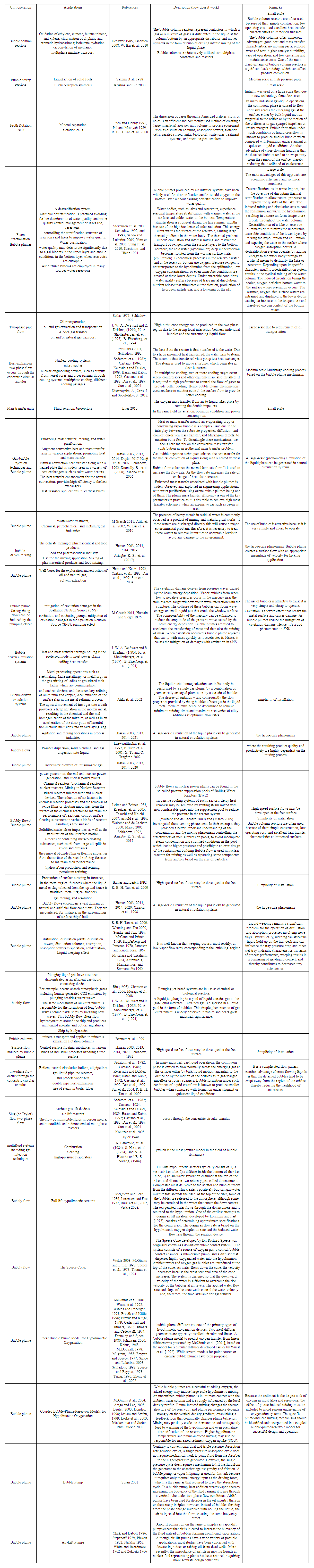
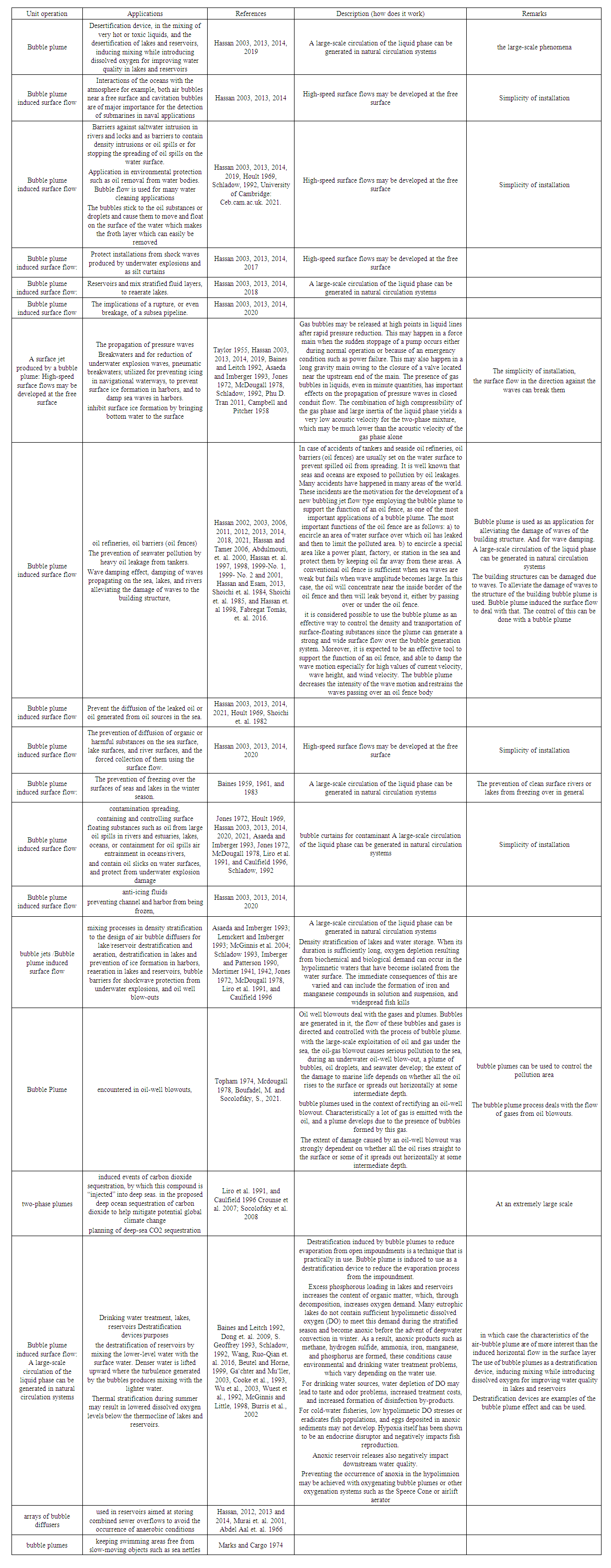
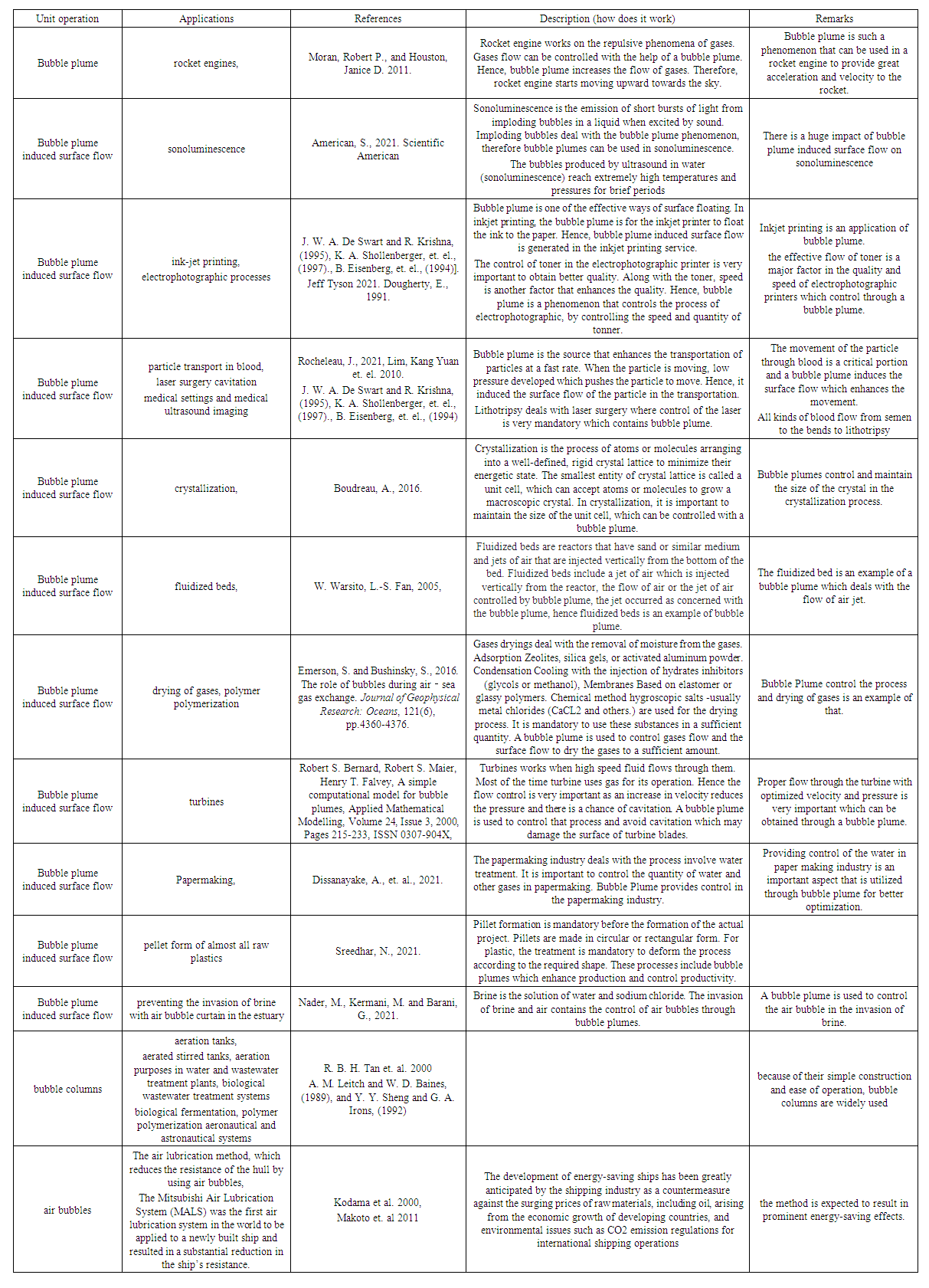
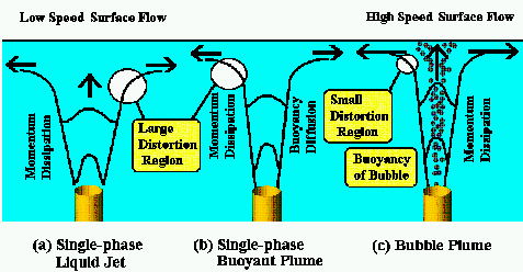

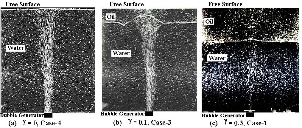
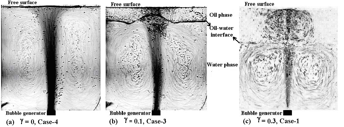
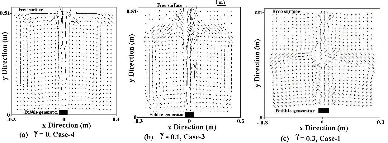
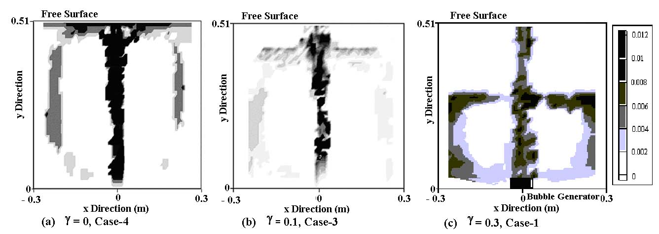
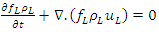

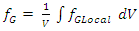
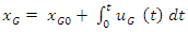
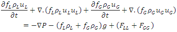
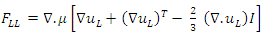
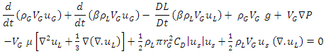
 number, Drag coefficient, and Morton number) were evaluated by Hassan 2022. The efficiency of the surface flow can be evaluated by improving its characteristics such as (velocity, height, width, and length) hence, (rapidly generating a powerful, high and broad surface flow overhead the bubble generator arrangement). The relations connecting these various parameters of bubbles that control their motion are found. The outcomes of the experimental study of bubble columns in which the variation in bubble parameters (diameter, velocity) as a function of the height of bubble plume, temperature, and gas flow rate are studied. Besides, the variation in the width of the bubble column is found to be dependent on the gas flow rate. Our results clearly show that a bubble plume is essential and is a powerful tool for several utilizations. The bubble plume is monitored by flow visualization, following which the images are analyzed, and bubble motion is deduced and studied. The parameters of the bubble (velocity, mean diameter), water temperature, gas flow rate, and plume height are calculated, and their inter-relationship is demonstrated. The results confirm that the flow is greatly affected by the bubble size, gas flow rate, and water temperature. The most important conclusions are paraphrased as follows:(a) Bubble size increases as water temperature increases. The bubble diameter increases by about one mm for every 10°C increment in water temperature. Moreover, the bubble size increases with increasing water height in the tank.(b) Bubble velocity increases as water temperature increases. The results confirm that the bubble velocity increases by a factor of about 1.5 to 2 for every 10°C increment in water temperature. In addition, the bubble velocity increases along the bubble plume as the height of water in the tank increases. Moreover, the magnitude of the bubble velocity at medium height in the tank is almost 50% greater than the magnitude of the bubble velocity just above the bubble generator. Furthermore, the magnitude of the bubble velocity just under the free surface is almost twice that just above the bubble generator.(c) The void fraction decreases as the water height increases and as the water temperature increases. The void fraction decreases up to twofold for every 10°C increment in water temperature.(d) The length of the bubble plume on the surface (i.e., the area that contains bubbles on the free surface, or “the length of the surface flow” in the horizontal direction) increases with increasing water temperature. Thus, a higher water temperature leads to stronger surface flow. Moreover, this area increases approximately in proportion to the gas flow rate.(f) Inside the bubble plume near the free surface, the bubble velocity and thus the velocity of the two-phase flow is greater, whereas the opposite is true in other regions. Thus, the generation of this high-speed flow is a primary contributor to the inducement of a strong surface flow.(g) The higher range of uncertainties occurs in the upper region, where the flow starts to change its orientation from a horizontal into a vertical direction, forming the surface flow, and especially with the higher gas volume flow rates Q3 = 50 × 10-5 (m3/s), where the flow starts to be turbulent.(h) The following properties are desired to efficiently generate surface flow: higher temperature, larger bubble size, deeper water, longer bubble plume, increased gas flow rate, and higher velocity. To sustain the surface flow process and increase its efficiency to generate surface flow, the parameters should achieve are greater bubble size, higher velocity, higher temperature, and greater gas flow rate.(i) The surface flow width increases with increasing both water temperature and gas flow rate. The width of the surface flow increases by about 2 to 4 mm for each 10°C enhancement of the water temperature, while the surface flow thickness increases about 0.2 to 1 mm for each 10°C enhancement, and the surface flow velocity increases about 0.1 to 0.2 m/s for each 10°C enhancement. Thus, a higher water temperature leads to stronger surface flow.(j) The bubble Reynolds number increases when both the gas flow rate and the temperature increase. (k) Drag coefficient decreases when both the gas flow rate and the temperature increase. (l) The
  number increases when the temperature increases while the Morton number decreases.(m) The velocity of the bubble and thus the two-phase flow velocity in the bubble plume and near the free surface is greater, whereas the opposite is true in other sectors. Thus, the production of this kind of flow with high speed is recognized as a primary contributor to the inducement of a powerful surface flow.The detailed investigation of an unstable meandering bubble plume created in a 2 m diameter vessel with a water depth of 1.5 m is reported for void fractions up to 4% and bubble size of the order of 2.5 mm. Simultaneous particle image velocity (PIV) measurements of bubble and liquid velocities and video recordings of the projection of the plume on two vertical perpendicular planes were produced to characterize the state of the plume by the location of its centerline and its equivalent diameter. The data were conditionally ensemble-averaged using only PIV sets corresponding to plume states in a range as narrow as possible, separating the small-scale fluctuations of the flow from the large-scale motions, namely plume meandering and instantaneous cross-sectional area fluctuations. Meandering produces an apparent spreading of the average plume velocity and void fraction profiles that were shown to remain self-similar in the instantaneous plume cross-section. Differences between the true local time-averaged relative velocities and the difference of the averaged phase velocities were measured; the complex variation of the relative velocity was explained by the effects of passing vortices and by the fact that the bubbles do not reach an equilibrium velocity as they migrate radially, producing momentum exchanges between high- and low-velocity regions. Local entrainment effects decrease with larger plume diameters, contradicting the classical dependence of entrainment on the time-averaged plume diameter. Small plume diameters tend to trigger ‘entrainment eddies’ that promote the inward-flow motion. The global turbulent kinetic energy was found to be dominated by vertical stresses. Conditional averages according to the plume diameter showed that the large-scale motions did not affect the instantaneous turbulent kinetic energy distribution in the plume, suggesting that large scales and small scales are not correlated. With conditional averaging, meandering was a minor effect on the global kinetic energy and the Reynolds stresses. In contrast, plume diameter fluctuations produce a substantial effect on these quantities (Marco et. al. 2009).Older studies of bubble plumes (e.g., by Kobus 1968 and Milgram 1983) produced a basic understanding of their global behavior. More recent detailed bubbly flow experiments (Hassan et al. 1992, Delnoj et al. 1999, Kubasch 2001, Rensen and Roig 2001, Hassan 2003, Marco et al. 2006) were conducted with confined flows or bubble columns. Various effects including recirculation in the vessel and the presence of walls can make the plume centerline and boundaries oscillate in three dimensions. These effects can also produce large structures driving the dispersed phase. The three-dimensionality of air-water bubbly flows was revealed in various experiments; (Milgram 1983, Castello-Branco and Schwerdtfeger 1994, Kuwagi and Ozoe 1999, Johansen and Boysan 1988 and Johansen et al. 1988) discuss plume precession and swirling. The radial distributions of the void fraction and the velocities were investigated by several authors, e.g. (Tacke et al. 1985, Johansen and Boysan 1988 and Johansen et al. 1988).Gas-liquid bubble columns are used extensively in the process industries for applications that require a large liquid bulk, i.e., applications involving a chemical reaction that is slow concerning the gas-liquid mass transfer or a chemical reaction that produces excessive amounts of heat. The gas-liquid two-phase flow prevailing in a bubble column is extremely complex, is dominated by a rich variety of coherent structures, and exhibits inherent unsteadiness. In recent years, a considerable effort has been made by various researchers to develop computational fluid dynamics (CFD) models for these gas-liquid two-phase flows (Lapin and LuK bbert 1994, Devanathan et. al. 1995, Delnoij et. al. 1997 a, b, c, 1998 a, Jakobsen et. al. 1997, Van den Akker 1998) Experimental validation of these CFD models is a prerequisite for the widespread acceptance of CFD models as a reliable (design) tool in the engineering community and indeed for the development of more sophisticated models. Contemporary CFD models predict the spatial and temporal distribution of key hydrodynamic variables associated with the two-phase flow in a bubble column. Accurate assessment of the validity of CFD results, therefore, requires an experimental technique that provides time-dependent and two- or three-dimensional information regarding these key hydrodynamic variables (i.e., velocity of both phases and void fraction) (Delnoij et. al. 1999). An ensemble correlation, double-exposure single-frame, particle image velocimetry (PIV) technique that can be applied to study dispersed gas-liquid two-phase flows discussed by (Delnoij et. al. 1999). The essentials of this technique were reviewed and several important issues concerning the implementation of the PIV technique were discussed. The capabilities of the newly developed PIV technique were demonstrated by examining the gas and liquid flow fields induced by a bubble plume rising in a rectangular bubble column (Delnoij et. al. 1999).Gas-liquid two-phase flow is observed frequently in diverse engineering systems covering chemical and petroleum processing, oil and gas extraction and transportation, thermal and nuclear power generation, etc. Despite its wide applications, two-phase flow is one of the least understood domains of fluid dynamics. The two phases can get distributed in many varieties (commonly termed as flow regimes or flow patterns) through any conduit during their motion. This renders the analysis and prediction of flow behavior extremely difficult. For decades scientists and engineers are making tireless efforts to understand two-phase flow through experimental investigations (Serizawa et al., 1975, 2002, 2003; Zun, 1990; Liu and Bankoff, 1993; Liu and Wang, 2001; Lucas et al., 2005 and 2006) and to model them by developing appropriate theory (Ishii, 1975; Ishii and Mishima 1984; Drahos et al., 1991; Yeoh and Tu, 2006; Lucas et al., 2007). Most of such endeavors consider two-phase flow through circular tubes. The motivation for such a choice emerges from the wide use of circular geometry in engineering applications. Nevertheless, flow through the annular passage of circular cross-section also occurs frequently. Well-bores for the exploration and extraction of oil and natural gas, double pipe heat exchangers, different cooling passages, various gas lift devices are examples where two-phase flow occurs through the concentric circular annulus. Accordingly, the flow of a two-phase mixture through annular passage has been investigated by several researchers (Sadatomi et al., 1982; Caetano, 1984; Kelessidis and Dukler, 1989; Hasan and Kabir, 1992; Caetano et al., 1992; Das et al., 1999; Sun et al., 2004). Sadatomi et al. (1982) studied air-water two-phase flow through the vertical annulus of 15 mm inner diameter and 30 mm outer diameter and determined the average void fraction using a quick closing valve technique. They also proposed the transition boundary for bubbly to slug flow. Caetano (1984) investigated air water and air kerosene two-phase flow through annuli and observed the transition of bubbly flow to slug flow at a void fraction of 18% and 25% for these two cases respectively. Kelessidis and Dukler (1989) conducted experiments for air-water flow in vertical concentric and eccentric annuli of 50.8 mm inner diameter and 76.2 mm outer diameter. They have used probability density function analysis of their conductivity probe signals to identify various flow regimes. Based on this a map has also been introduced for transitions of different flow patterns. Mathematical models based on the physical understanding of different flow patterns have also been developed that match well with their experimental results.Hasan and Kabir (1992) studied the effect of the annular gap on two-phase hydrodynamics using three different annuli. They have used the drift flux model to predict the average void fraction. Caetano et al. (1992) proposed a transition criterion for bubbly to slug flow using a hydrodynamic model based on eight empirical constants. Their flow pattern map matches well with the data of Hasan and Kabir (1992).Das et al. (1999) made an experimental observation for air-water upflow through concentric annuli of three different annuli (A: 50.8 mm/25.4 mm, B: 38.1 mm/12.7 mm, C: 25.4 mm/12.7 mm). To identify the distribution of void fraction in different flow regimes parallel plate type conductivity probe was used. Flow regimes were identified using a PDF of the signals obtained. Further, they have developed a transition model and compared the model prediction for bubbly to slug flow with different experimental results.Recently, Sun et al. (2004) observed bubble distribution patterns in their 4.1 m long borosilicate glass tubing of the annular cross-section. The outer diameter of the tube is 38.1 mm, and the inner diameter is 19.1 mm. Impedance void meter is used to measure the average void fraction of the test rig. Using the signals obtained from an impedance probe flow patterns have been recognized through a neural network. Their analytical model predicts the transition from bubbly to slug flow at a void fraction of 0.191. Some efforts have also been made for two-phase flow through annular conduit in horizontal and inclined orientations. The investigations made by Osamasali and Chang (1988), Ekberg et al. (1999), and Wongwises and Pipathattakul (2006) are worth mentioning.The review of the literature reveals that most of the previous works on two-phase flow through annulus are experimental in nature. From time to time some efforts have been made to analyze the flow phenomena through theoretical models. These are primarily phenomenological models developed for specific control volumes based on simplified assumptions. Moreover, in most cases, these phenomenological models were derived as extensions of the transition criteria previously proposed for circular geometry. Though these models are reasonably successful in predicting the regime boundary they do not provide much insight into the flow behavior at any location or its development along the conduit axis. It is needless to say that a continuum-based model that takes care of the spatial and temporal variation of the phase velocities along with the mutual interactions of the phases will not only be able to give a clear picture of the hydrodynamics but will also provide a better prediction of transition.The direct application of continuum-based models of fluid dynamics which are commonly used in the case of single-phase flow poses some difficulty in the case of two-phase flow. Further, the presence of different regimes in the case of two-phase flow increases the complexities. To tackle these situations, flow regime-based models are best suited as the underlying physics behind the regimes are different. Among different types of flow regimes, bubbly flow can be described as a homogeneous mixture of gaseous bubbles and a primary liquid phase. This leads various researchers to model bubbly flow using a homogeneous flow model or drifts flux model (Zuber and Findlay, 1969). Later, efforts have been made with the two-fluid model (Wu et al., 1998; Fu and Ishii, 2003) and the population balance model (Yeoh and Tu, 2004; Cheung et al., 2006) to investigate bubbly flow in the circular conduit. Though different numerical techniques (Bunner and Tryggvason, 2002) are employed to simulate bubble evolution in a circular tube, population balance technique coupled with two-fluid model emerges as an effective and robust technique (Cheung et al., 2006; Das et al., 2009 a, b; Yeoh and Tu, 2004) for predicting interfacial behavior in bubbly flow. Unfortunately, not much effort has been made to simulate bubbly flow and its transition in an annulus through the computational approach.Knowledge of bubbly flows is significant to various engineering systems such as nuclear waste treatment, biochemical reactors, and steel-making plants. Especially in the chemical engineering and industrial field, the mixing problems such as powder dispersion, solid blending, and gas dispersion into liquid have been an important issue because the resulting product quality and productivity are highly dependent on the mixing process (Luewisutthichat et. al. 1997, P. Tirto et. al. 2001 and X. Tu and C. Trägårdh 2002). In turbulent bubbly flow studies, there are two main interests: turbulence modification by bubbles and turbulent mixing due to bubble-driven liquid flows. Field surveys were carried out to investigate the surface jet flows and the resulting circulation patterns generated by diffused aeration in a shallow lake. The experimental conditions included point-source bubble plumes with very high air flow rates (100–400 L/min) relative to the shallow water depth (1.5 m). The results indicate that the surface jet velocity can be described by linear profiles. A simple returning flow model was proposed to describe the circulation flow patterns induced by the bubble plumes. The results were also applied to assess the impact of circulation on vertical algae migration, which is important for water quality management [ Tone et.al. 2017]. The flow in and around air-bubble plumes was studied. Two main ways of modeling, using either the entrainment assumption or the energy balance principle, are presented and briefly compared. Focusing attention on the entrainment coefficient α(z) which is found to be useful information for a plane plume, from the characteristics of the external flow (the “return flow”). A theory is presented for the external flow far outside a plane plume, at horizontal distances x≥3D, D being the water depth. A similar theory is presented for the surface flow close to the plume (both axisymmetric and plane cases covered). The theory replaces the physically non-permissible assumption about conservation of momentum around the turning region, used in earlier approaches, with an energy condition in which turbulent dissipation is included. Comparisons of the theories with experiments reported in the literature show reasonable agreement. [I Brevik, Ø Kristiansen 2002].To enhance mixing efficiency for a bubble-driven mixer such as a high-temperature mixing condition, air bubbling can be used. In such a system, gas is injected into a liquid bath from an orifice located at the bottom wall of a liquid container. (Durst et al. 1984) performed experimental studies on bubble-driven laminar flows by investigating liquid circulation and bubble streets with the Laser-Doppler system. It was reported that the liquid-phase circulation pattern is not sensitive to the actual shape of the void fraction profiles. (Johansen and Boysan 1988 and Johansen et al. 1988) studied fluid dynamics in bubble-stirred ladles by employing a Laser-Doppler system to measure the axial and radial mean and fluctuating velocities of the liquid phase. Air was supplied through a porous plug placed in the bottom wall of a cylindrical perspex-water model of a ladle. The recirculation flow motion and turbulence characteristics of liquid flow driven by air bubble stream in a rectangular water tank are studied by (Hyun et. al. 2010). The time-resolved Particle Image Velocimetry (PIV) technique is adopted for quantitative visualization and analysis. 532nm Diode CW laser is used for illumination and orange fluorescent (λex = 540nm, λem = 584nm) particle images are acquired by a 1280×1024 high-speed camera. To obtain clean particle images, a 545 nm long-pass optical filter and an image intensifier are employed, and the flow rate of compressed air is 3ℓ/min at 0.5MPa. The recirculation and mixing flow field is further investigated by the time-resolved Proper Orthogonal Decomposition (POD) analysis technique. It is observed that the large-scale recirculation resulting from the interaction between the rising bubble stream and the sidewall is the most dominant flow structure and there are small-scale vortical structures moving along with the large-scale recirculation flow. It is also verified that the sum of 20 modes of velocity field has about 67.4% of total turbulent energy (Hyun et. al. 2010).The flow structure surrounding bubbles is one of the interesting topics in the field of two-phase bubbly flow. A great number of experimental studies have been carried out to understand the fundamental mechanism of two-phase flows. The quick closing valve is one of the simplest and early developed methods to measure the average void fraction of steady and uniform two-phase flow (Liu 1993). To measure local void fraction, probe techniques and radiation techniques have been used for a long time (Serizawa et. al 1975, 1992 and Herringe and Davis 1976). In recent years, a laser Doppler anemometer has been applied to the bubbly flow measurement as a strong device to investigate the flow structure in detail, such as local void fraction profile, liquid velocity, and its fluctuation (Martin et. al. 1984 and Monji and Matsui 1995).Flow visualization techniques have also been used commonly in order to understand bubble deformation and coalescence phenomena (Tokuhiro et. al. 1998 and Takeda 1990).A measurement technique that can easily measure the velocity profile around a gas-liquid interface is required, even though it is necessary to clarify the flow structure around the bubble surface to understand the microscopic mechanism of bubbly flows. (Masanori et. al. 2000).A measurement system incorporating a UVP monitor has been developed and proposed for use in measuring multi-dimensional bubbly flow characteristics. The system has been applied to bubbly counter-current and co-current flows with a void fraction of less than 7% in a vertical rectangular channel to assess its capability.(1) The proposed system can measure instantaneous mixture velocity profiles in the channel.(2) By treating statistically, the measured instantaneous mixture velocity profiles, the velocity profiles of both phases, the void fraction profile and turbulence intensity of the liquid phase in the channel can be obtained.(3) The phase discrimination method of the measured instantaneous mixture velocity profile was proposed using the probability density function of the mixed velocities.The position of the bubble surface was decided, and the data were rearranged according to the distance from the bubble surface. From the results, it can be seen that the liquid velocity field surrounding bubbles can be classified into the following three regions: viscous sublayer, buffer region, and turbulence region.(4) In the laminar sublayer, the liquid velocity profile has a large gradient, and is greatly affected by the bubble motion but hardly affected by the liquid main flow.(5) The buffer region plays a role as a transition zone between the laminar sublayer and the main flow region. The motion of both phases influences the flow structure in this region.(6) The main flow region is far away from bubbles, so that bubble motion does not affect the continuous liquid phase. (Masanori et. al. 2000).The movement of bubbles is a basic subject in gas-liquid two-phase flow research because bubbles in water play an important role in solving problems in a wide range of experiments and projects [B. H. Davis, (2002) J. Magnaudet and I. Eames, (2000)]. The state and motion of bubbles are closed within the operating conditions, the nature of the liquid, and the form of ventilation. Implementing a bubble state by using visual methods has helped the development of the chemical industry and related fields [Y. Murai, et. al. (2000), H. Abdulmouti (2013), B. Jager and R. Espinoza, (1962)]. The motion of bubbles is very complex. The upward path and change in the direction of a bubble are known to be strongly related to bubble shape [E. T. White and R. H. Beardmore (1962)]. The motion of spherical bubbles is usually rectilinear. Once the bubble deforms into an oblate ellipsoid, instability sets in and results in a spiral or zigzag trajectory. Both bubble shape and bubble velocity of oblate ellipsoidal bubbles exhibit chaotic features [W. Luewisutthichat, et. al. (1997)]. In turn, the fluctuation of bubble shape is likely to cause oscillations in the drag force, leading to the chaotic fluctuation of bubble velocity in the streamwise direction. Therefore, despite periodic macroscopic motion, bubbles exhibit highly chaotic fluctuations in both the lateral and axial components along the zigzag path of a bubble ascent. At the same time, bubble orientation changes in such a way that the trajectory of the bubble plume tends to be perpendicular to the direction of instantaneous motion [W. L. Haberman and R. K. Morton, (1953)). From gas-disengagement experiments, it was inferred that both large and small bubbles exist in churn-turbulent flow [R. Krishna, et. al. (1991)]. Large bubbles rise fast through the column, whereas small bubbles display a longer resident-time distribution. Beyond a certain transition gas velocity, the small bubble holdup remains constant, whereas the large bubble holdup continues to increase with gas velocity [X. Junli, (2004)]. Bubbles in motion are generally classified as spherical, oblate ellipsoidal, or ellipsoidal cap, etc. In gas-liquid upward flow, bubbles move faster than the surrounding liquid (due to buoyancy), and large bubbles have greater upward acceleration than small bubbles. The actual bubble shape depends on the relative magnitudes of the forces acting on the bubble, such as surface tension and inertial forces [D. Bhaga and M. E. Weber, (1981)].The axisymmetric numerical calculations were used to investigate single Taylor bubbles' distinctive features and liquid flow around the bubbles. The tracking of the interface between two phases is accomplished by the solution of a continuity equation of the volume fraction of the gas phase. Natalia and Alexander 2007 consider a single air Taylor bubble rising through quiescent water in a long vertical tube, which allows it to reach a constant drift velocity. This allows us, in particular, to compare the calculated drift velocities with the analytical predictions of Davies and Taylor (1949). The authors study the flow in the whole pipe, thus including the upstream region, film flow, and the wake area in a single numerical model. The calculations are performed considering the axisymmetric Navier-Stokes equation assuming the whole flow laminar and then are repeated applying k-ε standard, k-ε RNG, k-ω standard, and the Reynolds stress turbulent models. The calculated results are compared with the experimental PIV measurements of van Hout et al. (2002), measurements of the wall stresses by (Mao and Duckler 1990 and 1991), and analytical results of Davies and Taylor (1949). The comparisons show that only using the Navier-Stokes equation the results agree quantitatively with the experimental measurements and with the analytical predictions (Natalia and Alexander 2007).Slug (or Taylor) flow is a flow regime important for many applications, for example, air-lift reactors, the flow of immiscible fluids in porous media, and monolithic and microchemical multiphase reactors. Among other advantages, the flow pattern between the bubbles increases mixing promotes a more uniform residence-time than single-phase flow, and the thin liquid film between the bubbles and the tube wall leads to extremely high heat and mass transfer coefficients (Kreutzer et al. 2005). Knowledge about the precise shape of the bubbles and the resulting variation in the thickness of the liquid film that separates the bubbles from the channel wall is of crucial importance for the prediction of heat and mass transfer rates. This knowledge, however, is difficult to predict theoretically, especially for non-circular channels and high Reynolds numbers. Experimental research is also difficult, especially in the monolith and micro-chemical reactors, where the dimensions of the system are small, leading to extremely small film thicknesses. Therefore, Computational Fluid Dynamics is believed to be a powerful tool in studying the two-phase hydrodynamics of slug flow in such channels (F. S. Sousa et. al. 2007). A hybrid front-tracking / front-capturing (F. S. de Sousa et al. (2004) method was used to simulate the flow of liquid slugs inside square cross-section channels. Second-order finite-difference discretizations are employed over a threedimensional cartesian staggered grid. The interface representation employed by their method allows an accurate prediction of the position of the interface, and therefore, accurate computations of the surface tension, which usually dominates this type of flow, are then obtained (F. S. Sousa et. al. 2007). Results of a single bubble rising through a quiescent fluid in a vertical square channel were present, at moderate Reynolds numbers. A comparison between circular and square cross-section channels is made by reporting bubble velocities and shapes for these two geometries. The velocities in the cross-sections of the channels are also reported, showing the presence of a secondary flow for the square channel. Differently from the axisymmetric geometries, the flow of Taylor bubbles in square channels leads to an increased wall shear at the corners of the channel was also shows that what is important to take into account in the determination of heat and mass transfer coefficients (F. S. Sousa et. al. 2007).Air-water bubbly jets are studied experimentally in a relatively large water tank with a gas volume fraction, Co, of up to 80% and nozzle Reynolds Number, Re, ranging from 3500 to 17,700. Measurements of bubble properties and mean axial water velocity are obtained and two groups of experiments are identified, one with relatively uniform bubble sizes and another with large and irregular bubbles. For the first group, dimensionless relationships are obtained to describe bubble properties and mean liquid flow structure as functions of Co and Re. Measurements of bubble slip velocity and estimates of the Drag Coefficient are also provided and compared to those for isolated bubbles from the literature. The study confirms the importance of bubble interactions to the dynamics of bubbly flows. Bubble breakup processes are also investigated for bubbly jets. It was found that a nozzle Reynolds Number larger than 8000 is needed to cause a breakup of larger bubbles into smaller bubbles and to produce a more uniform bubble size distribution. Moreover, the Weber Number based on the mean water velocity appears to be better criteria than the Weber Number based on the bubble slip velocity to describe the onset of bubble breakup away from the nozzle, which occurs at a Weber Number larger than 25 [Laime et. al. 2008].Recently, the studies on two-phase flow in the capillary tubes have much attention because of its useful applications such as micro cooler, heat exchanger, and microreactor. Particularly, the slug bubble flow mode provides good performance for heat and mass transfer. For the design of those devices, the control of the two-phase flow pattern must be required. It is known that the coalescence and breakage of bubbles are often negligible in the capillary tube. Therefore, it is very important to predict the slug bubble size formed at the two-phase flow supply system. (Kreutzer, et. al. 2005, Takashi and Koichi 2007). A slug bubble formation model in a capillary tube is proposed. On the other hand, the effects of gas flow rate, nozzle diameter, liquid velocity, and capillary diameter on the shape and volume of bubbles formed in the capillary tube were experimentally investigated. To ensure the proposed model, the calculated results were compared with the experimental results. The bubble volume rapidly increased during the early period of bubble growth and then it increased proportionally to the time (Kreutzer, et. al. 2005, Takashi and Koichi 2007).When gas and liquid flow simultaneously in a pipe, a variety of configurations (dispersed, annular, and transition flow) related to the spatial distribution of the two phases can be observed. These configurations termed flow patterns can be recognized by the flow maps Mandhane (1974). The one most configuration frequently occurs over certain ranges of flow rates is slug flow. This flow is encountered in large industrial processes as such oil and gas wells, gas-liquid pipeline reactors, and process vaporizers. It is a complicated flow pattern as reported by Fernandes et al., 1983, Orell, and Rembrand (1986). It is characterized by a quasi-periodic alteration of long bubbles and liquid slugs. In vertical flow and at low liquid viscosity, the Dumitrescu-Taylor bubble Clanet et al. (2004) has a generally spherical nose and a flat bottom. It fills most of the pipe cross-section and around it, the liquid moves in the form of a film. The Dumitrescu-Taylor bubble has been the subject of numerous studies Dumitrescu (1943), Davies and Taylor (1950), Collins (1978), Mao, and Dukler (1990), Polonsky et al. (1999), Nogueira et al. (2006), etc. Generally, most of these studies were done in stagnant and co-current vertical flows; few of them were conducted in counter current vertical flows in small tubes Griffith et al. (1961), Nicklin (1962), and Martin (1976). The comprehension of the behavior of the bubble inflow is important to understand the general phenomenon of gas-liquid flow. So, the flow around the individual bubble remains always a very attractive subject of research and any additional contribution of experimental data is useful for the progression of the physical model development (S. Benattalah et. al. 2011).When a liquid flow through a tube, the motion of the long bubbles results from the complex influence of both buoyancy and the mean motion of the liquid. In upwards flow, the motion of the bubble has been studied by several authors Griffith et al. (1961), Nicklin et al. (1962), Collins (1978), Bendiksen (1985) while in downward flow few studies are carried out Martin et al. (1976), Griffith et al. (1961) and Nicklin et al. (1962). The study of the hydrodynamics of liquid film surrounding the Dumitrescu-Taylor bubble has required various works both experimental and numerical, Goldsmith et al. (1962), Brown (1965), Mao and Dukler (1990), Polonsky (1999), Van Hout (2002), Nogueira et al. (2006) and Bugg et al. (1998) and Bugg and Saad 2002. For the flow which occurs behind the bottom of the Dumitrescu-Taylor bubble, one can quote works of Campos and Guedes (1988) and those of Pinto and Campos (1996), and very few studies have been concerned with the field of flow inside the Taylor bubble. The first visualization of the flow velocity fields inside the gas Dumitrescu-Taylor bubble was carried out by Filla et. al. (1976), by forming a white smoke inside the Dumitrescu-Taylor bubble using a simple chemical reaction. The method consists to form an Ammonia NH3 bubble which will cross a column of liquid made up of two immiscible layers. The first layer is carbon tetrachloride enough deep to give the bubble the possibility to reach the limit velocity. The second is a chloride acid solution HCL. The emergence of the NH3 bubble into the acid leads to form an Ammonium Chloride fog near the interface which was swept down to the bottom of the bubble. Soon, after the chemical reaction, a downward motion near the interface was clearly shown, indicating a toroïdal vortex. When the diameter is small, this method allows only to see furtive vortex but cannot obtain quantitative velocity profiles as for the first measurements of gas velocities within a Dumitrescu- Taylor bubble which were realized by Eccles (1972), by using a miniature hot wire anemometer. The Dumitrescu-Taylor bubble is held stationary by a counter-current flow in a 27 mm diameter tube. The measurements were carried out in the upper hemispherical portion of the bubble (L/D<2.6) with a hot wire which doesn’t enable the detection of the flow direction. It is seen that these results are in excellent agreement with the theoretical predictions. It is noted also that the theoretical predictions and experimental measurements have divergences at the level velocities in the center, and those inside the interface of gas/liquid (S. Benattalah et. al. 2011).An experimental investigation on the Dumitrescu-Taylor bubble in counter-current laminar downward flow in the vertical pipe of a small internal diameter pipe is presented by (S. Benattalah et. al. 2011). The experimental design is realized to work for low and stable liquid flow rates. The Dumitrescu-Taylor bubble may be stationary or can be in motion with an ascending or descending velocity, and this displacement depends on the downward liquid flow rates. Consequently, the advantage of this device is to carry out the measurements of the velocities inside the gas Dumitrescu-Taylor bubble by Laser Doppler Velocimetry (LDV). Starting from the visual observations and image acquisitions with a fast camera, a qualitative description was brought on the hydrodynamic behavior of the liquid film and the ripples created at the bottom of the Dumitrescu-Taylor bubble. The experimental results show a presence of a long toroïdal vortex inside the gas bubble. It should be noted that before (S. Benattalah et. al. 2011)’s work using a hot wire does not show the existence of this vortex. Additionally, other hydrodynamic magnitudes were measured as the liquid film thickness, the Dumitrescu-Taylor bubble rising velocity as well as the erosion bubble. Detailed descriptions are brought concerned with this erosion. Strange phenomena have been observed primarily ahead of the nose of the bubble and on the side of its end (S. Benattalah et. al. 2011).An upward air-water bubbly flow in a pipe was studied experimentally, with special attention being paid to the transition from bubbly flow to slug flow. The pipe diameter was 72 mm and the height 18 m. The Reynolds number based on liquid flow was low-to-moderate (Usl < 0:2 ms-1), so that bubble break-up due to turbulence was nearly absent. Three different inlet devices were used, which had a significant influence on the initial bubble size and initial bubble concentration distribution. The transition from bubbly flow to slug flow was shown to be strongly dependent on the inlet configuration, particularly on the bubble size. Several theoretical models for the transition from bubbly flow to slug flow were reviewed. The (Y. Taitel et al. 1980) approach was combined with a bubble-size-dependent critical void-fraction expression of (C. H. Song et al. 1995). This new formulation for the transition from bubbly flow to slug flow was in good agreement with the measurements (S. Guet et. al. 2002).It was shown experimentally that the efficiency of the gas-lift technique at low liquid flow conditions is very dependent on the inlet device used for injecting the gas. When small bubbles are generated during gas injection, the transition from bubbly flow to slug flow occurs at higher values of the void fraction than for large bubbles. Large values of the void fraction under bubbly flow conditions lead to large values of the liquid flow. This is not the case when large bubbles are generated during injection, as large bubbles would lead to slug-flow conditions already at low values of the void fraction. In addition, it is known that slug flow has a very detrimental effect on the efficiency of the gas-lift technique (S. Guet et. al. 2002).It was also shown that the transition from bubbly flow to slug flow as a function of the injected bubble size can reliably be predicted by (Y. Taitel et al. 1980) criterion, combined with the critical void-fraction relation of (C. H. Song et al. 1995). When for a practical application the size of the injected bubbles is known, the critical void fraction (for the transition from bubbly flow to slug flow) can be calculated with the critical void-fraction relation of (C. H. Song et al. 1995). (Y. Taitel et al. 1980) criterion can then be used to calculate the optimal influence of the injected gas flow rate on the liquid flow rate (S. Guet et. al. 2002).Gas-liquid flows are of great importance for many industrial processes. A well-known example is the gas lift technique that is for instance applied in the oil industry. In this technique, an increase, or a generation of an upward liquid flow in a vertical pipe is achieved by injecting gas at the bottom of the pipe. The range of conditions for the liquid flow rate (before gas injection) can be very wide, from conditions without a net liquid flow to conditions with a fully developed turbulent flow (S. Guet et. al. 2002).Bubbly flow and its transitions in vertical annuli are studied using the population balance technique. Bubble breakup and coalescence are accounted separately to track the evolution of the bubble size during the simultaneous flow of gas and liquid. The conventional two-fluid model is used to simulate hydrodynamics. The model enables the prediction of a void age profile at any axial location. The presence of a peak in the void distribution at the walls of the annulus, center of the annulus, and both at walls and centers are observed depending on the phase superficial velocities. Further, the transition from bubbly to slug and bubbly to dispersed bubbly is predicted based on the evolved bubble size. The model prediction gives a good match with the experimental data and existing theory. A shift in the transition boundary is noted due to the variation in the inlet bubble size and the dimension of the annulus (A.K. Das and P.K. Das 2010). The effect of bubble-bubble interaction in homogeneous bubbly flow is investigated by direct numerical simulation and a bubbly mixture model for bubbly shock flows at void fraction 0.4%– 13%. It is found that the bubble-bubble interaction effect is significant at a void fraction higher than O (1) % and decreases the amplitude and wavelength of the macroscale oscillations in the dispersive shock structure. For the modeling of the bubble-bubble interaction effect, the local volume averaged Rayleigh–Plesset (LVARP) equation, which is an extended version of the original Rayleigh–Plesset equation, is proposed. The results of the bubbly mixture model using LVARP agree well with the direct simulation results for bubbly shock flows at a void fraction up to 13%. The bubble-bubble interaction in nonuniform bubbly flows is also investigated in bubbly flows with randomized initial bubble positions. It is found that the LVARP model predicts the ensemble-averaged behavior with reasonable accuracy (Jung et. al. 2010).The continuum bubbly mixture model (L. Van 1968, 1972, A. Biesheuvel and L. Van 1984, L. D’Agostino et. al. 1988 and C. E. Brennen,1995) in which macroscopic conservation equations are coupled with the microscopic bubble dynamics equation has been considered as a sound approach to the study of bubbly flows (liquid flow containing small gas bubbles). Several authors (D’Agostino et. al. 1988, L. D’Agostino and C. E. Brennen 1989, Y. C. Wang and C. E. Brennen 1999, T. Colonius et. al. 2000 and A. T. Preston et. al. 2002) used this model to study dilute bubbly cavitating flows and showed that the model is capable of resolving flow features which cannot be captured with barotropic two-phase models. The bubbly mixture model has also been applied to practical cavitating flows by several researchers (A. Kubota et.al. 1992 and Y. Chen and S. D. Heister 1996). In these studies, the Rayleigh–Plesset equation (or its simplification/ modification) and additional assumptions are used to describe the bubble dynamics. For practical cavitating flows, however, additional effects on bubble dynamics such as thermal diffusion, bubble-bubble interaction, and relative motion between bubbles and liquid should be carefully considered to obtain quantitative results. Many authors stressed the importance of the thermal diffusion effect on the bubble dynamics, and among the many mathematical analyses of the thermal diffusion effect, the model of Prosperetti (A. Prosperetti 1991) is notable. With the development of computational methods, the study of thermal diffusion has progressed rapidly. Kameda and Matsumoto (M. Kameda and Y. Matsumoto 1996) took into account the thermal diffusion effect in their bubbly shock flow simulation by solving the full set of partial differential equations (i.e., compressible Navier– Stokes equations) for spherical bubbles. This is computationally demanding but they obtained good agreement with experiments. Recently (A. T. Preston 2007) proposed a reduced-order model of diffusive effect on the bubble dynamics and showed its validity by comparing the results with computations of the full partial differential equations. Their model is applicable to practical, complex bubbly flow computations.The bubble-bubble interaction is another important effect for nondilute bubbly flows. In practical cavitating flows, the local void fraction (gas volume fraction) often exceeds the dilute limit [O (1) % typically] and the bubble-bubble interaction effect is particularly significant in the high void fraction regions. The original Rayleigh–Plesset equation derived for single bubble dynamics is not valid in that regime.There have been several studies, (R. E. Caflisch et.al. 1985, J. Rubinstein 1985, and A. S. Sangani 1991) in which bubbly flows at nondilute, finite void fraction was investigated in terms of “effective” equations intended to capture wave phenomena. (R. E. Caflisch et. al.1985) derived an effective wave equation for nondilute bubbly mixture applying the multiple-scale method in the linearized regime. (Rubinstein 1985) applied the approach of Caflisch et al. to the nonlinear analysis of a periodic lattice multi bubble system and derived an “improved” Rayleigh– Plesset equation, which includes the effects of interactions between the bubbles. (A. E. Beylich and A. Gülhan 1990) tried to find the correction factor for the bubble-bubble interaction effect by fitting the result of the model equation to their experimental data for a bubbly shock flow. (G. L. Chahine and R. Duraiswami 1992) studied the response of a few bubble clusters to a prescribed outer pressure (i.e., P∞) with an asymptotic approach and a boundary element method. (A. (Kubota et.al. 1992) modeled the bubble bubble interaction in their hydrofoil computation by adding the velocity potential of other bubbles with the assumption of local homogeneity, which is the simplified approach of (G. L. Chahine and R. Duraiswami 1992 and G. L. Chahine 1983). Recently (C. F. Delale 2001) proposed a similar model and applied it to quasi-one-dimensional (quasi-1D), cavitating nozzle flow. (Y. Chen and S. D. Heister 1996) considered bubbly cavitating flow at high void fraction using a form of the Rayleigh–Plesset equation that was rewritten in terms of the density equation by volume averaging.The diversity of applications of bubble plumes has triggered a host of experimental contributions, aimed at determining time-averaged velocities in tanks ranging from 1 m in diameter up to sinkholes of 50 m in depth (Milgram, 1983). Needless to say, the interpretation and comparison of results coming from such a variety of scales are complex. In fact, the shape of containers, different tank sizes and geometries, and the complex nature of the problem make the interpretation of results somewhat cumbersome. This is complex even in non-stratified conditions. Tools to extrapolate bubble-plume behavior in small tanks to big tanks are largely needed.Experimental evidence regarding the behavior of bubble plumes in two tanks of different sizes, under non-stratified conditions, was presented by (L. E. Rincón et. al. 2004). The smaller vessel has been geometrically scaled down from the larger one with a relation 1:10. Velocity measurements were performed in both tanks with acoustic sensors (ADVs) and time-averaged velocity profiles obtained at both scales were compared. This comparison was used to support a methodology to scale vertical and horizontal (radial) distances in bubble plumes, while allowing for the simulation of portions of the reservoirs. The bubble-slip velocity and length scale D were determined as the relevant scales in the analysis. The previous scaling of bubble plumes, based on the preservation of the number MH (Asaeda and Imberger, 1993) and the use of the ratio diffuser depth/airflow rate, appear as a special case of this more general theory (L. E. Rincón et. al. 2004).One of the reasons why bubbly flows are difficult to simulate correctly is that the forces exerted on the bubbles are mainly coming from the surrounding fluid and not from the inertia of the bubble itself. Therefore, a thorough understanding of the interaction between the bubbles and the fluid is needed. To this end, a 2D experimental technique is necessary, which can give accurate information concerning both the speed and diameter of the bubbles as well as the speed of the surrounding fluid (S. Dehaeck et. al. 2005).The functional of bubble columns dependence on the velocity of an air bubble has been determined experimentally by numerous investigators. When rising through an infinite stagnant liquid, the single bubble’s terminal velocity is of fundamental importance in two-phase flow M. A. R. Talaia, (2004), as well as in other types of flow. The knowledge of bubble properties, including bubble velocity, bubble size, gas holdup, and specific interfacial area, is of prime importance for the proper design and operation of bubble columns A. Tomiyama, (2004) and A. Tomiyama, et. al. 2001.There exist many techniques today, which give only a part of the required information. Backlighting is one of these. It is a well-known technique that simply records the shadow images of diffusively illuminated bubbles. Although this technique can give the size and velocity of the bubble, it cannot give its precise location along the optical axis of the camera since the position and dimension of the detection volume are uncertain. This makes accurate gas-water interface studies almost impossible, and measurements of the void fraction are crippled because of it. Another, more recent technique in droplet diagnostics is Interferometric Laser Imaging for Droplet Sizing (ILIDS) (Koenig et al. (1986); Glover et al. (1995)), which is also known under different names as IPI (Interferometric Particle Imaging) in Damaschke et al. (2002a) or PPIA (Planar Particle Image Analysis) in Hess (1998). It is based on the interference pattern observed when reflection and refraction spots on the droplet surface (glare points) are seen out-of-focus. The main advantage of this technique is its ability to measure microscopic particles while maintaining a relatively large field of view. However, observing an interference pattern that can be 10 to 100 times larger than the actual bubble, leads to a severe restriction on the allowable amount of bubbles per mm3 since only a minimal overlap of the images is allowed. This concentration limit was investigated for different optical configurations in Damaschke et al. (2002b). The configurations examined by these authors also demonstrate a second drawback of the technique: its low dynamic range (dmax/dmin ≈10). The concentration limit can be improved if the glare points are observed out-of-focus in only one dimension through the use of a cylindrical lens, as proposed by Akasaka et al. (2002). Possibilities to increase the dynamic range were investigated by several authors. Damaschke et al. (2002a) suggested the use of a second laser sheet under a small inclination angle (15-40°) in their Global Phase Doppler technique (GPD). If the size ranges of the ILIDS- and the GPD-mode are made to overlap, an extension of the dynamic range can be accomplished (≈ 100). Another possibility to overcome both the concentration limit as the limited dynamic range is the use of holographic techniques as suggested by Burke et al. (2002). After identifying different particles in the reconstructed in-focus image, each particle is processed individually through the application of a mask. In this way, an isolated ILIDS pattern can be reconstructed for the smallest particles from the holographic recording, which is then processed to yield the droplet size. This masking procedure distinctly increases the allowable number density. Larger droplets are reconstructed in focus and their glare point pattern gives the diameter of the particle. The largest diameter that can be measured in this way is of the same order of magnitude as the field of view of the camera, leading to a considerable increase in dynamic range. Apart from size measurements, velocity measurements are probably equally important in investigating bubbly flows. Typically, such measurements with ILIDS would involve cross-correlating two pulsed out-of-focus images (Maeda et al. (2002). Another approach was presented by Dantec Dynamics (2003) and Damaschke et al. (2002a). They observed the glare points in-focus with a second camera to yield more accurate (PTV-like) velocity information, despite a more cumbersome set-up and associated calibration procedure. Although most of the development on ILIDS has been performed on droplets, Niwa et al. (2000) showed how it could be applied to bubbly flows if an observation angle of 45° is used (S. Dehaeck et. al. 2005).A novel measuring technique for bubbly flows, named Glare Point Velocimetry and Sizing (GPVS), was developed to measure both bubble size and velocity with high accuracy in a 2D plane. This is accomplished by observing glare points in focus under an observation angle of 96◦. When a second laser sheet is added, even higher accuracies are obtained, and the relative refractive index of the bubble can be measured. It also allows non-spherical bubbles to be rejected and arbitrary angles to be used (e.g., 90°). The accuracy of the size and refractive index measurements was found to be within 1,3% (S. Dehaeck et. al. 2005).Computation of two-phase flows and, in particular, bubbly flows is a very active research topic in computational fluid dynamics (CFD), see, for instance (F.S. de Sousa et. al. 2004, Esmaeeli and Tryggvason 1998, M. Sussman and E. Puckett 2000, G. Tryggvason et. al. 2001 and 2006, S.P. van et. al. 2005 and 2008, J. Hua and J. Lou 2007, E. Marchandise et. al. 2007, R. Singh and W. Shyy 2007 and M. Sussman et. al. 2007). Understanding the dynamics and interaction of bubbles and droplets in a large variety of industrial processes is crucial for an economically and ecologically optimized design. Two-phase flows are complicated to simulate because the geometry of the problem typically varies with time and the fluids involved can have very different material properties. A simple example is that of air bubbles in water, where the densities vary by a factor of about 800. Mathematically, bubbly flows are modeled using the Navier–Stokes equations coupled with an interface advection equation, which can be approximated numerically using operator-splitting techniques. In these schemes, equations for the velocity and pressure are solved sequentially at each time step, and the fluid density is explicitly advected. In many popular operator-splitting methods, the pressure correction is formulated implicitly, requiring the solution of a linear system at each time step. This system takes the form of a Poisson equation with discontinuous coefficients. Solving these systems typically consumes the bulk of the computing time, even though the operator is elliptic.The numerical simulation of two-phase fluid flow, where bubbles or droplets of one phase move against a background of the other phase was considered by (S.P. MacLachlan et. al. 2008). Such flows are governed by the Navier-Stokes equations, the solution of which may be approximated using a pressure-correction approach. Within such an approach, the computational cost is often dominated by the solution of a linear system corresponding to a discrete Poisson equation with discontinuous coefficients. The efficient solution of these linear systems using robust multilevel solvers was explored, such as deflated variants of the preconditioned conjugate gradient method, or robust multigrid techniques. These families of methods were considered in more detail and compared to their performance in the simulation of bubbly flows. Some of these methods turn out to be very effective and reduce the amount of work to solve the pressure-correction system substantially, resulting in efficient calculations for two-phase flows on highly resolved grids (S.P. MacLachlan et. al. 2008).The mean gas fraction distribution in the two-phase flow of a gas-liquid bubble plume set to develop adjacent either to a wall or to another bubble plume was described. When this happens, the plume exhibits a type of Coanda effect, bending either towards the wall or the other plume. The local mean gas fraction measurements are carried out using the electro-resistivity probe technique in an air-water system. The deflection angle of the plumes is shown to present dependence on the modified Weber and Froude numbers of the bubbles. A Gaussian distribution for the mean gas fraction profile, observed to exist for axisymmetric single plumes, is shown not to occur in flow geometries where the Coanda effect is allowed to set in. The transition zone between the downstream flow where two Gaussian plumes are observed and the far upstream flow where the plumes are seen to merge onto a single plume is characterized. Photographs of the flow are shown to illustrate the phenomenon. Results are present for two- and three-dimensional mean gas fraction distributions. Furthermore, a simple theory based on integral methods is advanced for the prediction of the plume deflection angle; the theory considers a variable entrainment coefficient (Atila et. al. 2002). Buoyant plumes in multi-phase flows are a common occurrence in the chemical and metallurgical industries. Indeed, bubble plumes provide an effective and relatively simple way of achieving large degrees of agitation in the flow of fluids which are otherwise hostile to intrusive elements. For example, in the steelmaking industry, gas stirred melt ladles are commonplace. The upward movement of inert gas into a bath provokes a large agitation in the molten metal, resulting in the chemical and thermal homogenization of the mixture, as well as in an acceleration of the absorption of harmful non-metallic inclusions into an overlaying slag. The liquid metal homogenization can indistinctly be performed by a single gas plume, by a combination of geometrically arranged plumes, or by a curtain of bubbles. The degree of agitation – and consequently the flow properties provided by rising bubbles of inert gas in the liquid metal medium must hence be determined to achieve minimum mixing times and maximum recoveries of alloy additions at optimum flow rates. To measure the main characteristics of the plumes, an electro-resistivity probe system was used. This system was chosen for being simple while still being capable of conveying much useful information on the phenomenon. Here, it suffices to say that by an analysis of the experimental data through the mean gas fraction profiles, the deflection of the plume has been evaluated as a function of several parameters of interest including the gas flow rate and the distance between the point sources (Atila et. al. 2002).The single bubble plume flow has been extensively studied both theoretically (Ditmars and Cederwall, 1974; Milgram, 1983; Brevik and Killie 1996) and experimentally (Milgram, 1983; Castillejos and Brimacombe, 1987; Barbosa and Bradbury, 1996) by many authors in the past three decades. For the integral approaches, the flow has been divided into three distinct regions where some dominant effects prevail (Milgram, 1983). The buoyancy-dominated region is normally referred to as the ‘‘zone of established flow’’. This was the region of main interest by (Atila et. al. 2002).Bubble columns are intensively utilized as multiphase contactors and reactors in chemical, petrochemical, biochemical and metallurgical industrials. For the operation of two-phase flows in bubble columns, insight into primary parameters such as bubble size, shape, and velocity as well as a void fraction is essential. The measurements of bubble properties in heterogeneous bubbly flows in a square bubble column were performed. A four-point optical fiber probe was used for this purpose. The accuracy and intrusive effect of the optical probe were investigated first. The results show that the optical probe underestimates bubble properties, such as bubble velocity, local void fraction. The presence of the probe in the bubble column influences the local flow conditions. Particularly, when the probe is placed close to the liquid surface, this influence is more pronounced. Furthermore, two methods determining the interfacial area were compared. The results from both methods agree quite well at low superficial gas velocity, whereas large discrepancies are found when superficial gas velocity increases. Finally, the effect of column height on bubble properties was studied. No significant difference was found for the three investigated columns (W. Bai et. al. 2010). Optical fiber probes (Cartellier 1990, Mudde and Saito 2001) have the advantage of low cost, simplicity of setup, and easy interpretation of the results. With an optical fiber probe, the measurement of local void fraction becomes possible. Furthermore, using a four-point optical probe, properties of bubbles can also be studied, such as bubble velocity and bubble size. The effect of column height on the bubble properties, such as bubble velocity, local void fraction, interfacial area, and equivalent diameter, was discussed. (W. Bai et. al. 2010).Bubble columns are widely used across a range of industries. The work described by (Bennett et. al. 1999), although applied to minerals separation flotation columns, is equally applicable in the wider context of bubble columns. In flotation columns, several flow regimes may be obtained and are difficult to visualize and detect. An Electrical Capacitance Tomography (ECT) sensor has been applied to investigate the potential of ECT for flotation column visualization and control. Different methods of flow regime analysis are reported including a repeatable and robust analytical procedure that has been designed to quantify heterogeneity. The use of ECT is examined for distinguishing homogeneous bubble flow and churn flow. Then a quantification of these flow regimes is compared to simple secondary parameters (derived from multiple frame measurements) obtained from images and capacitances. A wide variety of conditions were created to test the viability of the method using different spargers, frother concentrations, and height between sparger and sensor (Bennett et. al. 1999). ECT can be used to obtain information on flow regime, bubble size, gas concentration radial profile and flow heterogeneity in liquid/gas flows in bubble columns and flotation processes where conductivity is low (Bennett et. al. 1999). It was realized that aside from the actual flow regime many inter-related aspects of flow contributed to the sensor measurement including bubble size and size distribution, bubble swarming, and radial gas concentration (radial profile). Due to its high sensitivity and low noise, it was also believed that the sensor showed promise in highlighting furthermore detailed aspects of flow and these were investigated (Bennett et. al. 1999).Water quality in reservoirs is affected by several factors, including thermally induced stratification coupled with eutrophication. Specifically, “a density and temperature structure with a well-mixed top surface layer which is separated from a deep bottom layer by an intermediate layer of strong temperature gradients” is created by Lemckert and Imberger 1993. This intermediate layer inhibits vertical heat and mass transport between the upper and bottom layers. As a result, water quality may deteriorate significantly due to algal blooms in the upper layer and anoxic conditions in the bottom layer when reservoirs are eutrophic (Schladow 1993). Since the early 1950s, bubble plumes produced by air diffuser systems have been widely used for destratification and/or to add oxygen to the bottom layer without causing destratification to improve water quality. The main advantages of this approach are economic efficiency and technical soundness (Sahoo and Luketina 2005; Yum et al. 2005). Air diffuser systems are employed in many source water reservoirs in Korea, but field engineers are demanding more detailed design and operational guidelines so that they can better address various field conditions for consistent performance (Sung et. al. 2010).Bubble plumes in liquid media have been the subject of numerous studies, as they are widely used in industry for various purposes. Many studies have focused on the structure of bubble plumes and their interactions with the surrounding water environment (McDougall 1978; Baines and Leitch 1992; Leich and Baines 1989; Asaeda and Imberger 1989, 1993; Chen and Cardoso 2000; Sahoo and Luketina 2003; Socolofsky and Adams 2003, 2005; Bombardelli et al. 2007). Researchers have developed various plume models with different variables to address different questions and obtain related data (Sung et. al. 2010). Effects of bubble size, bubble diffusing area, and other parameters in air diffusers on destratification are studied using laboratory- and pilot-scale tanks with two layers. A dimensionless group involving such variables as bubble size, bubble diffusing area, and tank area are used to quantify these effects. Based on the results of experiments, a model is developed to predict destratification efficiency. Bubble diameter and overall tank area are found inversely related to destratification efficiency while bubble diffusing area is directly related to destratification efficiency (Sung et. al. 2010).For studies on the characteristics of bubble flow in a rectangular channel (20×100mm), a new electrode-mesh tomograph has been applied. The measuring principle is based on local conductivity measurement. The applied sensor scans the local void fraction distribution in 2 parallel planes, separated 1.5 mm in the flow direction, with a resolution of 3.0×2.2 mm and an overall sampling rate of 1200 Hz (all 256 points). Algorithms for the calculation of the local instantaneous void fraction distribution and the true gas velocity are presented. Based on these values the approximate shape of bubbles was reconstructed and the gas volume flow through the sensor was evaluated. The superficial gas velocity, as well as the local distribution of the gas volume flux, was calculated. An extensive sensitivity study illustrating applicability and accuracy is presented, based on experimental observations as well as theoretical considerations. The evaluated results are compared with high-speed video observations of the flow field as well as data comparing the reconstructed volume flow with measurements by a laminar flow meter. Good agreement can be stated in general. (Steffen and Masanori 2002).A limitation on the metal throughput of a gas fluxing unit is posed by splashing and spraying of metal droplets as the gas throughput is increased to keep pace. In an investigation at Berkeley funded by DOE (OIT DE-FC07-01ID14192) and Alcoa, droplets ejected because of bubble rupture at the free surface of molten metal are examined via high-speed digital photography and image tracking software. Experiments are carried out in a custom-built, glass-walled vessel designed for observation of splashing and spraying at the surface of a low melting temperature alloy. A controlled bubble release system permits variation in bubble size, the release of single or multiple bubbles, or a continuous stream of bubbles. The effects of melt depth in the vessel, oxide formation at the melt surface and the presence of a second liquid on droplet behavior are also examined. Droplet numbers, velocities, trajectories, and size distributions are determined for the aforementioned conditions with image analysis software (Autumn and James 2005).Bubble plumes of various void fractions and sizes were produced by varying the flow velocity of a water jet impinging normally on a water surface. The bubbles entrained at the surface were carried downwards by the fluid flow to depths ranging from 33 to 65 cm and formed roughly cylindrical plumes with diameters ranging from 12 to 27 cm. The acoustic emissions from the plumes were recorded onto digital audio tape using a hydrophone placed outside the cloud at distances ranging from 50 cm to 16.0 m. Closeup video images of the individual bubbles within the plume were also taken to gain knowledge of the bubble size distributions. The experiments were performed in both fresh-water and salt-water environments. The fresh-water clouds emitted sounds with a modal structure that was significantly different from that produced by the salt-water clouds. Furthermore, the smaller bubbles present in the salt-water clouds have a fundamental effect on the amplification of turbulence noise, generating sound at significant levels for frequencies up to several hundred Hertz (Gregory and Michael 2000).Detailed measurements of bubble composition, dissolved gas concentrations, and plume dynamics were conducted during a 9-month period at a very intense, shallow (22-m water depth) marine hydrocarbon seeps in the Santa Barbara Channel, California. Methane, carbon dioxide, and heavier hydrocarbons were lost from rising seep bubbles, while nitrogen and oxygen were gained. Within the rising seawater bubble plume, dissolved methane concentrations were more than 4 orders of magnitude greater than atmospheric equilibrium concentrations. Strong upwelling flows were observed, and bubble-rise times were ~40 s, demonstrating the rapid exchange of gases within the bubble plume (Jordan et. al. 2003).A theoretical model for bubble formation and weeping has been developed. Potential flow theory is used to describe bubble formation at the orifice. The influence of detached, rising bubbles on liquid pressure at the orifice is predicted by Oseen's modification to potential flow. Model predictions of bubble volumes, weeping flow rates, and weep points agree well with experimental results (Wenxing and Tan 2000). Weeping may occur during the period between successive bubbles and is influenced by the liquid wake pressure due to the detached bubble and the gas chamber pressure. Oseen's modification to potential flow theory is used to provide a more realistic prediction of wake pressure behind a steadily rising bubble. Results for bubble volumes, weeping rates, and weep points are compared with experimental results both from published literature and from (Wenxing and Tan 2000). A new theoretical model to predict bubble frequencies and weeping rates at a submerged orifice with liquid crossflow has been developed. The model predicts a significant influence of liquid crossflow velocity on bubble formation frequency, and especially on liquid weeping. Simulated values of weeping rates for different orifice diameters, gas flow rates, and liquid crossflow velocities show good agreement with experimental data (Wenxing and Tan 2000).Theoretical models for bubble formation with liquid crossflow have been also developed by Tsuge, Hibino, and Nojima (1981), Kawase and Ulbrecht (1981), Morgenstern and Mersmann (1982), Wace et. al. (1987), Marshall, Chudacek, and Bagster (1993) and Kim, Kamotani, and Ostrach (1994). They are generally based either upon a force balance on the bubble or a potential flow analysis of the surrounding liquid. All these models assume spherical bubble shapes and rely on arbitrary criteria for bubble detachment and several incorporate experimental correction factors or fitted parameters to improve the fit with their experimental data (R. B. H. Tan et. al. 2000). A non-spherical model for bubble formation at an orifice with liquid crossflow has been developed. The interface element approach is applied to describe the dynamics of bubble formation. The effect of liquid crossflow on the bubble formation process is modeled by a combination of tilting of the bubble axis and liquid pressure analysis of each element on the bubble interface. Model predictions compare well with the experimental results available in the literature for different conditions of gas flow rate, orifice diameter, and liquid crossflow velocity. Simulated bubble shapes are highly non-spherical, especially at high liquid velocities, and bear a striking resemblance with the experimental high-speed video sequences (R. B. H. Tan et. al. 2000).Bubble formation at two, three, four, and six symmetrical orifices has been investigated by high-speed photography and analysis of chamber pressure fluctuations. Regimes of synchronous, alternative, and unsteady bubbling were identified, and the effects of orifice spacing and liquid depth on bubbling synchronicity and frequency were studied. Theoretical predictions of bubble frequency and average radius were found to be in good agreement with experimental data when the bubble regime was highly synchronous (Shuyi and Reginald 2003). The dispersion of gas bubbles in liquids plays an important role in bringing about efficient mass and heat transfer between the two phases. Important devices include bubble columns and sieve plate columns, in which bubbles are generated by introducing a stream of gas through orifices into the liquid phase. Investigations on bubble formation mainly concern bubble frequency, size, shape, the influence of wake pressure of preceding bubbles, and liquid weeping accompanying bubble formation and detachment (Shuyi and Reginald 2003). As a fundamental phenomenon, bubble formation at a single orifice has been widely studied, although it is not in wide use practically. Numerous theoretical models have been developed to predict bubble size, shape, frequency, and rising velocity in single orifice bubbling (Davidson and SchBuler, 1960; Tan and Harris, 1986; Terasaka and Tsuge, 1990; LoubiCere and HDebrard, 2002). On the other hand, some experimental studies of bubble formation from industrial perforated plates have been undertaken (Zuiderweg, 1982; Wijn, 1998). Few studies have addressed the case of multiple orifices as an extension of single orifice bubble formation (Titomanlio et. al. 1976) found that the bubble size generated at a single orifice approximates that of simultaneous bubbles at two orifices with double the gas chamber volume and double the gas 6ow rate (Miyahara et. al. 1983) investigated the size of bubbles generated from a perforated plate experimentally. For single orifice bubbling, gas chamber volume was observed to play a very important role in determining bubble volumes and frequencies. However, for the bubble formation at multiple orifices, they found that the effect of this parameter weakens as the number of orifices is increased and disappears when there were more than 15 orifices. Ruzicka et. al. 1999, 2000) investigated bubble formation at two orifices and identified two types of bubbling modes using analysis of pressure fluctuations in the gas chamber. They extended their work to more orifices (three to thirteen) and found more types of bubbling modes based on various plate configurations (McCann 1969) developed a bubble interaction model to predict bubble frequencies placed in a line of five orifices with 2:3 cm spacing. The results showed that bubble frequency depends on the total chamber volume, but the model did not appear to be applicable to other orifice configurations (Shuyi and Reginald 2003).Two-phase bubbly flows are widely applied in engineering and environmental processes. The interaction of the dispersed phase with the continuous phase has a great effect on transfer processes between the phases. The interstitial relative velocities between the phases and the interfacial area and the shape of the dispersed phase are the key-dependent parameters in the drag, heat, and mass transfer between the phases. Although the physical understanding of bubbles rise in a liquid is of significant practical importance in many areas of engineering, neither the interactions between bubbles in clusters nor the bubble-induced pseudo-turbulence (i.e., the generation of velocity fluctuations by bubbles and their wakes in a laminar flow) are fully understood. The modeling of bubbly flows with the Computational Fluid Dynamics (CFD) codes requires detailed information about the full field velocity close to the bubble and its wake. Such information is not widely available. Experimental data exist mainly from point measurement techniques, which offer the advantage of having high time resolution, but their spatial resolution is poor, and information about the vorticity field is lacking. Many investigations have been carried out over the past three decades using hot-film and hot-wire anemometry. However, the use of hot-film anemometry in two-phase flows, raise many questions that remain unanswered. In particular, the interactions between the sensors as X-probe, liquid, and bubbles are not well known and can lead to errors in the determination of correct turbulence parameters. The deformation of the bubble surface is caused by sensor penetration through the bubble. Recently, an interesting number of direct numerical simulation studies of bubbly flows have cast considerable light on the evolution of bubbly flow (Esamaeeli andTryggvason, 1998, 1999; Burner and Tryggvason, 2002, Yassin 2003). This communication is to present the results of an optical technique known as particle image velocimetry (PIV) utilized in multiphase flow investigations. PIV provides instantaneous velocity fields in a 2-D plane, and it can be extended to 3-D situations. Recently, increasing numbers of successful investigations are reported. In this brief, PIV is applied to study bubbly flows and the component phases are separated during analysis. With the improvement of digital imaging technology in recent years, PIV measurement techniques are now capable of capturing high-resolution digital images of gas/liquid two-phase flows, in which the continuous liquid phase and the dispersed gas phase are unsteady and multidimensional (Yassin 2003).