Yan Zhihong , Qian Yingping , Huang Wei , Zhou Xizhi , Gong Xuedan
Hubei University of Technology, Wuhan, China
Correspondence to: Qian Yingping , Hubei University of Technology, Wuhan, China.
| Email: |  |
This work is licensed under the Creative Commons Attribution International License (CC BY).
http://creativecommons.org/licenses/by/4.0/

Abstract
In this paper, the technical features of conformal cooling and enhanced heat transfer are combined. The method of heat transfer enhancement with corrugated conformal channel is proposed. The effect of size structure parameters of corrugated conformal cooling channel on heat transfer enhancement is studied. Nine corrugated conformal heat transfer structures have been established. Fluent was used to simulate the cooling of nine different design variables. The temperature and water flow velocity of various structural parameters obtained through simulation were plotted. In addition, corresponding temperature curves and water flow velocity curves were drawn. In this paper, In order to further confirm that the corrugated channel has a better heat transfer effect than the channel with the equal cross section, the temperature distribution, pressure drop distribution and water flow velocity are used as evaluation indexes to study the influence of heat transfer between corrugated channel and equal-section channel. In summary, the corrugated conformal channel has a higher heat transfer effect than the conformal water channel, and the structural parameters of the various corrugated channels are different, and the impact on the heat transfer effect is also different.
Keywords:
Equal section channel, Corrugated channel, Conformal cooling, Heat transfer
Cite this paper: Yan Zhihong , Qian Yingping , Huang Wei , Zhou Xizhi , Gong Xuedan , Research of Heat Transfer Enhancement with Corrugated Conformal Cooling for Injection Mold Based on Fluent, American Journal of Fluid Dynamics, Vol. 8 No. 2, 2018, pp. 63-72. doi: 10.5923/j.ajfd.20180802.03.
1. Introduction
During the injection molding process, the melt plastic injected into the mold cavity is rapidly cooled from 200°C~300°C to 60°C~80°C in mold opening stage, and about 95% of the heat released by the cooling is taken away by the fluid medium [1-4]. The cooling system controls the temperature change of the mold and the distribution of the temperature field. The temperature of the mold directly affects the success of the molding process. The temperature field distribution is related to the surface quality and dimensional accuracy of the final products at different times. This is the main factor that affects the physical and mechanical properties of the products. In addition, the cooling rate also affects the amount of consumed energy and the length of the molding cycle in molding process. Therefore, the cooling system research has been one of the key areas of injection molding. In recent years, the corrugated tube heat exchanger can produce some heat transfer effects, and it is also non-scaling and easy to block, while the original traditional fixed tube heat exchanger is in very simple structure, with applicability and other advantages which makes it become one of the hot spots in the research field of enhanced heat transfer [3-7]. Corrugated pipe is a kind of fluid passage with cyclical changes in section. The velocity and pressure of the fluid flowing through the Peaks are cyclical. There has been a separation, whirlpool, reattachment process in a crest. The formed radial flow and vortex enhances the mixture of the fluid in the mainstream and the wall, which increases the turbulent area of the fluid and reduces the thickness of the boundary layer of the wall, and the fluid reaches the turbulent state at a lower flow velocity. Many domestic and foreign scholars have carried out a great deal of researches on the flow and heat transfer performance of corrugated pipe and corrugated passage [12-14]. The results show that the enhanced heat transfer ratio of the corrugated pipe reaches 1.78~3.10 times that of the light pipe under the same conditions in the turbulent flow range [15], which is a corrugated channel of engineering design and application of a certain significance. In this paper, the technical features of conformal cooling and enhanced heat transfer are combined. Corrugated heat transfer with conformal of cooling method is proposed, and the water pressure drop, velocity and temperature field distribution of equal-section curve channel and corrugated curve channel are compared and analyzed by simulation software.
2. Design of Heat Transfer Enhancement of Conformal Channel
The plastic product is studied in this paper, as shown in Figure 2.1. This product with curve surface is 2.9 mm thick and the material is ABS. Its physical properties are shown in Table 2.1. 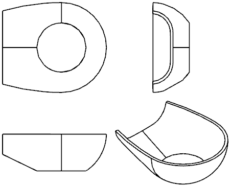 | Figure 2.1. Product structure diagram |
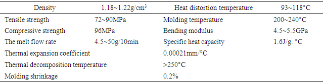
Table 2.1. 1ABS performance parameters
 |
| |
|
2.1. Equal Section Conformal Cooling Channel
The traditional conformal cooling channel is equal section according to the structural characteristics of the product and mold. Its layout is shown in Figure 2.2. The size parameters of the channel are shown in Table 2.2. 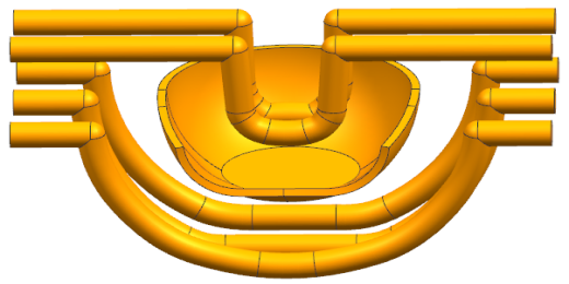 | Figure 2.2. The layout structure of the equal section conformal cooling channel |
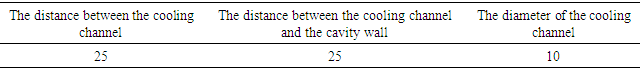
Table 2.2. Dimensional parameters of conformal cooling channel (Unit: mm)
 |
| |
|
2.2. Corrugated Conformal Channel
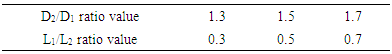
According to the existing research results, the wave height and wavelength of the corrugated channel have significant influence on heat transfer and flow. The corrugated channel diameter is 10mm, as a new heat transfer enhancement of heat transfer components. In this paper, a combination between corrugated channel and injection molding channel is taken as an innovation point. Three-dimensional model is shown in the fig 2.3, and the main structural parameters are based on channel diameter D1, peak diameter D2; non-peak arc length L1, peak arc length L2. According to a large number of experimental studies, the total heat transfer coefficient reached the highest value as the objective function. The optimum size of the corrugated channel is obtained as follows: D2/D1=1.25~1.8; L2/L1=0.2~0.7. Table 2.3. D/d ratio parameter table
 |
| |
|
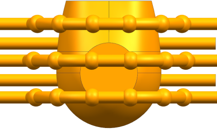 | Figure 2.3. Three-dimensional model |
3. A Method of Heat Transfer Enhancement Solution
3.1. The Steps of Solution
In this paper, the simulated fluid is incompressible steady-state flow, and the separation solver is selected with three-dimensional steady-state calculation. The operating environment is based on a standard environmental pressure, and the standard k-ε model is chosen without consideration of gravity. At the same time, the wall processing method for enhancing the wall function is adopted. The steps for solving the problem by fluent are shown in Figure 3.1.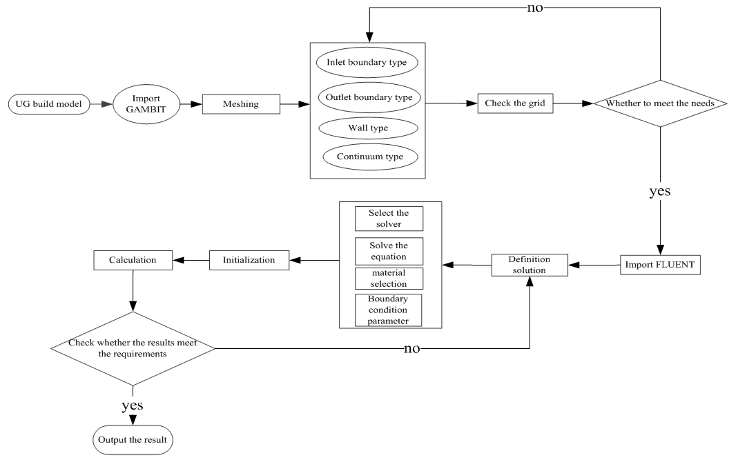 | Figure 3.1. Fluent solution steps |
The boundary conditions for solving the model are shown as follows:(1) The inlet velocity of the inlet boundary condition is 0.5m/s~1m/s, and the water temperature is 25°C;(2) The export boundary condition is set to the pressure outlet;(3) The parameters between the waterway wall surface and the contacting mold wall and the parameters between the product wall surface and the cavity wall are all set as coupled wall conditions.
3.2. Heat Transfer Model
The heat transfer model is shown in Equation 3.1. 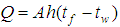 | (3.1) |
Where: Wall temperature, Unit C°;
  Fluid temperature, Unit: C°h Surface heat transfer coefficient, Unit: W/(m2•K)A heat transfer area, unit: m2The size of the surface heat transfer coefficient is related to many factors in the heat transfer process. It depends on the physical properties of the fluid, the size and the arrangement of the heat exchange surface. Furthermore, the flow rate is a key factor. The standard k-ε model k and ε equations are as follows:
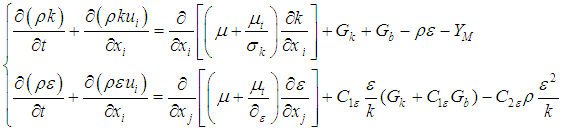 | (3.2) |
In formula (3.2), YM represents the effect on the total dissipation rate; μt=ρCμ(k2/ε); Cμ、C1ε、C2ε and C3ε are empirical constants; σk and σε are the numbers of Pr corresponding to k and ε; when the fluid is an incompressible fluid, Gb=0, YM=0. In order to facilitate the analysis of Fluent fluid software, before establishing the mathematical model, this paper simplifies the heat transfer and flow in a corrugated channel and a smooth channel by the following simplifications:(1) The fluid in the channel is incompressible and the flow in the channel is a three-dimensional steady turbulent flow;(2) The physical property parameters of the fluid are constant, and the physical property parameters do not change with the temperature;(3) The inner surface of the channel is smooth, and the fluid has no slip on the contact surface;(4) The temperature of channel wall is constant, ignoring the channel radiation heat dissipation. (5) Ignoring the influence of gravity. The control equations include the mass conservation equation, the momentum conservation equation and the energy conservation equation. The corresponding descriptions of these three equations are as follows. Mass conservation equation: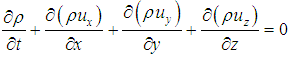 | (3.3) |
Where ρ is the density; t is the time; ux, uy, uz are the velocity components of the velocity vector in the x, y and z directions, respectively. Momentum conservation equation: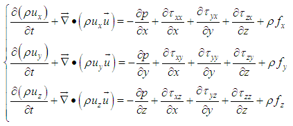 | (3.4) |
In the above formula, p is the pressure;  and
and  are components of the viscous stress
  and
and  are respectively the unit mass forces in three directions. If the mass force is only affected by gravity, axis vertical upward, then
 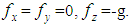 Energy conservation equation:
 | (3.5) |
4. Results and Discussion
In this chapter, the heat transfer performance and the resistance performance of various corrugated channel are simulated, compared with the equal cross-section channel. Finally, the results of the simulation are analyzed. In this paper, the distributions of temperature field, velocity field and pressure field are studied under the same conditions, and the principle of enhancing the heat transfer performance and flow resistance in the corrugated channel is preliminarily obtained.
4.1. The Distribution of Temperature
The temperature field distribution of corrugated cooling product is shown in Figure 4.1.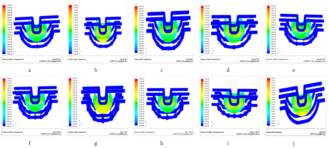 | Figure 4.1. The temperature field distribution of corrugated channel product |
Figure 4.1(a~i) and j respectively shows the distribution of temperature field of corrugated pipe and constant section channel products. Fig4.1(a~c) presents the structural parameters are D2/D1=1.3, and L1/L2 is a variable. It is found that the temperatures of Fig4.1a and Fig4.1c are higher, of which the highest are respectively 335k and 331k, and the temperature between the product and the waterway are 45k and 401k respectively; The effect of Fig4.1b heat transfer is significantly better than Fig4.1a and 4.1b; Fig4.1(g~i) shows the structural parameters are D2/D1=1.7, and L1/L2 is a variable. From the distribution of the temperature field, the temperature distribution is similar to that in Fig4.1(a~c), just because the value of D2/D1 is different, which causes the certain differences of temperature. However, Fig4.1(d~f) presents the structural parameters are D2/D1=1.5, and L1/L2 is a variable; Compared with the other two categories, the corresponding maximum temperature is significantly lower; For D2/D1=1.5, L1/L2=0.5, this parameter structure can be clearly seen from the distribution of the temperature field. It has a maximum temperature of 322k, an internal temperature of 393k and a temperature difference of 29k. It is clear to see that has a better cooling effect compared to the other groups. However, the equal cross-section channel in Fig4.1j is served as the control group, which has the worst heat transfer effect compared to the other groups with corrugated channel. Therefore, the temperature field distribution can be shown that when D2/D1 is a fixed value, L1/L2 = 0.5, this structure has better heat transfer effects. It can be seen from the temperature field distribution of the graphs ((a,d,g), (b,e,f), (c,f,i)) that the ratio of L1/L2 is constant, and D2/D1 are the changeable values. There are comprehensive comparison among these three groups. Taking the first group as an example, we can see that when L1/L2 is constant and D2/D1=1.5, the maximum temperatures of Fig4.1 a and g are 330k and 329k, respectively. However, from fig4.1d we can see that the temperature is significantly lower than the other two values, and the temperature difference is also slightly smaller. The results of the other two groups are similar to the first group. Due to the different structural parameters of the D2/D1 corrugated channel, D2/D1 also has some effects on heat transfer when the L1/L2 ratio is fixed.
4.2. The Distribution of Velocity
The cooling channel velocity field distributions are shown in Figure 4.2.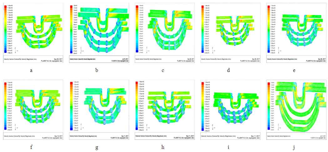 | Figure 4.2. Temperature distribution of corrugated conformal cooling channel |
Fig4.2(a~i) and j respectively shows the distribution of velocity fields of corrugated and constant section watercourse products. It can be seen from Fig.4.2j that although the flow velocity of water in the constant cross-section water channel decreases along the direction of the cooling water channel, the flow velocity in the water channel does not change much since the flow of fluid in smooth constant cross-section water channel is relatively steady. The flow velocity is about 0.6~0.8m/s. Moreover, the flow in the smooth equal cross-section water channel is relatively smooth, and the velocity of the fluid is flat along the direction of the fluid flow doesn’t have obvious changes in the speed direction. Fig4.2(a~i) shows the flow velocity distribution harbors different structural parameters of corrugated conformal channel. Compared with Fig4.2j, the gradient of the fluid velocity in the corrugated channel is more obvious during the flow process, and the fluid velocity at the peaks of the corrugated channel decreases sharply. So the corrugated channel aggravates the fluid disturbance. In this paper, we intercept the corrugated channel velocity vector with parameters of D2/D1=1.5 and L1/L2=0.5, and the corrugated convex part has been partially enlarged, as shown in Figure 4.3. It helps us to clearly observe the flow pattern of the water flow in the corrugated channel. The direction of the flow velocity of the fluid in the equal cross-section channel is parallel to the flow direction of the fluid. Moreover, the distribution of the fluid flow rate is flat, so the fluid in the channel can not disturb the boundary layer very well so that the heat can not be effectively transmitted. Compared with the smooth equal section channel, the convex wall of the corrugated channel leads to the flow of the fluid, and has disturbance to the fluid at the same time. Therefore, the fluid inside the corrugated pipe water channel is bigger than the constant cross-section: the separation and subsequent attachment of the fluid to the boundary layer, the fluid at the near-wall surface appears as a vortex on the water-wall surface due to the disturbance of corrugations. In the process of continuous separation wall, fluid flow attached itself to the wall and rotated itself to enhance the thermal boundary layer perturbation. Furthermore, it also increased the boundary layer due to the destruction of the thinning process, which is conducive to heat transfer through the boundary layer. This is the reason why the heat transfer enhancement effect of the corrugated pipe is better than that with the constant cross section waterway. 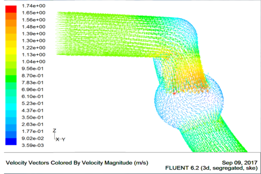 | Figure 4.3. Local speed vector |
4.3. The Distribution of the Pressure Drop
The distribution of the pressure drop along the conformal cooling channel is shown in Figure 4.4. 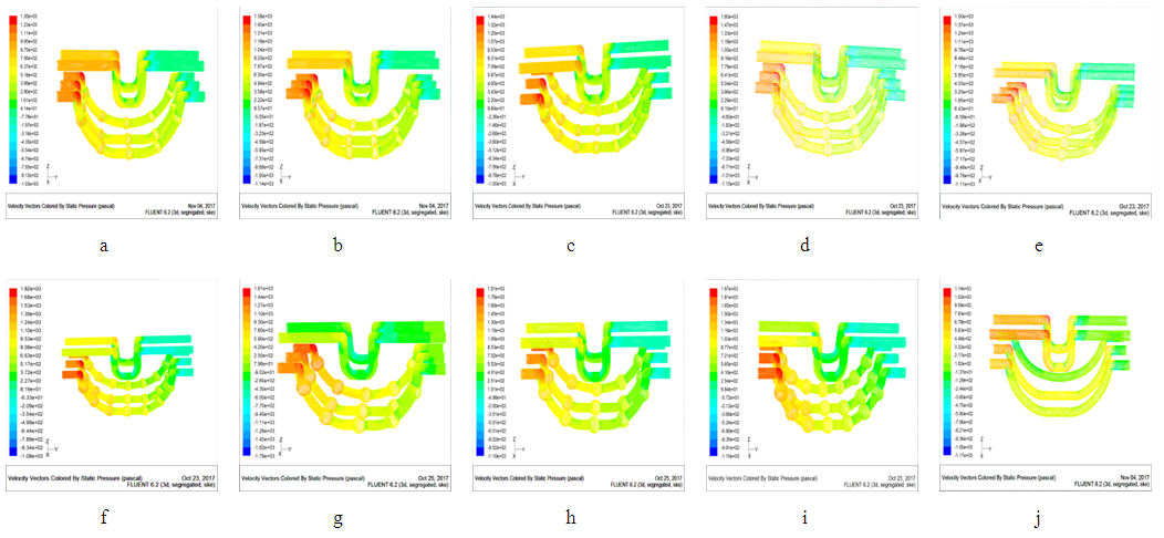 | Figure 4.4. Distribution of pressure drop in corrugated conformal cooling channel |
Fig4.4 shows the pressure field distribution of corrugated channel and equal cross-section channel. By analyzing and comparing these three sets of data ((a,d,g), (b,e,h), (c,f,i)), we can see that when L1/L2 is constant and D2/D1 is increasing, the pressure drop in the corrugated channel also increases. This is because the fluid is obstructed by the corrugated protrusions, so that the flow of the fluid in the tube is not easily performed. By analyzing and comparing these three sets of data ((a,b,c), (d,e,f), (g,h,i)), we can see that when D2/D1 is constant and L1/L2 is increased, the pressure in the channel has been reduced; However, because of the magnitude of the pressure, such small changes can not be numerically reflected. By comparing and analyzing the pressure drop distribution of corrugated channel and equal cross section channel, it can be found that there is a significant pressure change along the axial direction of the channel from inlet to outlet. The pressure distribution of the fluid in the equal cross-section water channel is relatively uniform, and the pressure difference of the fluid from the inlet to the outlet is relatively small. However, the pressure distribution in corrugated channel is very uneven. The pressure changes in the corrugated channel along the inlet to the outlet are larger and more obvious than that of the equal cross section channel. Because the corrugated channel wall has corrugated convex, it will make the fluid in the corrugated convex generate swirling flow, thus increase the flow resistance. It leads to the loss of resistance to increase, which causes the pressure to change.
4.4. Analysis Results
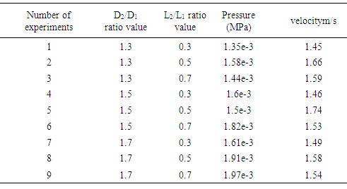
In this paper, we use the Fluent software to simulate the cooling of nine different design variables, and obtain the temperature distribution range, pressure drop range and fluid flow velocity range after the stabilization. The results are shown in Table 4.1. Table 4.1. Experimental Design and Simulation Results
 |
| |
|
The distribution of temperature and the distribution of water velocity and pressure drop distribution are obtained by simulation. Corresponding temperature curves, water velocity curves, and pressure curves are obtained, as shown in Fig 4.5~4.7. It can be seen from the temperature curve shown in 4.6 that the temperature curve is at the lowest point when D2/D1 is constant and L1/L2=0.5. Therefore, when L1/L2=0.5, it is most favorable for heat transfer. In the three curves, when L1/L2 is constant and D2/D1=1.5, the overall temperature curve is the lowest, so when D2/D1=1.5, the heat transfer is most favorable. Similarly, according to the curve of water velocity in Figure 4.6, we can see that when D2/D1 is constant and L1/L2=0.5, the overall water flow in the channel is higher. When L1/L2 is variable, D2/D1 =1.5, the overall flow velocity curve is higher. According to Fig 4.7, when D2/D1=1.3, it can be seen from the curve that as the ratio of L1/L2 changes, the pressure change is not very large and the pressure drop is relatively small, which means that the change of water flow velocity in the waterway is not so fierce. When D2/D1=1.5,L1/L2 ratio from 0.3 to 0.5, the curve is relatively flat. However, the ratio of L1/L2 from 0.5 to 0.7, the pressure significantly increases; however, when D2/D1=1.7, the pressure is significantly higher than the other two curves, and the flow of water is significantly obstructed. It can be concluded that the corrugated conformal channel has a higher heat transfer effect than that of equal cross section, and the structural parameters of various corrugated channel have different effects. When D2/D1=1.5,L1/L2=0.5, the overall heat transfer cooling effect is the best. 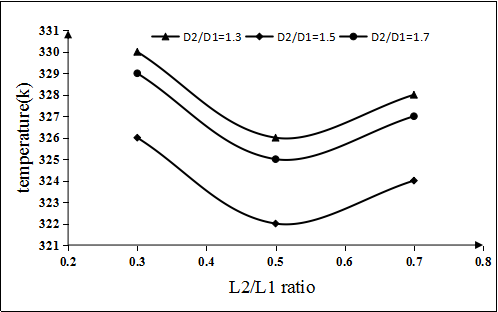 | Figure 4.5. Temperature curve |
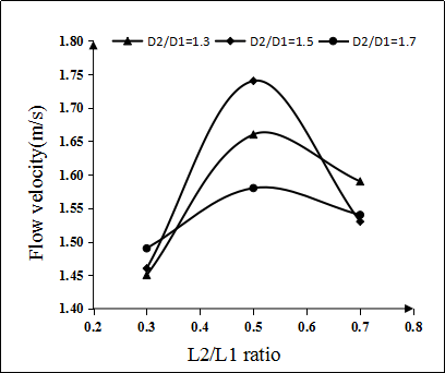 | Figure 4.6. Flow velocity curve |
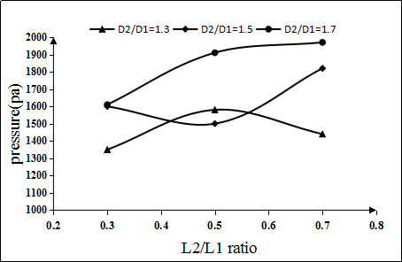 | Figure 4.7. Pressure curve |
4.5. Heat Transfer and Resistance Performance Test and Analysis
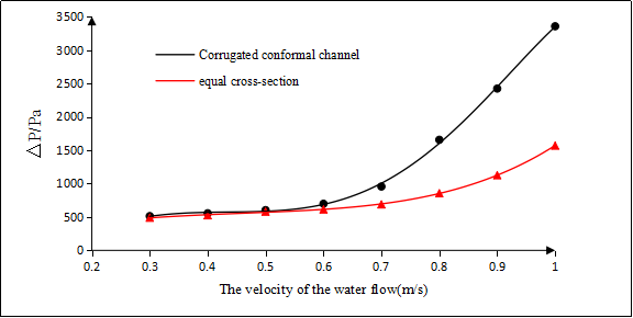
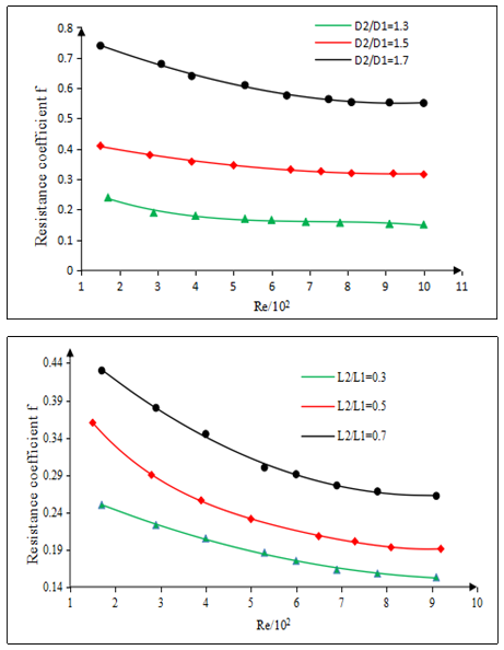
In this paper, we choose the optimized corrugated channel and smooth equal cross-section channel for testing. As shown in Fig.4.8 and Fig4.9, The graph of the heat transfer coefficient and the pressure drop ΔP is obtained from the data. It can be seen from the figure that the corrugated channel enhances the heat transfer and increases the resistance within the experimental water flow rate range. In the flow (0.1m/s~0.5m/s), with the increase of velocity, the ratio of heat transfer coefficient between corrugated channel and smooth equal cross-section water channel is about 1.36~2.93, and the pressure drop ratio is about 1.05~2.14. Fluctuations in the corrugated channel make the original longitudinal flow form a vertical flow pattern, which makes it easy to reach the turbulent flow condition, thus enhancing the heat transfer. According to the resistance coefficient at the same flow rate, it can be seen that the resistance coefficient f of the corrugated channel is much larger than that of the smooth equal channel at the same flow rate or the same Re. This shows that the pressure loss of corrugated channels is greater under the same condition. This is caused by improving the heat transfer performance of corrugated channel. Therefore, while paying attention to the enhanced performance of the corrugated waterway, this study should also pay attention to the size of the pressure drop in the channel. The advantages and disadvantages between corrugated channel and smooth equal cross section must be taken into consideration. In order to accurately predict the resistance coefficient, this paper uses statistical correlation to calculate the resistance coefficient. As shown in Figure 4.10, the resistance coefficients of corrugated channel are shown for the structural parameters of the two variables. No matter what the structure of corrugated waterway, with the increase of flow rate, the resistance coefficient shows a downward trend. When the flow rate is small, the change of flow rate has a greater influence on the resistance coefficient. When u<0.6m/s, it can be seen from this curve graphic that the resistance coefficient curve shows a more decline than the slope. When u>0.6m/s, the curve changes remain relatively steady. 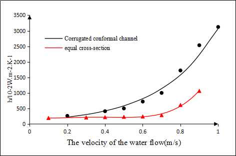 | Figure 4.8. Heat transfer coefficient comparison chart |
 | Figure 4.9. Pressure drop comparison chart |
 | Figure 4.10. Relationship between resistance coefficient and Re |
5. Case Analysis Results
Two sets of molds with different cooling systems are respectively designed and manufactured, as shown in Figure 4.11a), which is a mold cavity physical with a traditional conformal cooling water channel. Figure 4.11b) shows the mold cavity with corrugated cooling water channel physical. Two sets of molds have been assembled one after the other, and then they are mounted on the injection molding machine for injection molding production and test molds respectively. The injection molding machine for molds and test molds are shown in Figure 4.12. 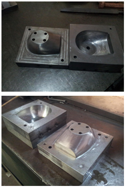 | Figure 4.11. a) Mold core with the traditional conformal cooling water channel; b) Mold core with corrugated conformal cooling water channel |
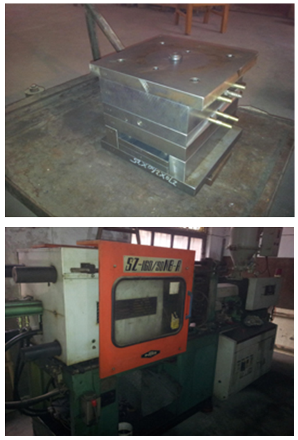 | Figure 4.12. Mold and injection molding machine |
Fig4.13 shows a plastic product made from two sets of molds, of which the left is the mold of the conventional conformal cooling system and the right is the mold of the corrugated cooling system. In order to be able to detect the differences between warpage of two products and prototype of the product. As shown in Fig4.14, two products are scanned by using the Nika Minolta Non-Contact 3D Scanner RANGE7. Then the scanned point cloud is imported into the Mastercam software to analyze the warpage of the product. Finally, the dimensional accuracy of the product analyzed by software is shown in Fig4.15. 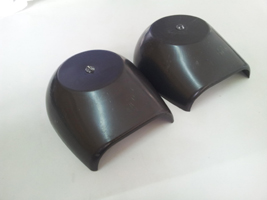 | Figure 4.13. Plastic products |
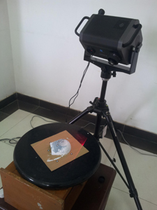 | Figure 4.14. The 3D Scanner scans the product |
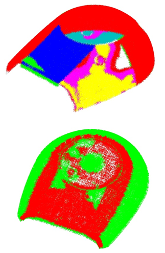 | Figure 4.15. Deformation analysis of the product |
The results show that the cooling uniformity of conformal cooling water channel is better, which is also the reason of the smaller warpage deformation of injection-molded parts obtained by conformal cooling injection molding.
References
| [1] | Nogueira, A. A., et al. "A new way to produce conformal cooling channels by RPT for moulding blocks of the hybrid moulds." PMI 2010 - Int. Conf. on Polymers & Moulds Innovations PMI 2010 - Int. Conf. on Polymers & Moulds Innovations 2010: 127-130. |
| [2] | Mohamed, Omar A., S. H. Masood, and A. Saifullah. "A Simulation Study of Conformal Cooling Channels in Plastic Injection Molding." International Journal of Engineering Research 2.5 (2013): 344-348. |
| [3] | Chen, Yao, et al. "Numerical simulation of enhanced heat transfer mechanism in sinusoidal corrugated tubes." Journal of Nanjing Tech University (2014). |
| [4] | Liu, Jia Ju, and L. Wei. "A Numerical Study on Heat Transfer of Three-Start Spirally Corrugated Tubes." Journal of Engineering Thermophysics 34.11 (2013): 2128-2131. |
| [5] | Xiao, J. H., C. F. Qian, and Z. X. Huang. "Study of effects and mechanisms of heat transfer enhancement of corrugated tubes." Chemical Engineering 35.1(2007): 12-15. |
| [6] | Dang, Gao Jian, et al. "Enhancement of boiling heat transfer in corrugated tubes." Chemical Engineering 36.13 (2008). |
| [7] | Wu, Feng, and W. Zhou. "Numerical simulation and optimization of convective heat transfer and pressure drop in corrugated tubes." Heat Transfer Research 43.6 (2012): 527-544. |
| [8] | Bo, X. U., and D. Y. Feng. "Study on enhancement of heat exchanger with transverse bellows." Journal of University of Shanghai for Science & Technology (2004). |
| [9] | Au, K. M., and K. M. Yu. "Conformal cooling channel design and CAE simulation for rapid blow mould." International Journal of Advanced Manufacturing Technology 66. 1-4 (2013): 311-324. |
| [10] | Dimla, Dimla E. "Design Considerations of Conformal Cooling Channels in Injection Moulding Tools Design: An Overview." 7(2015): pp: 627-635. |
| [11] | Xiao, Jin Hua. "Study of Fluid Flow and Heat Transfer in Corrugated Tubes." Journal of Beijing University of Chemical Technology (2006). |
| [12] | Saifullah, A. B. M., and S. H. Masood. "Finite Element Thermal Analysis of Conformal Cooling Channels in Injection Moulding." Proceedings of the 5th Australasian Congress on Applied Mechanics Engineers Australia, 2007: 337-341. |
| [13] | Barba, A., S. Rainieri, and M. Spiga. "HEAT TRANSFER ENHANCEMENT IN A CORRUGATED TUBE." International Communications in Heat & Mass Transfer 29.3 (2002): 313-322. |
| [14] | Chen, Juin, H. Müller-Steinhagen, and G. G. Duffy. "Heat transfer enhancement in dimpled tubes." Applied Thermal Engineering 21.5 (2001): 535-547. |
| [15] | Bergles, A. E. "Heat Transfer Enhancement— The Encouragement and Accommodation of High Heat Fluxes." Journal of Heat Transfer 119.1(1997):8-19. |
| [16] | Bergles, Arthure. "Heat Transfer Enhancement", "The Maturing of Second-Generation Heat Transfer Technology." Heat Transfer Engineering 18.1(1997):47-55. |
| [17] | Naidek, Bruna P., et al. "Experimental analysis of horizontal liquid-gas slug flow pressure drop in d-type corrugated pipes." Experimental Thermal & Fluid Science 81(2017): 234-243. |
| [18] | Xiang, X M, et al. "Finite element analysis and experimental study on a bellows joint." Engineering Structures 151 (2017): 584-598. |
| [19] | Wang, Jiansheng, et al. "Numerical and experimental investigation of pulsating heat pipes with corrugated configuration." Applied Thermal Engineering 102 (2016): 158-166. |
| [20] | Tan, Yu Fei, and J. X. Chen. "An Experimental Study of the Performance of Novel Stainless Steel-made Corrugated Tubes and Their Intensified Heat Transfer." Journal of Engineering for Thermal Energy & Power 18.1 (2003): 47-49. |
| [21] | Wang, Yu, et al. "Automatic design of conformal cooling circuits for rapid tooling." Computer-Aided Design 43.8 (2011): 1001-1010. |

 Abstract
 Reference
 Full-Text PDF
 Full-text HTML