Arash Bahrami , Hossein Shokouhmand
School of Mechanical Engineering, College of Engineering, University of Tehran, Tehran, Iran
Correspondence to: Arash Bahrami , School of Mechanical Engineering, College of Engineering, University of Tehran, Tehran, Iran.
| Email: |  |
Copyright © 2017 Scientific & Academic Publishing. All Rights Reserved.
This work is licensed under the Creative Commons Attribution International License (CC BY).
http://creativecommons.org/licenses/by/4.0/

Abstract
In this paper, we investigate asymmetrical oscillation of a single bubble inside a tubular rigid blood vessel and evaluate impacts of ultrasonic pressure field under which the bubble is stimulated and takes the shape of an ellipsoid from a sphere. CFD results show that whatever the ratio of the radius of bubble/vessel diameter increases the asymmetric behaviour of the bubble and the pressure exerted on the blood vessel wall go up. Moreover, similar results are obtained by higher amplitude coefficients of the ultrasonic pressure field on the vessel wall. Such results can be of high importance in the clinical injuries caused by asymmetric effects of the bubbles inside vessels especially in cases for elder people and little children who have thinner or weaker blood vessels. Finite Volume Method - SIMPLE Algorithm has been used in order to implement CFD operation. For this purpose, it is necessary to generate an initial smooth grid domain using Delaunay's Method with Laplacian Smoothing approach and afterward, modify the quality of the new grids in each time step. For the area near the bubble, total re-meshing is required to avoid overly skewed grids due to relatively more intense movements of the bubble’s surface. Also, we use Local-time-derivative based approach which is a novel method to deal with the moving grids in unsteady problems.
Keywords:
Bubble oscillation, Ultrasonic pressure, Finite Volume Method, Moving boundary
Cite this paper: Arash Bahrami , Hossein Shokouhmand , Numerical Study of Asymmetrical Oscillation of a Bubble inside a Rigid Blood Vessel under Ultrasonic Pressure Using CFD, SIMPLE Algorithm, American Journal of Fluid Dynamics, Vol. 7 No. 2, 2017, pp. 49-55. doi: 10.5923/j.ajfd.20170702.02.
1. Introduction
Micro-bubbles are expanded and contracted with each pressure cycle to respond to an ultrasonic pressure wave. The optical picturing method has been used and developed [1], in order to visualize the increase and decrease of bubbles diameters, that the diaphragm (camera) records the bubble oscillations with high speed from Nano-second degree by two-dimensional pictures of micro-bubbles. For example, the bubble oscillation is almost equi-phase and analogous with the frequency of exerted pressure for a micro-bubble with diameter about 2 µm in a relatively weak ultrasonic pressure field, but with the increase in the intensity of ultrasonic pressure field, the amount of expansion and also the speed of bubble collapse are also increased and the micro-bubble oscillation takes a nonlinear behavior unto the pressure exerted on it [2]. Also, greater volume change of the bubble causes it to collapse and be parceled off with more powerful ultrasonic pressure field (due to the nonlinear behavior of the bubble). As a result, the frequency of a reflected spectrum which radiates from the bubble, is several times more than the exerted frequency and sometimes is a fraction of the exerted frequency [3]. These harmonic reflected frequencies are used to find the existence or concentration of bubbles in the body. The results recorded from the reflection radiated from the bubble indicate that the frequency of reflective waves is increased when the bubble is disappeared and parceled off after vast oscillations, but on the other hand the power of these waves is decreased. The results of research conducted on micro-bubbles with lipid coating indicate that with the increase in the power of exerted pressure, decreasing its frequency and also lessening the initial diameter of the bubbles, their expansions and also collapses increase [4]. The bubble collapses asymmetrically and the created fluid jet can lead to incur damage on the septum with oscillations of a bubble close to a boundary such as a vessel wall (live tissue) [5]. The waves reflected off the bubbles in response to the frequency, amplitude and phase of ultrasonic pulse are very different from the body’s tissues’ wave reflections, due to the changes arising from the speed and acceleration of the bubble surface. The proper strategic design for imaging from the bubble includes not only the parameters such as selection of frequency, band width and exerted pulse pressure, but also a design of a group of several pulses that these parameters are corrected by them to ease the distinction between the reflections from bubbles and the reflections from tissues. The bubble imaging at the beginning was accomplished based on the harmonic reflections from each pulse [6]. Each reflection is filtered after reception by this technique to eliminate the frequencies out of harmonic band. Concerning the harmonic strategy, a pulse with narrow band width is sent for decreasing the overlapping of radiated and received spectrums of pulses. A better method was created later for picturing which utilized the group of pulses with corrected phase or amplitude for sending the waves [6]. The reflection of living tissues is eliminated, in collection of reflected waves in a manner, while the sensitiveness to the bubbles reflections still remains effectively. The merit of exploiting this group of pulses is to obviate the need for filtering which has used in primary methods.From the physical perspective, prediction of ultrasonic parameters such as intensity, frequency, band width and rate of pulses repetition is very important to achieve high-precision and appropriate results of the bubbles’ applications. Micro-bubbles are good-absorbent and good-repulsive for the ultrasonic energy. Development of strategies which lead to increase the energy absorption by bubbles, does have much value. Therapeutically, such energy in the aim of targeting particular blood vessels can be very useful; due to this fact that it causes the decrease of the destruction danger in tissues in other parts of the body. Diagnostically, this energy can be a potential for improving the sensitiveness of imaging from blood flow in small vessels. When a bubble is stimulated under its resonance frequency, it absorbs and reflects higher energy from its surface [7]. According to these researches [7], this result showed that limiting the bubbles inside a finite environment leads to lessen its resonance frequency than its state in an infinite environment. Also, its resonance frequency becomes less and less with the increase in the bubble radius and also decrease in the enclosing vessel radius.Shock Wave Lithotripsy (SWL) for example, can be mentioned as other bubbles’ applications, therapeutically. SWL is the most certain and effective possible method for the stones smaller than 2 cm, according to the existing evidence. In this method, cavitation bubbles (bubbles arising from the decrease of pressure) are created with the generation of the first radiated shock wave (pressure wave). These generated bubbles are expanded and then, disappeared so quickly that the fluid jets break the stones up and make them to grind, as the result of the bubbles collapses in each cycle. However, some damages on small vessels, capillaries and tissues have been observed in this approach [8]. Understanding the mechanism and features of bubble oscillation is of paramount importance to decrease the negative effects of SWL.All such biological factors and phenomena necessitate the cognition of the characteristics of the bubble, and factors influencing its movement and oscillation. Recently, Zhong et al. [9] have done tests on the bubble dynamics during the process of exertion of ultrasonic periodic pressure inside the vessel. Their observations indicate that the limited expansion of bubbles inside the vessel and in consequence and also, remarkable dilation of vessel wall as the result of asymmetry oscillation of the bubble can lead to tear and rupture the vessels with small diameter. They have modeled the radial oscillation of a spherical bubble without considering the wall to understand the reciprocal effect between bubble and wall and also stated that this modeling isn’t proper for correct study of the bubble oscillation in an environment like a tube. Also, Prosperetti [10] and Risso [11] have studied the linear disorders of the spherical surface modes by decoupling the radial and shape oscillations and letting each one to evolve independently. They pointed out that the reciprocity between the radial modes and volumetric oscillations doesn’t follow the model of the bubble large collapse velocity. Proper models which represent the asymmetric oscillation of the bubbles enclosed by boundaries are still under research and development. Recently, Hu et al [12] have represented a model for the asymmetric oscillation of a bubble inside a rigid (fully stiff under stress) micro-vessel in which the ratio of the radius of the vessel is remarkably large, comparing the radius of the bubble. This model indicates that the asymmetric oscillation leads to exert significantly higher pressure on the vessel wall than what the Rayleigh-Plesset solution predicts. Also, Qin et al [13] studied the effect of elastic vessel wall on the bubble oscillation in a non-viscous fluid. Shima et al [14] conducted research on bubble oscillation inside a viscous space between two flat plates and studied the effects of two infinite walls on the bubble oscillation. Now, in this paper, we have attempted to study the asymmetric oscillation of a bubble and then the parameters affecting the bubble oscillation such as the bubble radius and the vessel radius, with the assumptions that the vessel wall is rigid, the fluid surrounding the bubble is Newtonian viscous and the gas pressure inside the bubble remains uniform. Finally, we study the oscillation impacts on the vessel wall and the pressure exerted on it.
2. Governing Equations
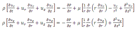
To study the asymmetric oscillations of a bubble inside a liquid-filled rigid (inflexible and avoiding deformation) micro-vessel, it is considered that in the first instance, the bubble has a spherical shape with radius of a0 inside a vessel with radius of R0 with a length of 2L. The bubble is exactly at the center of the tubular vessel and according to the Fig.1, axis z is the cylindrical symmetry axis and the axis r is in the perpendicular direction on it in line with the radius of the vessel. The mass conservation and the momentum for the incompressible and viscous fluid lead to the following three equations in the cylindrical coordinate system governing the radial and axial components, ur and uz, the velocity and the pressure of p: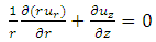 | (1) |
 The fluid around the bubble is assumed Newtonian, incompressible with dynamic viscosity of 1.23e-3 Pa.s and density of 1059 kg/m3 and we select a polytrophic gas with k=1.4 for the gas inside the bubble, namely, the equation governing the behaviour of gas inside the bubble, as follows:
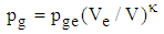 | (2) |
In which Pge and Ve refer to the pressure and volume inside the bubble, respectively, at a reference state.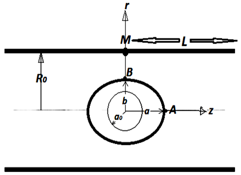 | Figure 1. A schematic for the bubble–vessel system, in which the bubble is initially spherical with a radius a0 and evolves into a revolving ellipsoidal with major and minor axes, a and b, inside a vessel with the radius of R0 and length of 2L |
2.1. Boundary and Initial Conditions
Considering the fluid around the bubble, we assume that the fluid is stationary, initially and the initial pressure of P0=P*0+Psb is assumed for the pressure inside the bubble, at the atmospheric pressure of P*0=101kPa plus gauge pressure inside the vessel (Psb=15 kPa), namely. It is expected that the liquid far from the bubble remains undisturbed, with assumption of long tubular vessel usually for L/R0 ≥10 so that uz=0. In addition, with the assumption of no-slip condition, and the incompressibility for the bubble’s surrounding fluid and regardless of viscosity of gas inside the bubble, under the condition that the bubble surface evolves into an ellipsoid with z-axis as its cylindrically symmetrical axis, we have the pressure boundary condition on the bubble surface as follows: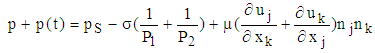 | (3) |
In which n is normal vector on the surface, and σ is the surface tension which is taken to be σ=56e-3 N/m, and ρ1 and ρ2 are as the radius of curvature of the bubble in each point on its surface and their quantities can be computed by regarding the following equations: | (4) |
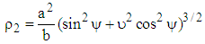 | (5) |
In above equations, υ=b/a, a is the main axis of ellipse and b is its radial axis according to the Figure 1. Also, ψ in above equations is a real parameter for ellipse which is obtained with regard to the equations of r=bsin(ψ) and z=acos(ψ). The ultrasonic pressure of P(t) from the time of t=0 till t=1/(2f) on the bubble surface is exerted, as follows: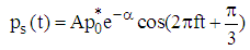 | (6) |
In which A=25 is the pressure amplitude coefficient and f=100 kHz which is the frequency of exerted shock wave. Moreover, it is assumed that the speed of the bubble surface is equal to the speed of the liquid fluid on the bubble surface.
3. Mesh Generation and Movement
It is necessary the calculations to be solved on a proper mesh, after discretization of the conservation equations governing the fluids flow dynamics. The type of mesh and its quality are essential for the accuracy of the solution and the precision of results, as in the case of improper mesh, any sort of discretization of equations with any order of precision would not result in sensible and applicable responses for the intended problem. In this paper, owing to the complex geometry of the problem, unstructured triangular grids are generated by Delaunay's Method [15] which conform and fit to complex kinds of geometries and provide the intended precision. Afterwards, the generated unstructured triangular mesh needs some kind of smoothing approach to generate a regular and efficient mesh. Therefore, Laplacian Smoothing Method [16] has been utilized in order to obtain the ideal mesh with high quality. The sides of triangles are considered as springs in Laplacian Method, and these springs at any time are balanced to establish a static balance of forces for each node among its neighbouring nodes that are connected to it. A force which is exerted by each spring, is proportional with the length and direction of the node and its neighbour. Therefore, the total forces which are exerted by all springs connected to the node, as follows: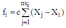 | (7) |
Where, C is the fixed arbitrary coefficient of spring and Xi is the coordinate of nodes. A sample of the mesh generation by Delaunay's Method after exerting Laplacian Smoothing, has been shown in Fig. 2.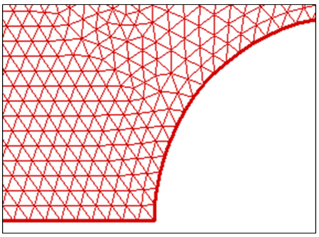 | Figure 2. A sample mesh generated by Delaunay's Method after Laplacian Smoothing |
3.1. Grid Movement
In many practical situations the fluid interacts with rigid or flexible bodies. This interaction results in changes of the fluid-flow domain caused by the body motion, like the flow in cylinder driven by a piston [17]. In such cases it is necessary to solve the flow equations on a moving grid. In this case, we use Local-time-derivative based approach which is a novel method for treating moving grids. The idea of this method is to compute the flow on a moving grid by solving the same equations as for a stationary grid (Eulerian formulation of equations presented in equations number (1). Since the fully implicit method for integration in time is used, the fluxes and source terms in the governing equations are evaluated using solely the solution form the current time step. No data about the grid from previous time steps are needed, i.e. we do not have to know where the grid was and what shape the CVs had. This fact enables us to ignore the grid motion and to solve the governing equations in the usual way as for a stationary grid. The old solutions appear only in unsteady term which is represented by the local time derivative expressing the rate of change at a fixed point in space – the new position of CV centre. In order to approximate the unsteady term, it is necessary to use the variable values from one or two previous time steps (depending on the time integration scheme) at the new grid position. For the mid-point rule approximation of the volume integrals, only the old values at the new position of CV centre are needed. These values can be obtained by interpolation. In principle any kind of interpolation can be used. Generally, the interpolation process consists of finding of sufficient number of donor points required for construction of interpolation functions and calculation of weighting factors. The main part of the interpolation process is the searching for donor points. If the grid topology does not change, the interpolation procedure is significantly simplified, since the donor cells need to be sought in the immediate neighbourhood of the corresponding cell, whose old position is known. One possibility to obtain the old value at the new CV centre is the following linear interpolation: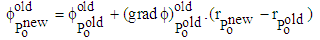 | (8) |
where,  stands for the transported variable and superscripts old and new denote the old and new solution or position respectively (figure 3).
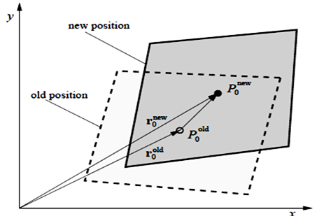 | Figure 3. Old and new positions of a control volume between two consecutive time steps |
The gradients of old variables are calculated at the old grid. Note that this interpolation can be used only if the grid does not change its topology while moving, i.e. if every cell has its old counterpart. Furthermore, it is desirable that the grid does not move significantly which is usually the case due to accuracy reasons. If the grid changes its topology, when for example re-meshing is made, equation (8) can still be used, but instead of point P0old one needs to find the nearest point at the old grid.
4. Solution Procedure
The segregated algorithm adopted in this work is the Simple algorithm [18, 19] which involves a predictor and a corrector step. In the predictor step, the velocity field is calculated based on a guessed or estimated pressure field. In the corrector step, a pressure (or a pressure-correction) equation is derived and solved. Then, the variation in the pressure field is accounted for within the momentum equations by corrections to the velocity field. Thus, the velocity, and pressure fields are driven, iteratively, to better satisfying the momentum and continuity equations simultaneously and convergence is achieved by repeatedly applying the mentioned procedure. In this work the second-order three-time-levels implicit scheme [20] is used to improve the accuracy in time-stepping. In Fig. 4, the strategy adopted to deal with the mesh movement has been shown. We divide the area inside the vessel into two areas including an area close to the bubble and the other area far from it. We name the close area as the area equal to a length that is two times greater than the diameter of the initial spherical shape of the bubble with radius a0 and out of this area is named the area far from the bubble. In the area far from the bubble, the grid isn’t changed by time and remains fixed. But, in the area close to the bubble, meshing is changed by time, in the way that if P is a point on the boundary of the bubble in a particular time (according to Fig. 4) and its location moves to the point P' in the next time step, the point A which is in the area close to the bubble, must be displaced in such a way that its new location must move to the location A′. | Figure 4. The schematic illustration for new position of the new nodes A' and P' from their previous states A and P after change of grids of each time steps |
This displacement can be considered by a definition of exponential or linear function. This displacement function here is written as follows: | (9) |
Here, ∆L is equal to PP', L equals LP and Xold is equal to the lengths of LA and thus, the length of LA' is defined as Xnew.
5. Results and Discussion
To study the characteristics of asymmetric oscillations of the bubble inside the vessel, the dimensionless main axes of a/a0 and b/b0 versus time for the bubble with radius of a0= 5 µm and vessel with radius of R0= 20 µm have been shown in Fig. 5. As it is shown in this figure, the asymmetric oscillation of the bubble enclosed in the tubular domain begins from the outset and asymmetry gets greater by going to the second cycle. This phenomenon stems from the fact that the fluid is static at the first cycle, but, the fluid inertia becomes an effective factor for the intensification of the asymmetric oscillation, after the first cycle.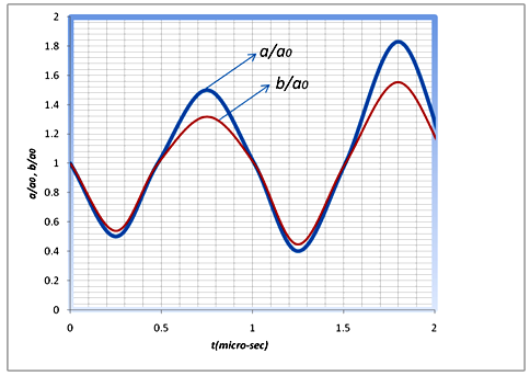 | Figure 5. The normalized major axis of the bubble a/a0 and minor axis of the bubble b/a0 versus time for R0= 20 µm |
In Fig. 6, the impact of different vessel radii with a fixed initial bubble radius a0=5 has been shown. The amplitude of the asymmetry degree (a-b)/a is increased remarkably with the decrease in the radius of the vessel, according to this figure. In fact, it is noticeable that this asymmetry degree substantially intensifies, with the decrease in the vessel radius up to R0=10 µm.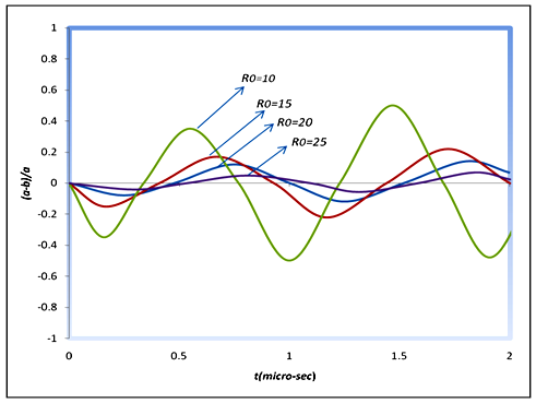 | Figure 6. Asymmetry degree of (a-b)/a versus time for different radiuses of vessels R0=10,15,20,25 |
Also, by regarding Fig. 7 in which the radius of the vessel is fixed and is equal to R0=25 µm, it is clear that the amount of asymmetry degree (a-b)/a is increased greatly, with the increase in the bubble radius in the form of a0=5, 10, 15. This result can be also found out from both Fig. 6 and 7 that generally, the amplitude of oscillations and the asymmetry degree (a-b)/a intensify, with the increase in the ratio of the bubble/vessel radius.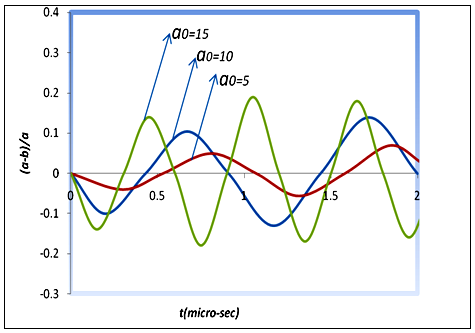 | Figure 7. Profile of (a-b)/a versus time for different bubble radiuses a0=5,10,15 |
In Fig. 8, the profile of pressure has been drawn versus time, with different radii for the vessel exerted at point M (this point has been shown in Fig.1), namely, a place that (z=0 and r=R0). This profile is based on a state in which the bubble radius is a0=5 µm and the vessel radii are R0= 10, 15, 20, and 25 µm. We know that the point M is the place where the greatest and least pressures exerted on the vessel are imposed, by regarding the references [11-13]. A comparison between Fig.5 and 8 for example, where the vessel radius is R=20µm shows the issue that the pressure at this point is corresponding with the bubble asymmetric oscillation, that is, the pressure exerted on it reaches its maximum amount, when the bubble reaches its greatest expansion; and also, the pressure reaches its minimum, when the bubble reaches its least volume. Furthermore, we can find out from this figure. that for a bubble with initial radius a0=5 that is confined inside vessels with different radiuses, the lesser the radius of the vessel, the greater the pressure exerted at the point M. In other words, the greater the ratio of the bubble/vessel radius, the greater the peak of the pressure exerted on the vessel wall at the point M, and also, the increase in this ratio leads to increase in the frequencies at which the bubble oscillates. This issue is important especially in materials mechanics that the frequency and peak of a cyclic loading are as the dominating parameter in determining the material failure. For this reason, it becomes more serious for old patients and also children who have weaker and thinner vessels, thus elaborate precaution should be taken in applying this technology for them.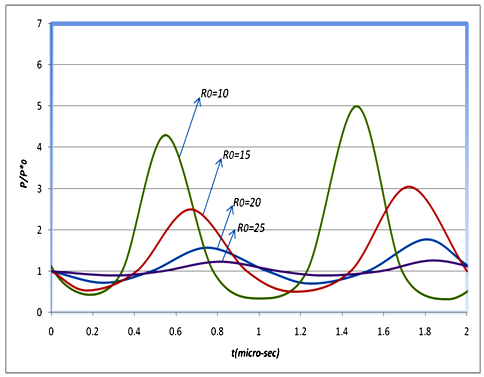 | Figure 8. The normalized pressure p/p0 at the point M for different radii of the vessel versus time |
The amplitude of ultrasonic pressure exerted on the bubble has been considered fixed and equal to A= 25 in all previous figures. Now, the change in this parameter on the asymmetry degree of the bubble, (a-b)/a0 has been specified in Fig.9. This plot has been sketched for the bubble oscillation with radius of a0= 5µm, vessel radius of R0= 20µm and the pressure amplitudes equal to A= 15, 25, 35. As it is shown in this figure, the increase in the peaks of the asymmetry degree of (a-b)/a0 becomes greater with the increase in the pressure exerted on the bubble surface. This means that more exerted energy leads to the increase in the asymmetric oscillations of the bubble. Therefore, the pressure amplitude of the shock wave has a direct and important role which can lead to the collapse of the bubble.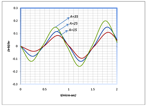 | Figure 9. The effect of the pressure amplitude on asymmetry degree of (a-b)/a0 |
6. Concluding Remarks
Interest in acquiring the cognition of the behavior of bubble oscillation drove us toward the numerical modeling of this phenomenon by the Finite Volume Method. Following this process, unstructured mesh is applied and some approaches for grid generation, smoothing, and mesh revising for the boundary movement have been taken into account. The bubble for this study has been assumed as axisymmetric and the fluid around it is as Newtonian. In this research, we have studied two-phase coupled model of liquid-gas oscillating system for obtaining the profile changes of a micro-bubble inside a micro-vessel, which is under the ultrasonic pressure field. According to the provided figures and results, this issue should be noted that with the increase in the ratio of bubble/vessel radius, the intensity of the asymmetric oscillation of the bubble substantially increases. Occurrence of this phenomenon inside the tissue of creatures is dangerous; because, whatever the asymmetric oscillation gets greater, the probability of collapsing and destruction of the bubble is increased, that in this state, the bubble jet could be formed and it would cause destruction of the tissues and the vessels. In addition, with this increase in ratio of the bubble/vessel radius and also with the increase in the amplitude of the exerted ultrasonic pressure, the pressure exerted on the sensitive point of the vessel surrounding the bubble, i.e. point M in Fig.1, is increased, due to the bubble oscillation that in fact, it can increase the probability of emergence of the vessel’s tear and bleeding. These incidents and the factors creating them should be considered in designing desirable conditions for using ultrasonic technology. Extensive complementary works can be done for the promotion of this field at higher levels. The vessel wall can be examined elastic or viscoelastic and the impact of oscillation on vessel can be studied more realistically. Also, the bubble can have coating and even the gas inside the bubble can be entered into the numerical analysis, and also the viscosity effects of the gas can be involved in computations. Furthermore, by regarding this issue that usually, a group of bubbles enter the body, the oscillation and the mutual effect of two or several bubbles which are in vicinity of each other, can be studied.
References
| [1] | D. Cosgrove, C. Harvey. ‘Clinical uses of microbubbles in diagnosis and treatment’ Med. Biol. Eng. Comput., 47 (8) (2009), pp. 813-826. |
| [2] | Bloch S H, Wan M, Dayton P A, and Ferrara K W 2004 ‘Optical observation of lipid- and polymer-shelled ultrasound micro bubble contrast agents’. Appl. Phys. Let. 84 631-3. |
| [3] | K. Yasui, A. Towata, T. Tuziuti, T. Kozuka, K. Kato ‘Effect of static pressure on acoustic energy radiated by cavitation bubbles in viscous liquids under ultrasound’ J. Acoust. Soc. Am., 130 (2011), pp. 3233-3242. |
| [4] | Borden M A, Kruse D E, Caskey C F, Zhao S K, Dayton P A and Ferrara K W2005a ‘influence of lipid shell physiochemical properties on ultrasound induced micro bubble destruction’ IEEE Trans. Ultrason. Ferroelectr. Freq. control 52 1992-2002. |
| [5] | Tomita Y, Shima A. 1986. ‘Mechanisms of impulsive pressure generation and damage pit formation by bubble collapse’. J. Fluid Mech. 169, 535–564. |
| [6] | D. Cosgrove, ‘Echo enhancers and ultrasound imaging.’ Eur. J. Radiol 26, 64-76(1997). |
| [7] | Sassaroli E, Hynynen K. ‘Resonance frequency of microbubbles in small blood vessels: a numerical study’. Phys Med Biol 2005; 50(22): 5293–305. |
| [8] | Johnsen E, Colonius T. 2008. ‘Shock-induced collapse of a gas bubble in shockwave lithotripsy’. J. Acoust. Soc. Am. 124, 2011–2020. |
| [9] | Y. F. Zhou, F. H. Cocks, G. M. Preminger, and P. Zhong, ‘Innovationsin shock wave lithotripsy technology: Updates in experimental studies’. J. Urol., vol. 172, pp. 1892–1898, 2004. |
| [10] | A. Prosperetti, and A. Lezzi, ‘Bubble dynamics in a compressible liquid. Part 1. First order theory.’ J. Fluid Mechanics 168, 457-478 (1986). |
| [11] | F. Risso, ‘Deformation and breakup of drops and bubbles’, Multi. Sci. Technol. 12 (2000) 1-85. |
| [12] | Hu YT, Qin SP, Hu T, et al. ‘Asymmetric oscillation of cavitation bubbles in a micro vessel and its implications upon mechanisms of clinical vessel injury in shock-wave lithotripsy’. Int J Nonlinear Mech 2005; 40(2–3): 341–50. |
| [13] | Qin, S.P., Hu, Y.T., Jiang, Q., 2006. ‘Oscillatory interaction between bubbles and confining micro vessels and its implications on clinical vascular injuries of shock-wave lithotripsy’. IEEE Transactions on Ultrasonics, Ferroelectrics, and Frequency Control 53, 1322–1329. |
| [14] | Shima A, Sato Y. ‘The behavior of a bubble between narrow parallel plates’. J Appl Math Phys (ZAMP) 1980; 31:691–704. |
| [15] | M. Farrashkhalvat and J.P. Miles ‘Basic Structured Grid Generation with an introduction to unstructured grid generation’, Butterworth-Heinemann an imprint of Elsevier Science Linacre House, Jordan Hill, Oxford OX2 8DP200 Wheeler Rd, Burlington MA 01803. |
| [16] | Rainald Löhner. ‘Computational fluid dynamics technics, an introduction based on finite element methods’, Second Edition, wiley 2008. |
| [17] | BORGHI, F., MOREIRA, T., WHANCO, R., BARROS, J. et al., ‘Aerodynamic In-Cylinder Flow Simulation in an Internal Combustion Engine with Torch Ignition System’, SAE Technical Paper 2014 -36-0298, 2014. |
| [18] | Patankar, S.V., ‘Numerical Heat Transfer and Fluid Flow’, Hemisphere, N.Y., 1981. |
| [19] | Demirdiic, ‘A finite volume method for computation of fluid flow in complex geometries’, Ph.D. Thesis, University of London, 1982. |
| [20] | Lilek, Z., Muzaferija, S., Peri´C, M., And Seidl, V. ‘Computation of unsteady flows using nonmatching blocks of structured grid’. Numer. Heat Transfer, Part B 32 (1997), 403–418. |

 Abstract
 Reference
 Full-Text PDF
 Full-text HTML