Madhurima Dey , Prakhar Jindal , A. K. Roy
Department of Mechanical Engineering, Birla Institute of Technology, Ranchi, India
Correspondence to: Madhurima Dey , Department of Mechanical Engineering, Birla Institute of Technology, Ranchi, India.
| Email: |  |
Copyright © 2016 Scientific & Academic Publishing. All Rights Reserved.
This work is licensed under the Creative Commons Attribution International License (CC BY).
http://creativecommons.org/licenses/by/4.0/

Abstract
Gas turbines operate under very high fluid temperatures which may damage turbine blades. In order to prevent failure of turbine blades resulting from these excessive operating temperatures, a comprehensive cooling technique known as film cooling can be incorporated during blade designing process. To maintain the balance between excessive heating and excessive cooling of the turbine blades an optimum cooling technique has been designed. Numerical analysis has been carried out to find the film cooling effectiveness (centreline and spatially averaged). Variation of film cooling effectiveness has been determined along the downstream of cooling holes. The computational model has been validated with benchmark experimental literature. The study compares film cooling effectiveness over various blowing ratios (M), various hole shapes and rearrangement of holes. FLUENT solver has been used for the computational analysis using the standard RANS shear stress transport turbulence model. Computational results reveal that the effectiveness increases with increase in blowing ratios. On the other hand, film cooling effectiveness decreases due to coolant jet lift off and due to intermixing of coolant and mainstream flow. The best results were obtained for fan-shaped holes with blowing ratio (M) = 0.60. Spatially averaged effectiveness for fan-shaped holes was found to be higher as compared to other hole shapes.
Keywords:
Centreline film cooling effectiveness, Spatially averaged film cooling effectiveness, Fan-Shaped hole
Cite this paper: Madhurima Dey , Prakhar Jindal , A. K. Roy , Numerical Investigation of Film Cooling Effectiveness in Turbine Blades, American Journal of Fluid Dynamics, Vol. 6 No. 1, 2016, pp. 20-26. doi: 10.5923/j.ajfd.20160601.03.
1. Introduction
Film cooling performance is known to be greatly affected by various parameters such as wall geometry, wall curvature, boundary layer influence, coolant velocity, Reynolds number, momentum flux ratio, Mach number, etc. Film cooling Effectiveness is a non-dimensional parameter used to characterize the film cooling performance. Mathematically, film cooling effectiveness (η) is defined as: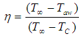 | (1) |
Where, T∞ is the main freestream temperature, Taw is the adiabatic wall temperature and Tc,exit is the coolant temperature from hole. Some literatures related to the present study have been stated. lacovides and Launder [1] found that progress has been made in respect to the flow in serpentine blade cooling passages. Low Re turbulence model was preferred for sub layer region and use of 2nd moment closure in the modelling showed marked improvements in the quality of predictions. Rayleigh number effects can modify heat transfer coefficient in the cooling passages by at least 50%. Kadja and Bergelest [2] and Hasan and Puthukkudi [3] found that effective blade surface cooling can be achieved as blowing ratio is increased but at the expense of reduced cycle efficiency. AL-Hamadi et al. [4] found that increase in free stream turbulence intensity has caused a significant reduction in the local film cooling effectiveness but increase in Stanton number. Effect of freestream turbulence intensity is more apparent on average film cooling effectiveness than on centreline effectiveness due to spreading of jet caused by compound orientation of injectant coolant. Results show that effect of freestream turbulence intensity on film cooling effectiveness and heat transfer characteristics from compound angle holes is similar to that of simple angled holes, whereas compound angle holes give better protection than simple angled holes. Thakur et al. [5] used multi-block pressure correction algorithm, low Re number and wall function k-ε models for 2staggered rows of top & bottom holes. The span wise averaged adiabatic effectiveness showed a better agreement with the experimental data than the spanwise variation. Gritsch et al. [6] presented detailed measurements of local heat transfer coefficient in the vicinity of cooling holes with different hole geometries. Lee et al. [7] found that lateral spreading of injectant around shaped holes at high M result in improvement in adiabatic film cooling effectiveness. Yuen and Botas [8] studied effectiveness of film cooling characteristics of a single round hole at various streamwise angles in a cross flow. Tao et al. [9] found that the std. k-ɛ model gave poorest results whereas k-ω and SST k-ω turbulence model gave relatively better results and produced closer estimation for pressure side and suction side due to isotropic characteristics. Vickery and Iacovides [10] found that maximum effectiveness occurs at some distance downstream of the hole and there is also zero η mid span between a pair of injection holes. Elevated turbulence levels lead to an increase in the coolant and free stream interactions and therefore a reduction in the effectiveness. As M increases which leads to larger recirculation zone employing larger proportion of presence of free stream gas in film cooling. Raj P.Y and K. [11] observed that the SST k-ω turbulence model perform better than standard k-ε model in predicting temperature distribution. Nodal points of attachment present in the flow structure are responsible for an increase in effectiveness near the leading edge of the holes. Kim et al. [12] did comparative analysis on various shapes of film cooling holes. They found that dumbbell-shaped hole shows the best spatially averaged film-cooling effectiveness for all blowing ratios. Elnady et al. [13] did experimental investigation to improve film cooling performance on the leading edge of a gas-turbine vane. They found that cooling effectiveness improved with increase in blowing ratio due to the jet lift-off reduction and hence higher cooling capacity is achieved. Sharma and Garg [14] studied on effects of compound angle and length to diameter ratio on adiabatic film cooling effectiveness. They found that laterally averaged adiabatic effectiveness is the function of length to diameter ratio and compound angle. Jindal et al. [15] studied on film cooling effectiveness and heat transfer on a three dimensional flat plate with a cylindrical, elliptic and triangular holes having an inclination of 30°. It was found that triangular hole shows higher effectiveness than cylindrical hole in the near hole area. It was also observed that triangular hole shows less coolant jet height and high film cooling effectiveness at higher blowing ratios.Thus, conclusions drawn from the above literatures are that the SST k-ω turbulence model gives better result. Film cooling effectiveness depends on various factors such as blowing ratio, hole shape and size, injection angle, temperature, free-stream turbulence, etc which affect turbine blade cooling.
2. Methodology
This study compares film cooling effectiveness over a wide range of blowing ratios (M = 0.33, 0.50, 0.60) with main free-stream velocity at 25m/s, temperature 600K and coolant temperature 300K. Comparison has been made according to different hole geometries which include a standard square shaped hole and a fan-shaped hole and arrangement of hole shapes (square and fan-shaped shower having 7holes in each shower arrangement). The injection angle with respect to lower horizontal plate is 90°. The meshes were created using Gambit. Mesh of square and fan-shaped hole consist of 32,50,000 and 25,65,000 hexahedral cells made using copper scheme respectively. Figure 2.1. shows the computational model of the present study. 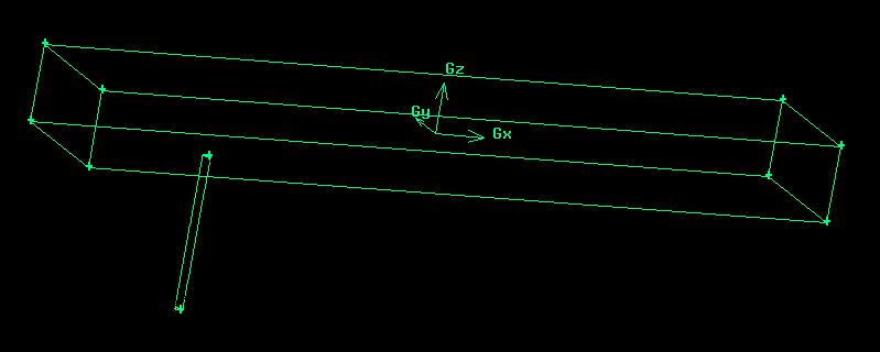 | Figure 2.1. Computational Model |
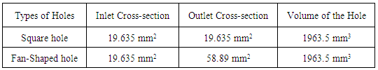
Figure 2.2 shows the meshed geometry of the computational model and Figure 2.3 depicts the schematic side view of the model with its respective dimensions and coolant hole angle equal to 90°. Table 1 gives the information about shape and size of cooling holes used during analysis.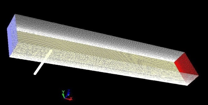 | Figure 2.2. Meshed Geometry |
Table 1. Geometric Shape and Size of Cooling Holes
 |
| |
|
2.1. Boundary Condition
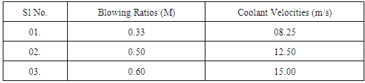
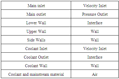
Table 2 shows the corresponding coolant velocity used according to different blowing ratios. Boundary condition which has been set in the model is shown in Table 3. A velocity-inlet boundary condition has been set at main inlet with x-velocity equal to 25 m/s. The mainstream and coolant temperatures are 600K and 300K respectively. The coolant injection angle is 90° as shown in Figure 2.3.Table 2. Blowing Ratios and Coolant Inlet Velocities
 |
| |
|
Table 3. Boundary Condition
 |
| |
|
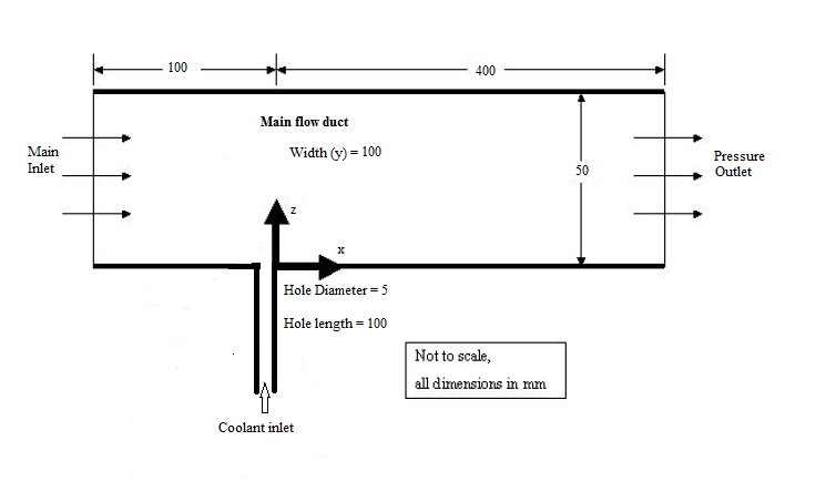 | Figure 2.3. Model with Dimensions |
3. Validation and Grid Independency Test
The computational model has been validated with benchmark experimental literature of Yuen and Botas [8] who studied experimentally on a cylindrical hole with a stream wise angle of 30°, 60° and 90° for a circular hole case at M = 0.33 as shown in Figure 3.1. The grid dependency test has also been carried out and shown in Figure 3.2. Following the grid density study, it was concluded that the coarse grid gave the best comparison to published experimental results and thus has been used for subsequent computations. The SST k-ω turbulence model has been used to determine film cooling effectiveness with low Re correction and viscous heating as the study is mainly concerned at cooling the blade walls. The SST formulation also switches to a k-ε behaviour in the free-stream and thereby avoids the common k-ω problem that the model is too sensitive to the inlet free-stream turbulence properties. The SST k-ω model show good behaviour in adverse pressure gradients and separating flow. This model produces large turbulence levels in regions with large normal strain, like stagnation regions and regions with strong acceleration. The present study focuses on near wall conditions and SST k-ω turbulence model is most appropriate for the given condition. From the study of Tao et al. [9] and Raj P.Y and K. [11] it has been found out that SST k-ω turbulence model provides better results compared to other turbulence models. The computational model with the SST k-ω turbulence model has also been validated with a reputed experimental literature [8].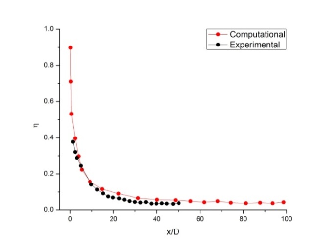 | Figure 3.1. Centerline Effectiveness for Single Circular Hole at Blowing Ratio (M) = 0.33 [8] |
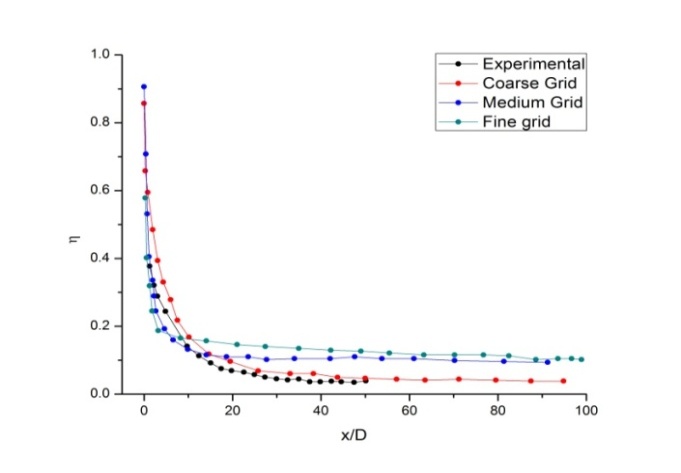 | Figure 3.2. Grid Independency Test [8] |
4. Results and Discussions
Comparison of centreline and spatially averaged effectiveness for single square and fan-shaped hole at an axial distance of 400 mm from the leading edge of the blade and square and fan-shaped shower for M = 0.33 respectively are shown in Figures 4.1 and 4.2. The inlet surface area of each shape that is square and fan-shaped have been kept constant so as to have equal mass flow rate through each shape. In case of fan-shaped the exit area is thrice the entry area which has been found out from the work of Gritsch et al. [6] since fan-shaped are categorized as expanded exits.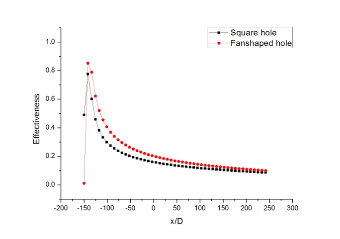 | Figure 4.1. Centerline Effectiveness for Single Hole at M=0.33 |
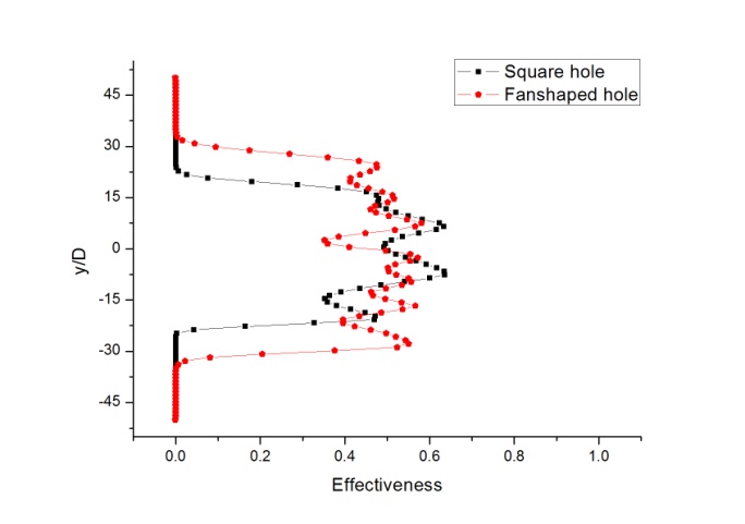
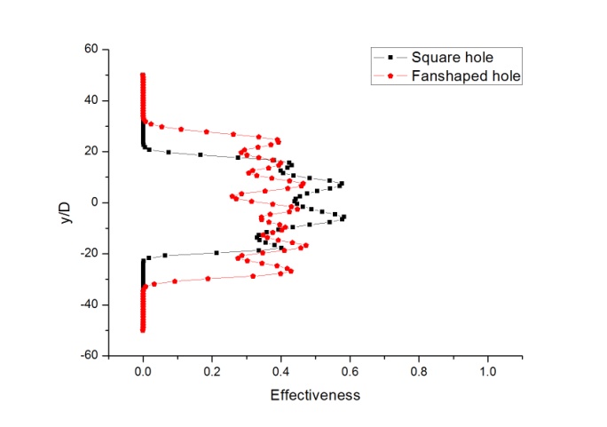 | Figure 4.2. Spatially Averaged Effectiveness for Single Shower at M=0.33 |
Figures 4.3 and 4.4 show comparison of centreline and spatially averaged effectiveness for single square and fan-shaped hole at an axial distance of 400 mm from the leading edge of the blade and square and fan-shaped shower for M = 0.50 respectively. Effectiveness at coolant exit for square hole case is less due to presence of lateral separation of kidney vortices.Hence, for square hole centreline effectiveness is less than fan-shaped hole. In fan-shaped hole, film cooling effectiveness is minimum at hole exit due to coolant jet lift off. Then, in the downstream of cooling hole coolant jet reattachment takes place and effectiveness almost approaches to unity.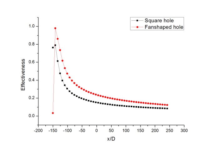 | Figure 4.3. Centerline Effectiveness for Single Hole at M=0.50 |
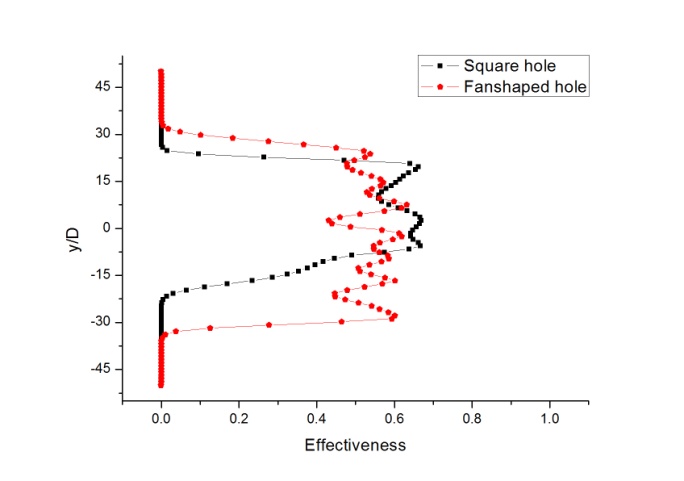
 | Figure 4.4. Spatially Averaged Effectiveness for Single Shower at M=0.50 |
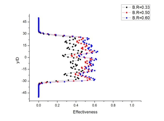
Comparison of centreline and spatially averaged effectiveness for single square and fan-shaped hole and square and fan-shaped shower for M = 0.60 are shown in Figures 4.5 and 4.6 respectively. Results show that fan-shaped hole is giving highest spatially averaged effectiveness as well as centreline effectiveness. It is due to expanded exits as area gradually increases at exit and hence velocity decreases. Thus coolant gets enough time to stay on the plate near the hole which results in increase in effectiveness longitudinally as well as laterally. Hence, keeping mass flow rate of coolant constant and number of cooling holes constant larger surface area of plate can be cooled with the help of fan-shaped shower arrangement.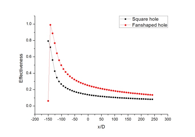 | Figure 4.5. Centerline Effectiveness for Single Hole at M=0.60 |
 | Figure 4.6. Spatially averaged Effectiveness for Single Shower at M=0.60 |
Comparison of centreline and spatially averaged effectiveness for single square and fan-shaped hole at an axial distance of 400 mm from the leading edge of the blade and square and fan-shaped shower for M = 0.60 are shown in Figures 4.7 and 4.8 respectively. As blowing ratio increase, coolant spread over a longer distance downstream of the cooling holes as well as laterally, thus increasing effectiveness. Thus, M = 0.60 is giving maximum centreline as well as spatially averaged effectiveness compared to other blowing ratios.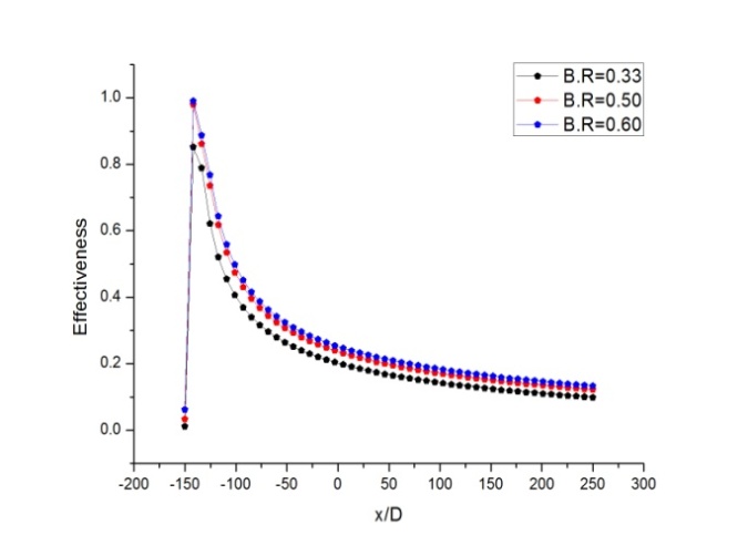 | Figure 4.7. Centerline Effectiveness for a Fan-shaped Hole at Different M |
 | Figure 4.8. Spatially Averaged Effectiveness for Fan-shaped Shower at Different Blowing Ratio |
Figure 4.9 shows the comparison of spatially averaged effectiveness of single fan-shaped hole and fan-shaped shower having 7holes for M = 0.60. It is clear from the result that by increasing the number of cooling holes larger surface area of blade can be cooled keeping mass flow rate of coolant constant.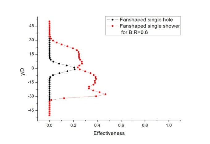 | Figure 4.9. Spatially Averaged Effectiveness η for Fan-shaped Single Hole and Shower at M = 0.60 |
Temperature contour of fan-shaped shower is shown in Figure 4.10. Temperature of the plate near the hole almost reaches 300K as coolant comes out from an expanded exit. Since exit area is more, velocity of coolant decreases and coolant gets more time to reside on the plate near the hole. Thus, cooling from fan-shaped hole is more effective than square shaped hole.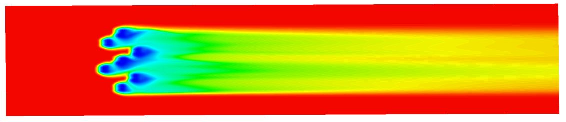 | Figure 4.10. Temperature Contour for Fan-Shaped Shower at M = 0.60 |
Figure 4.11 shows velocity contour of fan-shaped hole. It shows that recirculation zone is formed near the hole and it spreads laterally. Recirculation of coolant does not disturb the coolant flow path further downstream from cooling hole.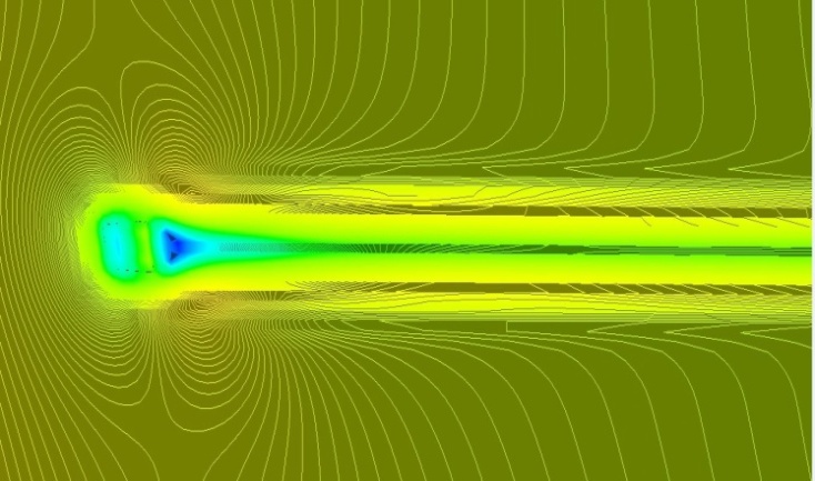 | Figure 4.11. Velocity contour for fan-Shaped Shower at M = 0.60 |
5. Conclusions
On comparing centerline effectiveness for single hole, it is observed that effectiveness is very less at the coolant exit for single square hole and fan-shaped hole due to coolant jet lift off but after that effectiveness increase rapidly because of coolant jet reattachment. Effectiveness decrease with increase in blowing ratios for square hole shape because large proportion of coolant mix with mainstream flow rapidly. Spatially averaged effectiveness for fan-shaped is higher than square because of better lateral spreading of coolant due to expanded exit as velocity of coolant decrease at exit giving enough time to coolant to stay on plate near the hole and thus cool the area. Additionally, effectiveness increase with increase in blowing ratio as coolant spread more laterally as well as longitudinally. While for lower blowing ratio, coolant is unable to spread over a longer distance downstream of cooling holes. Thus, best results were obtained for fan-shaped hole with M = 0.60 and keeping mass flow rate of coolant constant for all the cases. Effectiveness of square is less in longitudinal direction because of the presence of lateral separation of kidney vortices just downstream of the coolant hole exit. Thus, coolant from square hole spread more laterally than longitudinally. Effectiveness is zero at the mid span between two pair of injection holes and where there are no cooling holes. Thus according to shapes, fan-shaped hole gave the best result compared to square hole shape.
ACKNOWLEDGEMENTS
I take this auspicious opportunity to express my deep sense of gratitude to my guide Dr. A.K Roy, Associate Professor and co-guide Mr. Prakhar Jindal, PhD. Scholar, Dept. of Mechanical Engineering, B.I.T. Mesra, Ranchi, for their pioneer guidance and innovative ideas in scrutinizing my work at every stage and this work would not see the light of completion without their continuous encouragement.I convey my deep sense of gratitude to Dr. Arbind Kumar, Head, Dept. of Mechanical Engineering, B.I.T, Mesra, Ranchi, for providing me with the requisite facilities and facilities extended by him while carrying out this work.
References
| [1] | H. lacovides and B. E. Launder, “Computational fluid dynamics applied to internal gas-turbine blade cooling: a review,” International Journal Heat and Fluid Flow, 16: 454-470, 1995. |
| [2] | Mahfoud Kadja and George Bergelest, “Computational study of turbine blade cooling by slot-injection of gas,” Applied Thermal Engineering, Vol. 17, No. 12. pp. 1141-1149, 1997. |
| [3] | Reaz Hasan, Agin Puthukkudi, “Numerical study of effusion cooling on an adiabatic flat plate,” Propulsion and Power Research 2013:2(4):269-275. |
| [4] | A.K. Al-Hamadi, B. A. Jubran and G. Theodoridis, “Turbulence intensity effects on film cooling and heat transfer from compound angle hole with particular application to gas turbine blades,” Energy Conversion Management, Vol. 39, No. 14, pp. 1449-1457, 1998. |
| [5] | Siddharth Thakur, Jeffrey Wright, Wei Shyy, “Convective film cooling over a representative turbine blade leading edge,” International Journal of Heat and Mass Transfer, 42 2269-2285, 1999. |
| [6] | Michael Gritsch, Achmed Schulz, Sigmar Wittig, “Film cooling holes with expanded exits – Near hole heat transfer coefficients,” International Journal Heat and Fluid Flow. 22 134-142, 2001. |
| [7] | Hong-Wook Lee, Jung Joon Park, JoonSik Lee, “Flow visualization and film cooling effectiveness measurements around shaped holes with compound angle orientations,” International Journal Heat and Mass Transfer. 45 145-156, 2002. |
| [8] | C.H.N. Yuen and R.F. Martinez-Botas, “Film Cooling Characteristics of a Single Round Hole at Various Streamwise Angles in a Crossflow: Part I Effectiveness,” International Journal of Heat and Mass Transfer. 46 221-235, 2003. |
| [9] | Zhi Tao, Zhenming Zhao, Shuiting Ding, GuoqiangXu, Hongwei Wu, “Suitability of three different two-equation turbulence models in predicting film cooling performance over a rotating blade,” International Journal Heat and Mass Transfer. 52 1268-1275, 2008. |
| [10] | W Vickery and H Iacovides, “Computation of gas turbine blade film cooling,” Turbulence Mechanics Group, 11th UK National Heat Transfer Conference, 2009. |
| [11] | Deepak Raj P.Y, Devaraj. K, “Numerical Heat Transfer Analysis of a Flat Plate using Combined Jet Impingement and Film cooling, with Flow Patterns,” International Journal of Engineering Research and Technology. ISSN: 2278-0181, Vol. 2 Issue 11, November-2013. |
| [12] | Sun-Min Kim, Ki-Don Lee and Kwang-Yong Kim, “A comparative analysis of various shaped film-cooling holes,” Heat Mass Transfer Springer-Verlag, DOI 10.1007/s00231-012-1043-5, 2012. |
| [13] | Tarek Elnady, Ibrahim Hassan, Lyse Kadem, Terry Lucas, “Cooling effectiveness of shaped film holes for leading edge,” Experimental Thermal and Fluid Science 44 649–661, 2013. |
| [14] | Vidit Sharma, Ashish Garg, “Numerical investigation of effects of compound angle and length to diameter ratio on adiabatic film cooling effectiveness,” ASME, arXiv: 1405.0560v1 [cs.CE] 3 May, 2014. |
| [15] | Prakhar Jindal, A.K. Roy, R.P. Sharma, “Numerical Study of film cooling for various coolant inlet geometries,” International Journal of Engineering and Technology, ISSN : 0975-4024 Vol 7 No 5 Oct-Nov 2015. |

 Abstract
 Reference
 Full-Text PDF
 Full-text HTML