-
Paper Information
- Paper Submission
-
Journal Information
- About This Journal
- Editorial Board
- Current Issue
- Archive
- Author Guidelines
- Contact Us
American Journal of Fluid Dynamics
p-ISSN: 2168-4707 e-ISSN: 2168-4715
2016; 6(1): 1-10
doi:10.5923/j.ajfd.20160601.01

Numerical Simulation of Two-Dimensional Laminar Flow and Heat Transfer through a Rotating Curved Square Channel
 Abstract
 Reference
 Full-Text PDF
 Full-text HTML
Md. Nurul Amin Helal 1, Bishnu Pada Ghosh 2, Rabindra Nath Mondal 2
1Additional Director (Education), Training Directorate, BGB Head Quarter, Pilkhana, Dhaka, Bangladesh
2Department of Mathematics, Jagannath University, Dhaka, Bangladesh
Correspondence to: Rabindra Nath Mondal , Department of Mathematics, Jagannath University, Dhaka, Bangladesh.
| Email: |  |
Copyright © 2016 Scientific & Academic Publishing. All Rights Reserved.
This work is licensed under the Creative Commons Attribution International License (CC BY).
http://creativecommons.org/licenses/by/4.0/

Numerical simulation on fully developed two-dimensional laminar flow of viscous incompressible fluid through a rotating curved square channel with curvature 0.2 has been performed by using a spectral method and applying a temperature difference across the vertical sidewalls. The outer wall of the channel is heated while the inner wall cooled, the top and bottom walls being adiabatic. Water is used as a working fluid of the study. A rotation of the channel about the center of curvature is imposed in the positive direction, and combined effects of centrifugal, Coriolis and buoyancy forces are investigated in detail. As a result, three branches of asymmetric steady solutions with two-, three- and four-vortex solutions are obtained by the Newton-Raphson iteration method. Then, in order to study the non-linear behavior of the unsteady solutions, time evolution calculations as well as their phase spaces are obtained, and it is found that time periodic flow turns into chaos/transitional chaos through multi-periodic oscillations, if Tr is increased. Streamlines of secondary flows and isotherms of temperature profiles are obtained, and it is found that the unsteady flow consists of asymmetric two- to four-vortex solutions. Convective heat transfer is also investigated, and it is found that chaotic flow enhances heat transfer more effectively than the periodic or multi-periodic solutions due to strong secondary vortices. External heating is shown to generate a significant temperature gradient at the outer concave wall of the channel.
Keywords: Rotating curved duct, Secondary flow, Steady solutions, Time evolution, Dean number, Taylor number
Cite this paper: Md. Nurul Amin Helal , Bishnu Pada Ghosh , Rabindra Nath Mondal , Numerical Simulation of Two-Dimensional Laminar Flow and Heat Transfer through a Rotating Curved Square Channel, American Journal of Fluid Dynamics, Vol. 6 No. 1, 2016, pp. 1-10. doi: 10.5923/j.ajfd.20160601.01.
Article Outline
1. Introduction
- The study of flows and heat transfer through curved ducts and channels is of fundamental interest because of its practical applications in chemical, mechanical, civil and biological engineering. Due to engineering applications and their intricacy, flow in a rotating curved channel has become one of the most challenging research fields of fluid mechanics. A quantitative analogy between flows in stationary curved pipes and orthogonally rotating straight pipes has been reported by Ishigaki [1, 2]. Taking this analogy as a basis, this study describes the characteristics of more general and complicated flow in rotating curved channels, which are relevant to systems involving helically or spirally coiled pipes rotating about the coil axis. Such rotating flow passages are used in cooling systems in rotating machinery such as in gas turbines, electric generators and electric motors. The readers are referred to Berger et al. [3] and Nandakumar and Masliyah [4] for some outstanding reviews on rotating and stationary curved duct flows.The forced convection in a curved channel of square cross-section is characterized by three dimensionless governing parameters: one is geometrical parameter δ (curvature), another one thermos-physical parameter Pr (the Prandtl number) and the other one dynamical parameter Dn, the Dean number. The fully developed bifurcation structure of the forced convection in loosely coiled ducts has been well studied in low Dean number region (Winters [5]). The readers are referred to Yang and Wang [6] and Mondal et al. [7] for the effects of rotation-induced Coriolis force and buoyancy force on flow multiplicity in loosely coiled ducts. The location of limit and bifurcation points was found to be insensitive for curvature ratios less than 0.1, but at higher curvature ratios, they move to higher Dean numbers (Mondal et al. [8]). Upon increasing the Dean number, a richer bifurcation structure with new limit/bifurcation points, solution branches and complicated flow structures is obtained (Wang and Liu [9]) due to the stronger non-linearity of the problem. Because of the lack of solution structures in high Dean number region, there is a long-standing controversy over solutions obtained by different methods without considering the multiplicity. The present work is, therefore, a relatively comprehensive study on the bifurcation structure for the laminar forced convection in a rotating curved square channel at a high Dean number region, because it has practical applications in metallic industry, gas turbines, electric generators/motors etc.The flow through a rotating curved duct is another subject which has attracted considerable attention because of its importance in engineering devices. Early works on rotating curved duct flows were constrained to two simplified limiting cases with strong or weak rotations. Miyazaki [10] studied the characteristics of the flow and heat transfer in the rotating curved rectangular duct with positive rotation. Employing finite volume method, Wang and Cheng [11] examined the flow characteristics and heat transfer in curved ducts for positive cases and found reverse secondary flows for the co-rotation cases. Selmi and Nandakumar [12] and Yamamoto et al. [13] performed extensive works on the rotating curved duct flows and their bifurcations. Ligrani and Niver [14] identified several of other oscillating modes as well as unsteady splitting and merging of Dean vortices. Yang and Wang [6] performed comprehensive numerical study on bifurcation structure and stability of solutions for laminar mixed convection in a rotating curved duct of square cross section. However, transient behavior of the unsteady solutions, such as periodic, multi-periodic or chaotic solutions are not yet resolved for the non-isothermal flows in a rotating curved square channel with differentially heated vertical sidewalls in the presence of strong rotational speed with large pressure gradients, which is one of the goals of the present study.It is well known that, the fluid flowing in a rotating curved duct is subjected to two forces: the Coriolis force, caused by the rotation of the duct, and the centrifugal force caused by the curvature of the duct. For isothermal flows of a constant property fluid, the Coriolis force tends to produce vortices while centrifugal force is purely hydrostatic. When a temperature induced variation of fluid density occurs for non-isothermal flows, both Coriolis and centrifugal type buoyancy forces can contribute to the generation of vortices (Wang and Cheng [11]). These two effects of rotation either enhance or counteract each other in a non-linear manner depending on the direction of wall heat flux and the flow domain. Therefore, the effect of system rotation is more subtle and complicated and yields new; richer features of flow and heat transfer in general, bifurcation and stability in particular, for non-isothermal flows (Mondal et al. [15]). Recently, Mondal et al. [16] performed solution structure, stability and pattern variation of secondary vortices for Dean-Taylor flow through a rotating curved rectangular duct. They obtained dual and multi-vortex solutions at the same value of the Taylor number. Very recently, Razavi et al. [17] numerically studied flow characteristics, heat transfer and entropy generation in a rotating curved duct by using control volume method. The effects of Dean number, non-dimensional wall heat flux, and force ratio on the entropy generation due to friction and heat transfer irreversibility and overall entropy generation were also presented in that paper. However, transitional behavior of the unsteady solutions with combined effects of centrifugal-Coriolis instability is still absent in literature, which has been described in the present paper. Furthermore, hydrodynamic instability, vortex generation and role of secondary flows on convective heat transfer via periodic, multi-periodic or chaotic flows, which has been presented in the present study, is a clear concept to observe the vortex-structure phenomena. Furthermore, the present study shows that there is a strong interaction between the heating-induced buoyancy force and the centrifugal-Coriolis instability in the rotating curved channel, which stimulates fluid mixing and thus results in thermal enhancement in the flow by the secondary vortices. This process is accurately demonstrated by the temperature contours as shown in the present study. Studying the effects of rotation on the unsteady flow characteristics is another objective of the present study.
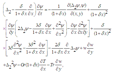
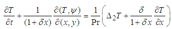
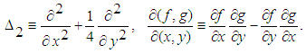
2. Governing Equations
- Consider fully developed two-dimensional (2D) flow of viscous and incompressible fluid through a rotating curved square duct. The coordinate system is shown in Figure 1, where the
 and
and  axes are taken to be in the horizontal and vertical directions respectively, and
  is the coordinate along the center-line of the duct, i.e., the axial direction. The system rotates at a constant angular velocity
  around the
  axis. It is assumed that the outer wall of the duct is heated while the inner wall cooled. It is also assumed that the flow is uniform in the axial direction, which is driven by a constant pressure gradient G along the centre-line of the duct. The dimensional variables are non-dimensionalized by using the representative length d and the representative velocity
  where
where  is the kinematic viscosity of the fluid. We introduce the non-dimensional variables defined as:
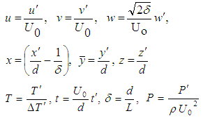 where
where 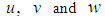 are the non-dimensional velocity components in the
  directions, respectively;
  is the non-dimensional time, P is the non-dimensional pressure,
  is the non-dimensional curvature defined as
  and temperature is non-dimensionalized by
 | Figure 1. Physical model and the coordinate system |
 is introduced in the x- and y-directions as
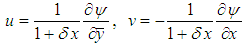 | (1) |
 , the stream function
  and temperature T are expressed in terms of non-dimensional variables as
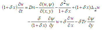 | (2) |
 | (3) |
 | (4) |
 The non-dimensional parameters Dn, the Dean number; Gr, the Grashof number; Tr, the Taylor number and Pr, the Prandtl number, which appear in equations (2) to (4) are defined as
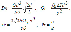 | (5) |
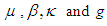 are the viscosity, the coefficient of thermal expansion, the co-efficient of thermal diffusivity and the gravitational acceleration respectively. The rigid boundary conditions for
  and
and  are used as
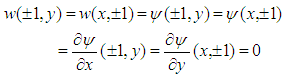 | (6) |
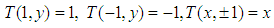 | (7) |
 | (8) |
 and Pr are fixed as Dn = 2000, Gr = 1000,
  and Pr = 7.0 (water).
 3. Numerical Calculations
3.1. Method of Numerical Calculation
- In order to solve the Eqs. (2) to (4) numerically, spectral method is used. Details of this method is discussed in Mondal [18]. The main objective of this method is to use the expansion of the polynomial functions, that is, the variables are expanded in the series of functions consisting of Chebyshev polynomials. The expansion functions
 and
and  are expressed as
 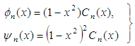 | (9) |
 is the n-th order Chebyshev polynomial.
  and
and  are expanded in terms of
  and
and  as:
as: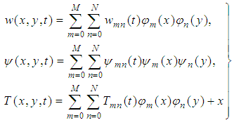 | (10) |
 and
and  are obtained. The collocation points
  are taken to be
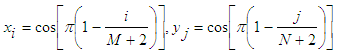 | (11) |
 and
and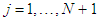 . The steady solutions are obtained by the Newton-Rapshon iteration method. The convergence is assured by taking
  defined as:
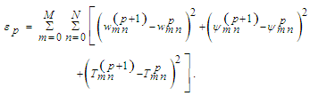 | (12) |
3.2. Time-Evolution Calculation
- In order to calculate the unsteady solutions, the Crank-Nicolson and Adams-Bashforth methods together with the function expansion (10) and the collocation method is used. Details of this method is discussed in Mondal [18]. By applying the Crank-Nicolson and the Adams-Bashforth methods to the basic equations (2)-(4), and rearranging, we obtain,
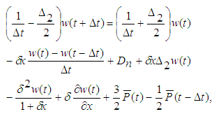 | (13) |
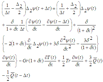 | (14) |
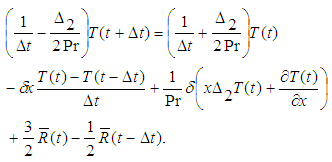 | (15) |
 and
and  are the non-linear terms. Then applying the Adams-Bashforth method for the second term of R.H.S of Eqs. (13) to (15) and simplifying we calculate
 ,
,  and
and  by numerical computation.
3.3. Numerical Accuracy
- The accuracy of the numerical calculations is investigated for the truncation numbers M and N used in this study. For good accuracy of the solutions, N is chosen equal to M. Five types of grid generations were used to check the dependence of the solutions as shown in Table 1. In Table 1, the values of Q and
 obtained for Dn = 2000, Gr = 1000 and Tr = 1000 at
  are shown, where Q is the flux through the duct and
  is the axial velocity of the steady solutions at
|


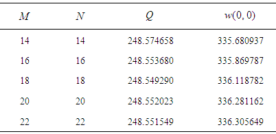
 to
to  be 0.0084%;
  to
to  is 0.0017%;
  to
to  be 0.0011% and
  to
to  be 0.0001%. Also the change of the axial velocityis 0.0562% from
  to
to  ; 0.0741% from
  to
to  ; 0.048% from
  to
to  and 0.0072% from
  to
to  . Therefore, it is evident that
 gives sufficient accuracy of the present numerical solutions.
4. Flux through the Duct
- The dimensional total flux
 through the duct in the rotating coordinate system is calculated by:
  | (16) |
 | (17) |
 is expressed as
  In the present study,
  is used to denote the steady solution branches and to perform time-evolution of the unsteady solutions.
5. Results and Discussion
5.1. Solution Structure of the Steady Solutions
- After a comprehensive survey over the parametric ranges, three branches of asymmetric steady solutions with two- to four-vortex solutions are obtained for Dn = 2000 and Gr = 1000 over a wide range of
 for curvature
  The solution structure of the steady solutions is shown in Fig. 2, where the first steady solution branch (first branch) is shown by thin solid line, the second steady solution branch (second branch) by thick solid line and the third steady solution branch (third branch) by dashed line. The steady solution branches are obtained by using path continuation technique as discussed in Keller [20]. It is found that there is no bifurcating relationship among the branches. The first branch exists throughout the whole range of Tr investigated in this study. The second branch consists of two parts, the lower part and the upper part. The lower part contains two-vortex solution while the upper part four-vortex solution. The branch starts at small Tr (Tr = 0) and extends in the direction of increasing Tr (decreasing Q) up to Tr = 1425, and then the branch turns to the opposite direction with increasing Q (decreasing Tr) and finally stop at Tr = 0. The third branch has nearly the same characteristics as of the second branch, which starts at Tr = 0 and extends up to Tr = 2000 and then it turns to the opposite direction and finally end at Tr = 0.
 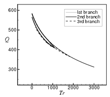 | Figure 2. Solution structure of steady solutions for Dn = 2000, Gr = 1000 at  |
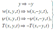
 = constant) and temperature profiles (isotherms, T = constant) are drawn on various branches of steady solutions as shown in Fig. 3. To draw the contours of
  and T, the increments
  = 0.6 and ∆T = 0.2 are used. The same increments of
  and T are used for all the figures in this paper, unless specified. The right-hand side of each duct box of
  and T indicates outside direction of the duct curvature. In the figures of the streamlines, solid lines
  show that the secondary flow is in the counter clockwise direction while dotted lines
  in the clockwise direction. Similarly, in the figures of isotherms, solid lines are those for
  and dotted ones for T < 0. As seen in Fig. 3, the secondary flow is an asymmetric two-vortex solution on the first branch, while asymmetric two- to four-vortex on the second and third branches. It is readily noted that the patterns of secondary flows are fundamentally different from those in a straight channel; even at low flow rate (low Dean number), the flow profile has two large counter-rotating vortices. This vortex flow is developed consequent to the combined action of the centrifugal, Coriolis and buoyancy forces induced by the duct stream-wise curvature.
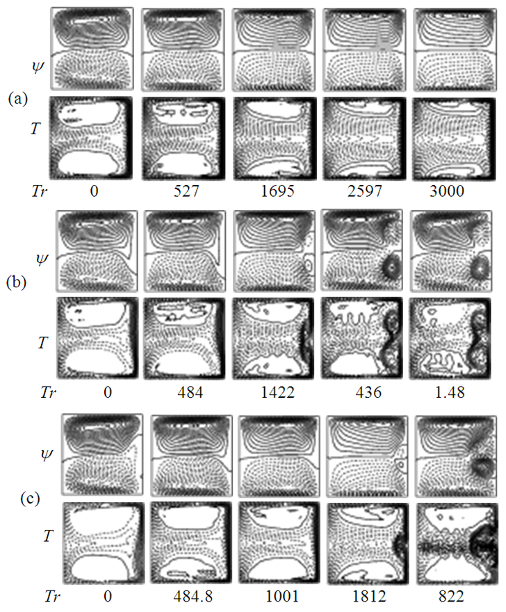 | Figure 3. Contours of secondary flow patterns (top) and temperature profiles (bottom) on the steady solution branches at several values of Tr. (a) On the first branch, (b) On the second branch and (c) On the third branch |
5.2. Unsteady Solutions
- In order to study the non-linear behavior of the unsteady solutions, time-evolution calculations are performed for
 atand Gr = 1000. Time evolution of Q for
  showed that the unsteady flow is a steady-state solution. Then, in order to observe unsteady flow characteristics for
 time evolution calculations are performed at Tr = 200, 500, 700 and 900. Time evolution of Q for Tr = 200 is shown in Fig. 4(a), where it is seen that the flow oscillates periodically. With a view to observe the change of the flow characteristics as time proceeds, typical contours of secondary flow patterns and temperature distributions are shown in Fig. 4(b) for one period of oscillation at
 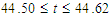 , and it is found that the periodic flow at Tr = 200 oscillates between asymmetric two-vortex solutions.
 | Figure 4. Unsteady solution for Tr = 200, Dn = 2000 and Gr = 1000. (a) Time evolution of Q. (b) Contours of secondary flow patterns (top) and temperature profiles (bottom) for one period of oscillation at  |
 , and it is found that the unsteady flow at Tr = 700 oscillates between asymmetric two-vortex solution. Similarly, time evolution of Q for Tr = 900 is studied as presented in Fig. 7(a). Figure Fig. 7(a) shows that the unsteady flow at Tr = 900 oscillates multi-periodically. Typical contours of secondary flow patterns and temperature profiles are then shown in Fig. 7(b) for
  where it is seen that the unsteady flow at Tr = 900 also oscillates between the asymmetric two-vortex solutions. In fact, the periodic oscillation, which is observed in the present study, is a traveling wave solution advancing in the downstream direction which is well justified in the recent investigation by Yanase et al. [21] for a three-dimensional (3D) travelling wave solutions as an appearance of 2D periodic oscillation.
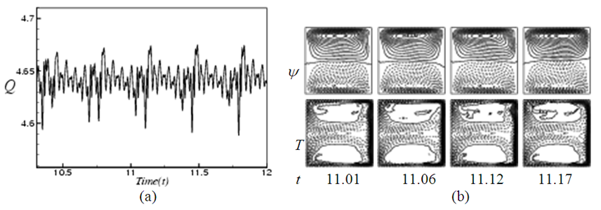 | Figure 5. Unsteady solution for Tr = 500, Dn = 2000 and Gr = 1000. (a) Time evolution of Q. (b) Contours of secondary flow patterns (top) and temperature profiles (bottom) at  |
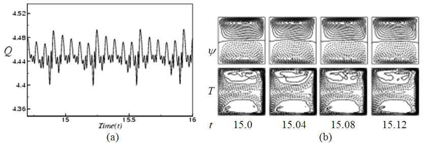 | Figure 6. Unsteady solution for Tr = 700, Dn = 2000 and Gr = 1000. (a) Time evolution of Q. (b) Contours of secondary flow patterns (top) and temperature profiles (bottom) at 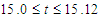 |
5.3. Phase Spaces
- In this section, in order to discuss the transitional behavior of the unsteady solutions i.e. whether the unsteady flow is periodic, multi-periodic or chaotic, the orbits of the phase spaces of the time evolution results are obtained. The change of the flow state from periodic oscillation to transitional chaos and then multi-periodic or periodic is explicitly exhibited by drawing the orbits of the phase spaces in the
 plane, where
  as shown in Figs. 8(a) to 8(d) for Tr = 200, 500, 700 and 900 respectively. The orbits are drawn by tracing the time evolution of the solutions. As seen in Fig. 8(a), the time evolution result presented in Fig. 4 for Tr = 200 is periodic. But as seen in Fig. 8(b), which shows the phase orbits of the time evolution result for Tr = 500 (Fig. 5) shows that the flow is chaotic, though it was not clear in the time evolution result. This type of flow evolution is termed as transitional chaos (Mondal et al. [8]). Similarly, phase space (Fig. 8(c)) of the time evolution result for Tr = 700 (Fig. 6) shows that it is also chaotic. However, Fig. 8(d) shows that the flow is a transitional chaos for Tr = 900 at some extent rather than multi-periodic as predicted in Fig. 7.
 | Figure 7. Unsteady solution for Tr = 900, Dn = 2000 and Gr = 1000. (a) Time evolution of Q. (b) Contours of secondary flow patterns (top) and temperature profiles (bottom) at  |
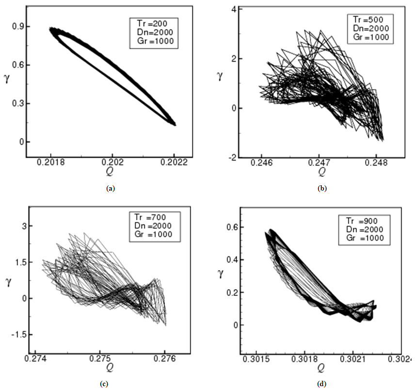 | Figure 8. Phase plots in the  plane for Dn = 2000 and Gr = 1000 at plane for Dn = 2000 and Gr = 1000 at  (a) Tr = 200, (b) Tr = 500, (c) Tr = 700, (d) Tr = 900 (a) Tr = 200, (b) Tr = 500, (c) Tr = 700, (d) Tr = 900 |
6. Conclusions
- A comprehensive numerical study on fully developed two-dimensional flow of viscous incompressible fluid through a rotating curved square channel has been performed by using a spectral method, and covering a wide range of the Taylor number
 . In the present study, flow characteristics are investigated for Dn = 2000 and Gr = 1000 for a constant curvature of the channel at
  . After a comprehensive survey over the parametric ranges, three branches of asymmetric steady solutions are obtained by using path continuation technique. It is found that there exist asymmetric two-, three- and four- vortex solutions on the steady solution branches. These vortices are generated due to combined action of the centrifugal, Coriolis and buoyancy forces. It is found that the first steady solution branch exists throughout the whole range of Tr, which consists of asymmetric two-vortex solutions. The second branch is composed of asymmetric two- and four-vortex solutions while the third branch asymmetric two- and four-vortex solutions but different from those of the second steady solution branch. Then in order to study non-linear behavior of the unsteady solutions, time-evolution calculations were performed, and it is found that the unsteady flow becomes periodic first, then chaotic (transitional chaos) and finally turns into multi-periodic if Tr is increased. Drawing the phase spaces was found to be very fruitful to well identify the transition of the unsteady flow characteristics. In the case of heat transfer from the heated wall to the fluid, it is found that convective heat transfer is significantly enhanced as the rotation increases. It is also found that there is a strong interaction between the heating-induced buoyancy force and the centrifugal-Coriolis instability of the flow in the curved channel that stimulates fluid mixing and consequently enhance heat transfer in the fluid. It should be noted here that irregular oscillation of the flow through a curved duct has been observed experimentally by Ligrani and Niver [14] for the large aspect ratio and by Wang and Yang [22] for the curved square duct.