Abdul Rahiman , Abdul Razak R. K. , Mohammad Samee A. D. , Ramis M. K.
Department of Mechanical Engineering, P.A. College of Engineering, Mangalore, India
Correspondence to: Ramis M. K. , Department of Mechanical Engineering, P.A. College of Engineering, Mangalore, India.
| Email: |  |
Copyright © 2014 Scientific & Academic Publishing. All Rights Reserved.
Abstract
Air motion inside the intake manifold is one of the important factors, which govern the engine performance and emission of multi-cylinder diesel engines. Hence the flow phenomenon inside the intake manifold should be fully understood in order to consider the current requirement of higher engine efficiency and lower emission. In this project work, the internal flow characteristic in the intake manifold of a diesel engine is investigated computationally for the different intake manifold (Helical, Spiral and Helical-Spiral) configurations. The governing equations for unsteady, three-dimensional, compressible, turbulent flow are solved with the two equation RNG k-ε model to consider the complexity of the geometry and fluid motion. The overall flow field inside the intake manifold and various quantities, such as swirl and tumble ratios were examined for all three types of manifolds. It was concluded that spiral and helical-spiral manifold creates higher swirl than normal inlet manifold. However, volumetric efficiency was observed to be higher for helical manifold.
Keywords:
Spiral manifolds, Helical manifolds, Spiral-Helical combined manifolds, Swirl, Turbulence, CFD and diesel engine
Cite this paper: Abdul Rahiman , Abdul Razak R. K. , Mohammad Samee A. D. , Ramis M. K. , CFD Analysis of Flow Field Development in a Direct Injection Diesel Engine with Different Manifolds, American Journal of Fluid Dynamics, Vol. 4 No. 3, 2014, pp. 102-113. doi: 10.5923/j.ajfd.20140403.03.
1. Introduction
In today’s world, major objectives of engine designers are to achieve the twin goals of best performance and lowest possible emission levels. To maximize the mass of air inducted into the cylinder during the suction stroke, the intake manifold design, which plays an important role, has to be optimized. The design becomes more complex in case of a multicylinder engine as air has to be distributed equally in all the cylinders. Hence, configuration of manifold geometry becomes an important criterion for the engine design. Achieving this by means of experimental methods would cost time and money. There is a need for computational fluid dynamics (CFD) method (numerical method), which could estimate the volumetric efficiency of the engine during the design stage itself, without undergoing any time consuming experiments. Also mapping the total pressure distribution at the manifold, port and valve is an effective method for analyzing computational prediction of the flow separation process in the region upstream of the valve stem and in the vicinity of the valve seat, because the total pressure is influenced by the mean. Many researchers have studied on Intake manifold distribution of diesel engine aspects that constitute a premise to the modeling and simulation of intake manifold with Exhaust Gas Recirculation (EGR) and intake port alone at different valve lift in the past. Robert et al, [1] investigated two important, common fluid flow patterns from CFD simulations Fluent, namely, swirl and tumble motion typical of automotive engines and visualize swirl and tumble flow using three different flow visualization techniques: direct, geometric, and texture-based. When illustrating these methods side-by-side, they describe the relative strengths and weaknesses of each approach. Chen et al, [2] combined experimental and computational study of the steady flow through an internal combustion engine inlet port. The port was of generic design with a straight centerline. The three-dimensional velocity and turbulence fields in the port and cylinder were simulated. Comparisons of the numerical predictions with the experimental data indicated that the mean flow features are accurately predicted in many parts of the flow field. Benny and Ganesan [3] studied on the effect of helical, spiral, and helical-spiral combination manifold configuration on air motion and turbulence inside the cylinder of a Direct Injection (DI) diesel engine motored at 3000 rpm. The flow characteristics of these engine manifolds are examined under transient conditions using Computational Fluid Dynamics code STAR CD. The predicted CFD results of mean swirl velocity of the engine at different locations inside the combustion chamber at the end of compression stroke were compared with experimental results available in the literature. They also compared the volumetric efficiency of the modeled helical manifold. The results obtained showed reasonably good agreement with the measured data given in the literature. Kurniawan et al, [4] investigated the effect of the piston crown inside the combustion chamber of a 4-stroke direct injection automotive engine under the motoring condition. The analyses are dedicated to investigate the outcome of the piston shape differences to the fluid flow, heat transfer and turbulence characteristics for air-fuel mixture preparation in the terms of swirl and tumble ratio, turbulence kinetic energy, turbulence dissipation rate, turbulence viscosity and transient heat flux along the crank angle degrees occurred inside engine model. Prasad et al, [5] studied the effect of air swirl generated by directing the air flow in intake manifold on engine performance. The turbulence was achieved in the inlet manifold by grooving the inlet manifold with a helical groove of size of 1mm width and 2mm depth of different pitches to direct the air flow. The result of the test shows an increase in air flow, increase in the brake thermal efficiency, mechanical efficiency and decrease in HC and CO emissions. On the other hand the volumetric efficiency was dropped by about 5%. David Rathnaraj and Michael N. Kumar [6] studied Variable Swirl Intake System for DI Diesel Engine. They undertook a research study on swirl of a helical intake port design for different operating conditions. In their study the CFD code Fluent was used to evaluate the flow in the port –valve – cylinder system of a DI diesel engine in a steady flow. Murali Krishna and Mallikarjuna [7] studied the characteristics of flow through the intake valve of a single cylinder engine. They mainly investigated the flow pattern in-cylinder around the intake valve of a single-cylinder at different intake air flow rates. The intake air flow rates are corresponding to the three engine speeds of 1000, 2000 and 3000 rev/min., at all the static intake valve opening conditions. It was seen that the tumble ratio increases with increase in intake valve opening and not much affected by the change in the air flow rates. It is also found that the variations of the velocity profiles at the two specified lines are smooth at full intake valve opening irrespective of the air flow rate. Also their magnitudes increase with increase in the intake valve openings at all the air flow rates. Kale S C and Ganeshan [8] studied the steady flow through a SI engine intake system. They carried out a study of steady flow through intake manifold, port, valve and valve seat for various valve lifts. Three-dimensional flow within the manifold, port and valve was simulated using computational fluid dynamics (CFD) and the code STAR-CD. Flow structures for the various valve lifts were predicted. Experimental measurements were made for validating the numerical prediction. Good agreement was observed between predicted result and the experimental data and concluded that valve lift had significant effect on flow field; and concluded that as the valve lift increased flow separation occurs near the valve seat region. Soonseong Hong et al, [9] studied the optimization of Intake Manifold. They concentrated mainly on the implementation of the DFSS method to optimize engine intake manifold with port de-active system. The focus of optimization is to maximize the swirl strength and mass flow rate in the cylinder chamber. There are so many factors that affect the swirl strength and mass flow rate in intake manifold system but only six main control factors such as plenum shape, primary and secondary length, port diameter; primary pipe section shape, etc were adopted. The following is the summary of the literature review: 1. The literature reveals the need for improved flow-field analysis in improving the design of intake manifold and port design.2.The flow-field analysis in integrating the intake manifold to the intake port with different types of manifolds is limited so far to experimental methods. The limitations of the experiments lies in the fact that obtaining intricate flow features is rather complex, and if so desired requires exhaustive instrumentation.3. The tumble ratio increases with increase in intake valve opening and not much affected by the change in the air flow rates.Thus the experimental studies and CFD simulations reported in the literatures act as base guideline for understanding the flow behavior and distribution of an engine. The developments reported in the literature have been taken into consideration in the current project. So the objective of the present work is to:1. Perform CFD Simulation of the IC engine with inlet valve and intake manifold using dynamic mesh approach.2. Study the effect of inlet manifold configurations (helical, spiral, helical-spiral) on the in cylinder flow-(only intake and compression stroke).3. Compare effect of different (helical, spiral, helical spiral) inlet manifold configurations with straight manifold on swirl ratio, tumble ratio, volumetric efficiency & turbulence in the engine.
2. Methodology
The methodology comprises of the following three steps:1. Creation of the geometric model of the intake manifold for helical, spiral, helical-spiral with combustion chamber using Ansys Fluent 14.5 as shown Figure 1.2. Geometric decomposition and meshing of intake manifolds were carried out using the preprocessor HYPERMESH 9.0.3. Finally simulation of flow through a Stationary Engine Inlet Valve with different manifolds (helical, spiral, helical spiral) was done using ANSYS Fluent.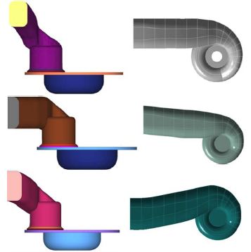 | Figure 1. Geometric model of IC Engine manifold |
2.1. Geometry Decomposition-Mesh Generation
In the literature, two approaches seem to be employed to solve in-cylinder problems, namely, hybrid approach and layering approach. While the hybrid approach is usually used for engines with canted valves like most of the SI engines, the layering approach is typically used for engines with vertical valves like most of the diesel engines. For either approach mentioned above, in-cylinder problem solved consist of three stages. The first stage is to decompose the geometry into different zones and mesh them properly. By breaking up the model into different zones, it is possible to apply different mesh motion strategies to different regions in a single simulation. The second stage is to set up the boundary condition inside Ansys Fluent. The third stage is to perform a transient in-cylinder simulation. The decomposition process is shown in Figure 2.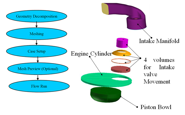 | Figure 2. Geometry decomposition of IC engine |
The following procedure was adopted for meshing the geometry. First, the surface was meshed with triangular element. In order to resolve the turbulent boundary layer on the solid surfaces, it is best to have growing prismatic cells from the Valve surfaces. Finally the remaining region in the domain is filled with tetrahedral cells. No of elements used for all the strokes were approximately 0.25 million (Tetrahedral elements = 0.1 million & Hexahedral elements = 0.15 million). For the mesh generation special care was taken to the zones close to the walls. In the proximity of the crest the mesh was made finer than any other part of the domain. The domain was subdivided into growing boxes to make it easier to generate the grid. The choice for the elements has been both tetrahedral and hexahedral mesh volumes.The meshing methodology is shown in Figure 3.Total No of elements = 0.25 millions Tetrahedral elements = 0.1 millions Hexahedral elements = 0.15 millions 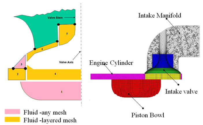 | Figure 3. Meshing Methodology |
2.2. Governing Equations
The continuity equation for unsteady, compressible flow and the standard k-epsilon turbulence model was taken into consideration for the present investigation.
2.3. Boundary Conditions
In this simulation, Pressure inlet boundary conditions were used to define the fluid pressure at flow inlets. The reference pressure was taken as 1 atmospheric. The engines walls were defined as stationary no slip walls. The flow was assumed fully developed. The turbulence intensity at the core of a fully-developed duct flow can be estimated from the following formula derived from an empirical correlation for pipe flows: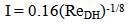 | (1) |
In this simulation, calculated Reynolds number was approximately 50,000, for this turbulence intensity of 4% was assumed. Hydraulic diameter was specified as inlet diameter of the manifold.The Boundary zones and Fluid zones are shown in the Fig. 4 and Fig. 5 respectively.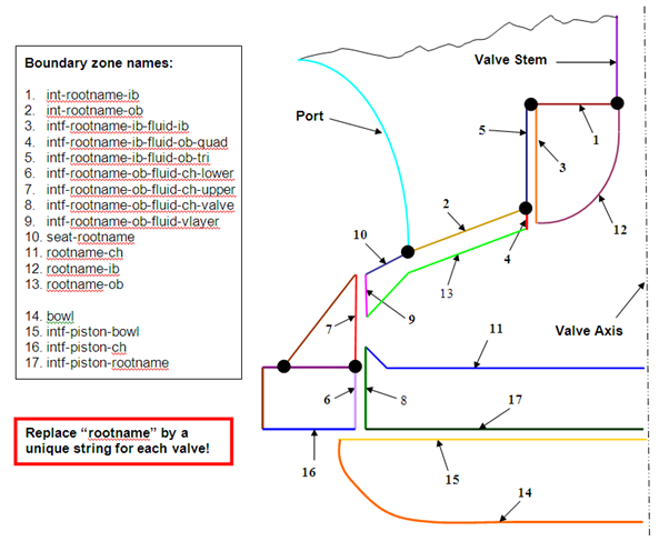 | Figure 4. Boundary zone names |
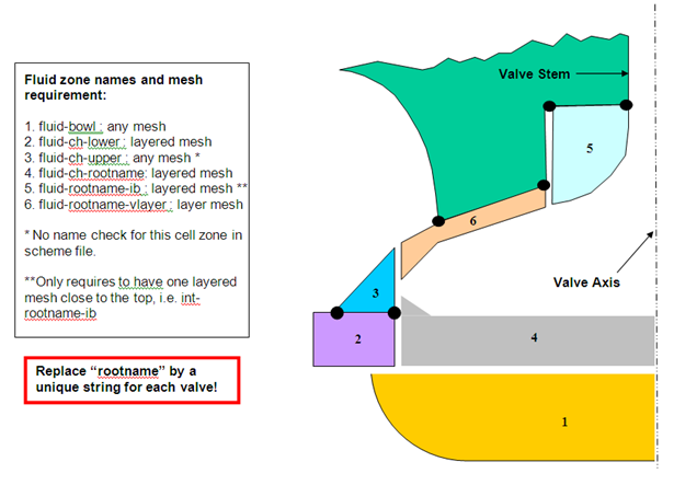 | Figure 5. Fluid zone names and mesh requirement |
The in-cylinder fluid dynamics in engines has been shown to play an important role during the combustion process. In particular, in-cylinder fluid flows contribute to fuel air mixing which is important to the fuel-burning rate. During the Intake process, the flow passing the valve separates and results in a highly unsteady motion. This flow contains both large-scale and small-scale turbulence. Since turbulence has a major effect on combustion, flow-mixing and on heat-transfer in an engine, to model the flow inside an engine a proper turbulence model should be used. In this analysis RNG k epsilon model was used. The moving mesh is generated by DYNAMIC MESH ROUTINE, a moving mesh module in FLUENT. In engine operation, valves and the piston move, so the mesh should move according to the real engine in order to simulate the charge of valve and piston position with crank angle. Piston and piston bowl movement are decided by the stroke, connecting rod and crank angle. Calculation starts at 360° (Crank angle) and ends at 108° (Crank angle). A cold flow analysis is performed for this purpose.Cold flow simulations for IC engines can provide valuable design information to engineers. This simulation allows for the effect on volume efficiency or swirl and tumble characteristics, to be predicted based on changes in port and combustion chamber design, valve lift timing, and other parameters.
3. Validation
Flow in IC engine cylinder with a straight inlet port and a valve lift of 10 mm (the distance from the top of the cylinder to the bottom of the valve) is examined in this case. The length of the cylinder is chosen to be large enough such that it will not affect the flow in the cylinder.Figure 6 and Figure 7 shows configuration of the inlet port, valve and cylinder with lines of measurements of the velocity. The port axis offset from the cylinder axis by 4mm in x-direction and 21.87mm in y-direction. The cylinder bore D=93.65mm and the valve diameter is d=43.00mm.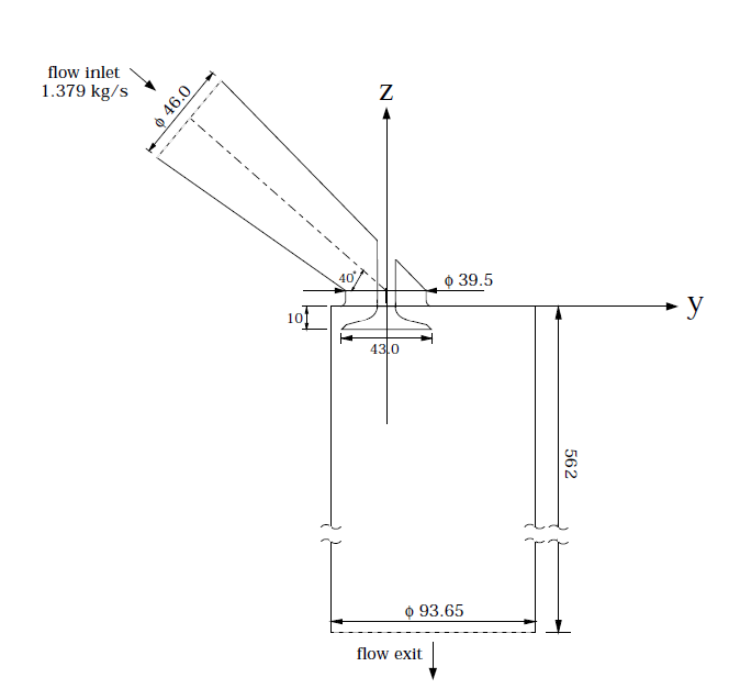 | Figure 6. Geometry of Engine inlet manifold |
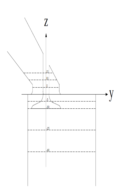 | Figure 7. Lines on which z-Velocity Measurements are taken |
The validity of the CFD code has been examined by comparing the Velocity profiles at different inlet manifold opening with the experimental results of Chen a et al, [2] and is shown in Fig 7a-7d. It is clear that Numerical flow results are in good agreement with experimental results.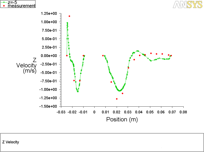 | Figure 7a. Comparisons of Z-Velocity measurements at z = -5 |
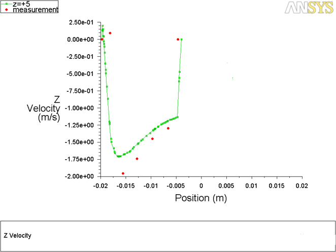 | Figure 7b. Comparisons of Z-Velocity measurements at z = +5 |
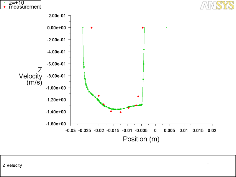 | Figure 7c. Comparisons of Z-Velocity measurements at z = +10 |
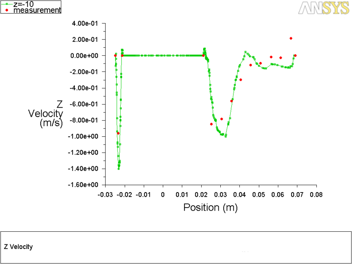 | Figure 7d. Comparisons of Z-Velocity measurements at z = -10 |
4. Results and Discussion
Figure 8 shows the variation of Swirl Ratio (SR) inside the cylinder with respect to crank angle for different manifold configurations at 1000 rpm. During the suction stroke, the swirl ratio increases till the maximum valve lift position and gradually decreases till the end of valve closing and again increases at the end of compression stroke. In the comparison of swirl ratio at 1000 rpm, maximum value is obtained for helical–spiral combined manifold configuration over the other two manifolds as the helical-spiral manifold is the combination of both spiral and helical so twisting effect will be more. This helps in better mixing of the Air-Fuel mixture.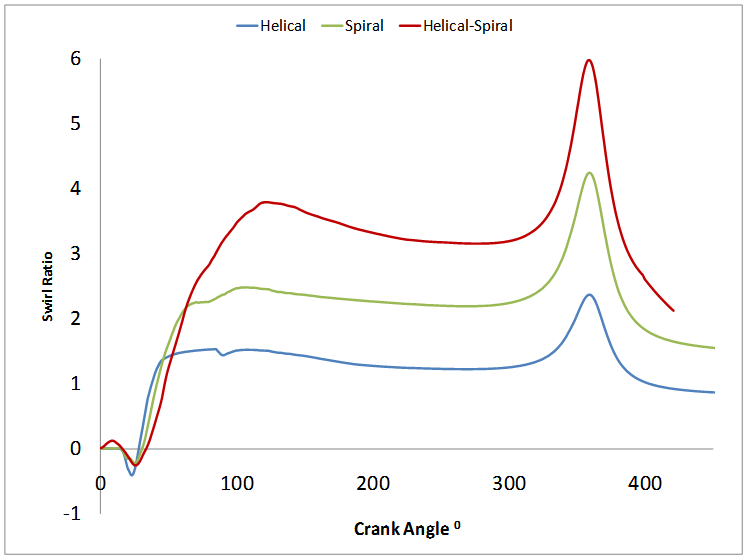 | Figure 8. Swirl ratios for different manifold configurations |
Figure 9 and 10 shows the variation of the tumble ratio (TR) with Crank Angle (CA) at 1000 rpm engine speed during suction and compression strokes. It was observed that the TR ratio changes its magnitude (positive to negative or vice versa) indicating overall air movement change in its direction during entire cycle with Crank Angle. The reasons for this could be: (i) change in the overall tumble flow pattern due to low pressure and bifurcation zones (ii) change in piston speed with CA and (iii) change in the direction of the piston movement during suction and compression strokes.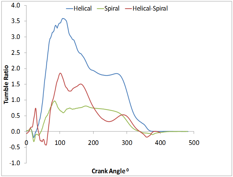 | Figure 9. Tumble ratios Y for different manifold configurations |
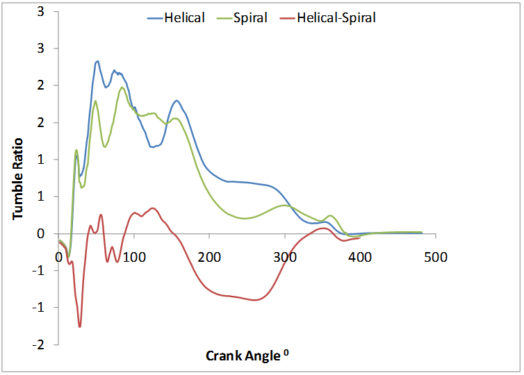 | Figure 10. Tumble ratios X for different manifold configurations |
With an increase in engine speed, variation in TR is marginal at all the CA. However, at 120° CA, TR was maximum. It can be concluded that stronger the tumble motion (more TR), more the turbulent kinetic energy released during its break down at the end of compression stroke. And this helps in higher turbulence levels at the time of ignition. And rate of combustion increases. Among the intake manifold shapes considered in this study, helical manifold results in higher TR compared to the Spiral and helical-spiral manifold.Figure 11 shows the variation of Turbulent Kinetic Energy (TKE) with crank angle at 1000 rpm for different manifolds. It is observed that the inlet manifold configuration affects the turbulence of the fluid inside the cylinder. It reaches the peak value during the maximum valve open condition. The variation of TKE is probably due to different level of air induced through the inlet manifold. The dissipation of KE is on account of increased fluid motion. Due to this, high Swirl Ratio is observed for helical-spiral combination than other manifolds with the corresponding low Turbulent Kinetic Energy level as shown in Figure 11.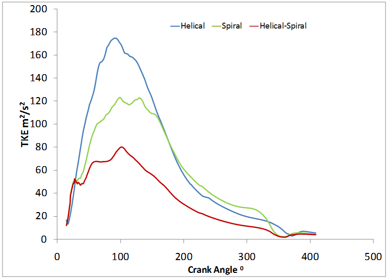 | Figure 11. Turbulent Kinetic energy for different manifold configurations |
Figure 12 shows volumetric efficiency for different manifold configuration. The spiral manifold has lower volumetric efficiency due to the flow restriction than other configurations. Also Turbulence consumes energy; hence swirl produced in the cylinder consumes energy. As spiral manifold has maximum swirl ratio, volumetric efficiency in this manifold is less. Higher volumetric efficiency is observed for helical manifold as there is very less restriction for the flow. Helical-spiral manifold has average volumetric efficiency and hence can be used for vehicles.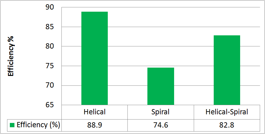 | Figure 12. Volumetric Efficiency for different manifold configurations |
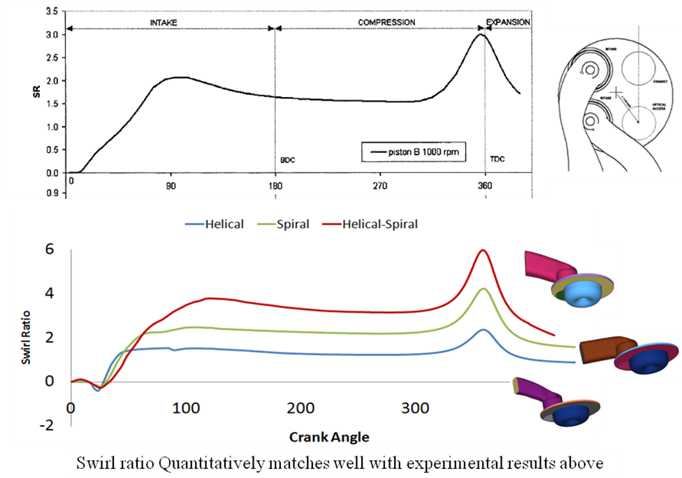 | Figure 13. Comparisons of intake manifolds on Swirl ratio |
5. Conclusions
In this project work, the flow characteristic in the intake manifold of a diesel engine was investigated computationally using Ansys Fluent 14.5 for three different geometries of the manifold (Helical, Spiral and Helical-Spiral). The governing equations for unsteady, three-dimensional, compressible, turbulent flow were solved using the two equation RNG k-ε model to consider the complexity of the geometry and fluid motion. The overall flow field inside the intake manifold and various quantities, such as swirl and tumble ratios were examined for all three types of manifold. The summary of the result is as follows:Ø Spiral and helical-spiral manifold creates higher swirl than Normal inlet manifold. In particular the helical-spiral combined manifold created higher swirl inside the cylinder as it is a combination of both spiral and helical & so the twisting action will be more.Ø Helical manifold results in higher TR & turbulent kinetic energy compared to the Spiral and helical-spiral manifold.Ø Volumetric efficiency was higher for helical manifold and average volumetric efficiency was observed for helical-spiral combination and hence can be suggested for use in the engines.
References
| [1] | Robert S. Laramee, Daniel Weiskopf, Jürgen Schneider, Avl Graz , Helwig Hauser, Investigating Swirl and Tumble Flow with a Comparison of Visualization Techniques, In Proceedings IEEE Visualization, V59 pp. 51-58, 2004. |
| [2] | Chen, A., Lee, K.C., Yianneskis, M., and Ganti, G., Velocity Characteristics of Steady Flow Through a Straight Generic Inlet Port, International Journal for Numerical Methods in Fluids V21, pp 571–590, 1995. |
| [3] | Benny Paul1, V. Ganesan, Flow field development in a direct injection diesel engine with different manifolds, International Journal of Engineering, Science and Technology V2, 2010. |
| [4] | W.H. Kurniawan, S. Abdullah., Turbulence and Heat Transfer Analysis of Intake and Compression Stroke in Automotive 4-stroke Direct Injection Engine, Algerian Journal of Applied Fluid Mechanics, V1, 2007. |
| [5] | S. L. V. Prasad, V. Pandurangadu, V. V. Prathibha bharathi and V. V. Naga deepthi, Experimental study of the effect of air swirl in Intake manifold on diesel engine performance, International Journal of Multidisciplinary Research & Advances in Engg.(IJMRAE), V3, pp. 179-186, 2011. |
| [6] | J. David Rathnaraj and Prof. T. Michael. N. Kumar, "Studies on variable swirl intake system for DI diesel engine using CFD", Thermal Science: V12 pp. 25-32 2008. |
| [7] | B. Murali Krishna and Mallikarjuna J. M, “Characteristics of flow through the intake valve of a single cylinder engine using practical image velocimetry Journal of Applied Fluid Mechanics, V3, pp. 23-32, 2010. |
| [8] | S.C. Kale and Prof. V. Ganesan, "A study of steady flow through a SI engine intake system using CFD”, Journal of the Institution of Engineers (India). V86, pp. 61-65.1996. |
 Abstract
 Reference
 Full-Text PDF
 Full-text HTML