-
Paper Information
- Paper Submission
-
Journal Information
- About This Journal
- Editorial Board
- Current Issue
- Archive
- Author Guidelines
- Contact Us
American Journal of Fluid Dynamics
p-ISSN: 2168-4707 e-ISSN: 2168-4715
2013; 3(2): 40-47
doi:10.5923/j.ajfd.20130302.04
Numerical Study of Lid-Driven Square Cavity with Heat Generation Using LBM
 Abstract
 Reference
 Full-Text PDF
 Full-text HTML
M. A. Taher1, S. C. Saha2, Y. W. Lee3, H. D. Kim1
1Dept of Mechanical Engineering, Andong National University, Andong, Korea
2School of Chemistry, Physics & Mechanical Engineering, Queensland University of Technology GPO Box 2434, Brisbane, QLD 4001, Australia
3Dept of Mechanical Engineering, Pukyong National University, Busan, Korea
Correspondence to: H. D. Kim, Dept of Mechanical Engineering, Andong National University, Andong, Korea.
| Email: |  |
Copyright © 2012 Scientific & Academic Publishing. All Rights Reserved.
In this study, the mixed convection heat transfer and fluid flow behaviors in a lid-driven square cavity filled with high Prandtl number fluid (Pr = 5400, ν = 1.2×10⁻⁴ m2/s) at low Reynolds number is studied using thermal Lattice Boltzmann method (TLBM) where ν is the viscosity of the fluid. The LBM has built up on the D2Q9 model and the single relaxation time method called the Lattice-BGK (Bhatnagar-Gross-Krook) model. The effects of the variations of non dimensional mixed convection parameter called Richardson number(Ri) with and without heat generating source on the thermal and flow behavior of the fluid inside the cavity are investigated. The results are presented as velocity and temperature profiles as well as stream function and temperature contours for Ri ranging from 0.1 to 5.0 with other controlling parameters that present in this study. It is found that LBM has good potential to simulate mixed convection heat transfer and fluid flow problem. Finally the simulation results have been compared with the previous numerical and experimental results and it is found to be in good agreement.
Keywords: Lattice-Boltzmann, Richardson number, Lid-driven, Heat generation
Cite this paper: M. A. Taher, S. C. Saha, Y. W. Lee, H. D. Kim, Numerical Study of Lid-Driven Square Cavity with Heat Generation Using LBM, American Journal of Fluid Dynamics, Vol. 3 No. 2, 2013, pp. 40-47. doi: 10.5923/j.ajfd.20130302.04.
Article Outline
1. Introduction
- In the recent years, the fluid flow and heat transfer in a driven cavity have received increasing attention because of its wide applications in engineering and physical sciences. Some of these applications include oil extraction, cooling of electronic devices and heat transfer improvement in heat exchanger devices. The Lattice Boltzmann Equation (LBE) is one of the methods available to deal with such problems effectively and efficiently. It is commonly recognized that the Lattice Boltzmann Method (LBM) can confidently be used to simulate the incompressible Navier-Stokes(N-S) equations with high accuracy. In this lattice BGK (LBGK) model, the local equilibrium distribution has been chosen to recover the N-S macroscopic equations by[1,2]. In addition, sometimes it is important to investigate thermal effects simultaneously with the fluid flows. Obviously the temperature distribution in a flow field is of central interest in heat transfer problems. In most geophysical flows, the temperature difference is the driving mechanism of the motion of the fluid.From a practical point of view, the research on natural and mixed convection in a cavity has been widely investigated[3,5]. The effect of inclination angle on heat transfer rate and flow pattern inside a lid-driven square cavity with different mixed convection parameter has been studied by Darzi et al.[6]. In their study they have shown that, the verity of Nusselt number and Richardshon number are opposite because the natural convection changes to mixed convection or forced convection when Richardson number decreases. Consequently, the Nusselt number increases.Hussein et al.[7] have investigated mixed convection through a lid-driven air filled square cavity with a hot wavy wall. The application of the thermal LBM to the natural convection flow in a square cavity with differentially heated wall with a uniform heat flux have been discussed by D'Orazio et al.[8]. Mohammad et al.[9], Dixit et al. [10] discussed a thermal lattice Boltzmann method based on the BGK model. They used this model to simulate high Rayleigh number natural convection in a square cavity. Patil et al.[11] showed that the LBM can be successfully applied in deep cavities with aspect ratios 1.5 to 4 with high Reynolds number. Prandtl number effects on MHD flow at a lid-driven cavity considering porous media have been numerical investigated by Hasanpour et al.[12].Various numerical simulations have been performed using different thermal LB models or Boltzmann based scheme to investigate the mixed convection flow problems as well as heat transfer related issues with different conditions[13-17]. He et al.[18] have discussed more details about thermal model for the LBM in incompressible limit. In this model, they have calculated temperature using an internal energy distribution function, where the macroscopic density and velocity are still simulated using density distribution functionIn addition, the thermal Lattice Bhatnagar-Gross -Krook (TLBGK) model with some adjustable parameters with Boussinesq approximation has been discussed by White et al.[19]. The more details TLBM with some examples are discussed by many authors[20- 26]. In this study, the problem of mixed convection in a lid-driven cavity filled with higher Prandtl number fluid (Pr = 5400, ν = 1.2×10⁻⁴ m2/s) and considering heat source placed at the middle position of bottom wall is investigated by using Thermal Lattice Boltzmann Method (TLBM). A few investigations of mixed convection in a cavity with upper moving lid, using TLBM, are found in the literature, but to the author’s knowledge, the above mentioned problem has not been studied yet by this method. The aim of the present study is to examine the effects of mixed convection parameter, called Richardson number (Ri), in presence of heat generating source at the bottom wall to investigate its effect to the fluid flows and temperature fields.
2. Problem Formulation
2.1. Mathematical Analysis
- To ensure the model satisfies the N-S equations for a fluid under the influence of body force, the most common form of Lattice Boltzmann Equation (LBE) with BGK approximation can be written as
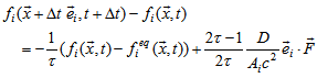 | (1) |
 is the particle distribution function and
 is the discrete equilibrium distribution function at lattice position
  and time t with lattice velocity vector
  discussed by[2]. Here Ai is the adjustable coefficient, D is the dimension, F is applied force, and ω =1/τ is the relaxation parameter that depends on the local macroscopic variables
  and
and . These variables should satisfy the following laws of conservation:
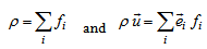 | (2) |
 | (3) |
 . The form of this equilibrium distribution function must be chosen so that the fluid mass and momentum are conserved. For two dimensional D2Q9 model, the equilibrium distribution function is defined by[2]
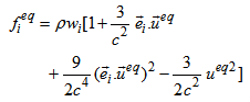 | (4) |
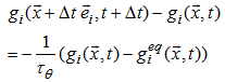 | (5) |
 is the relaxation time constant for energy equation. The energy distribution functionat the equilibrium state can be written as
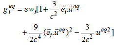 | (6) |
 is the internal energy variable of the fluid components and is defined as
 | (7) |
 . To improve the numerical stability, space-time independent average value of T is used to calculate the lattice speed
 . Under this assumption, the fluid corresponds to the ideal gas equation of state, PV = RT, with specific heats cv =1.0, cp=2.0, and with the adiabatic exponent γ = cp / cv = 2.0. So the R = cp – cv =1 in lattice units. It is known that the above equations recover the N-S equations both for velocity and temperature fields[2, 5], if the viscosity coefficient μ and thermal conductivity κ can be identified as
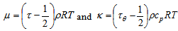 .These can be write in lattice unit as
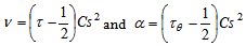 respectively. Here υ =μ/ρ is the kinematic viscosity of the fluid, α = κ /ρcp is the thermal diffusivity, and
  is the speed of sound in lattice unit. Therefore, the mean temperature of the fluid in this model can be written as
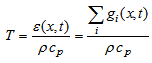 | (8) |
2.2. Numerical Analysis
- The physical configuration considered here as shown in Fig.1. is a closed square cavity of length H and filled with high Prandtl number fluid. The upper horizontal wall moves from left to right with a uniform velocity U∞, while the other three walls are fixed. The horizontal walls are assumed to be insulated whereas the vertical walls are maintained at constant but different temperatures Th (hot) and Tc (cold). A solid block or thin heater is placed at the bottom wall.
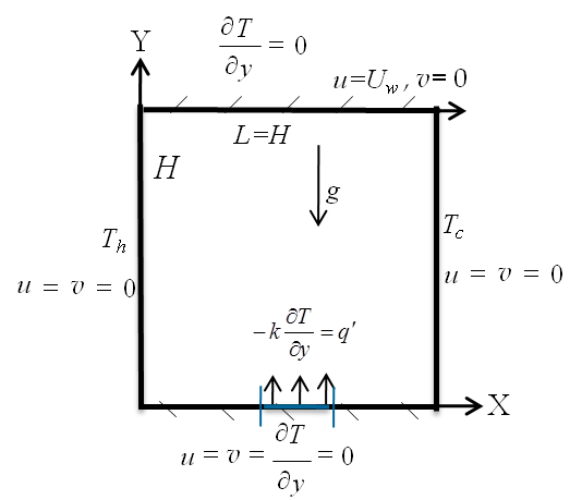 | Figure 1. The configuration of the problem under consideration |
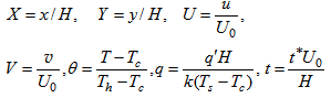
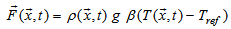 where Tref is the reference temperature of the fluid, g is the gravitation acceleration, β is the thermal expansion coefficient. For small temperature difference, the buoyancy force is balanced by viscous drag and heat dissipation. The ratio of the buoyancy force to the product of viscous force and heat diffusion rates defines the Rayleigh number
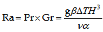 ,where Gr = gβΔTH3/ν2 is the Grashof number, Pr = ν/α is the Prandtl number, The ratio Gr/Re2 is the mixed convection parameter and it is called the Richardson number (Ri). Actually, it is a measure of the relative strength of the natural convection to forced convection for a particular problem.
 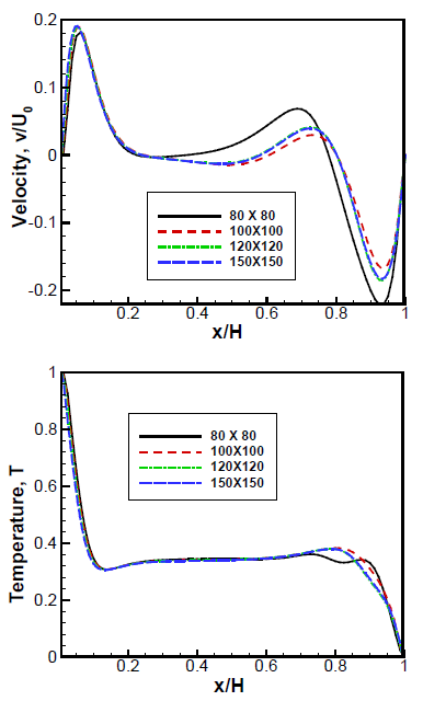 | Figure 2. Grid refinement test: V-velocity and temperature profiles along horizontal centreline of lid–driven cavity for different grid resolutions namely, 80×81, 100×101, 120×120 and 150×150 |
 The boundary conditions for the present study are as follows:
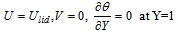
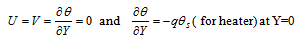
 and
and  where t* is the lattice time steps, q is the non dimensional heat generation parameter or heat source,
  is surface temperature of the heater and
  is the non dimensional temperature of the heat source. The characteristic speed
 must be chosen carefully(less than about 0.1), so that the low Mach number approximation holds in order to insure the problem is in the incompressible regime.
3. Results and Discussions
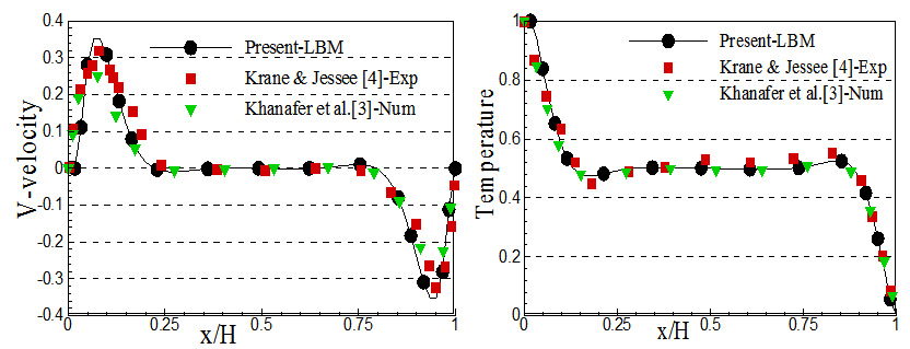
- By solving Eqs.(1) and (5), we will get all information that we are interested in our study. These equations are solved using two-dimensional uniform grid system along with boundary conditions and other equations described as above. Each numerical time steps consists of three stages: (i) collision, (ii) streaming, and (iii) boundary conditions followed by the LBM approaches. In order to validate our model, first, we verified our computational results with the conventional benchmark and experimental results as shown in the Fig.3. The present simulation has been shown against the numerical results of Khanafer et al[3] and the experimental results of Krane and Jessee[4] for natural convection in an enclosure filled with air as shown in Fig.3. It can be seen from these figures that our present numerical simulation is in very good agreement with both of numerical and experimental solutions. The velocity and temperature profiles have been depicted for Richardson number, Ri and heat generating source, q as shown in Figs. 4-5. The vertical velocity component, V is calculated along the horizontal centre line (see Fig 4) and the horizontal component, U is calculated along the vertical centre line of the cavity (see Fig 5). It is found that the fluid adjacent to the hot wall receives heat from the hot surface and rises due to buoyancy along the hot wall and fluid adjacent to the cold wall becomes colder and falls along the cold wall due to density variation, as expected in Fig.4(a). In more details, the velocity along the vertical walls of the cavity shows a higher level of activity as predicted by thin layer of hydrodynamic viscous boundary layers. The locations of the local maximum and minimum velocities for all cases tend to near the walls with increasing Ri. However, in presence of heat source(q = 0.05), local maximum velocity increases near the hot wall with increasing Ri. Therefore, the effect of buoyancy forces as well as heat generation with moving lid causes the strong fluid motion from left to right and consequently near the cold wall the fluid motion seems not laminar. From Fig.5, it is seen that the horizontal velocity, U, is zero at Y=0 and it decreases as Y increases, so that it becomes negative. For higher values of Y, U increases and approaches to its maximum value at upper part of the cavity where the top surface is moving horizontally.The effect of dimensionless temperature profiles with Ri at the centreline of the cavity as shown in Fig. 6. The temperature is calculated along the horizontal centre line. Fig. 6(a) represents the temperature profiles without heat generation and Fig. 6(b) represents temperature profiles with effect of imposed heat generation. It is revealed that the variation of temperature near hot and cold walls versus dimensionless horizontal length is linear for all Ri, which is the characteristic of heat transfer by convection, whereas, a significant temperature gradient is observed in the vicinity of the heated surface approximately, 0 ≤ X ≤ 0.20, and unheated surface 0.85 ≤ X ≤ 1. Moreover, it is seen that thermal stratification and increase in temperature in the direction of heat flow in the core region 0.20 ≤ X ≤ 0.85. Its physical meaning is that the temperature should decrease in the increase of Ri. It means that the natural convection is dominant compare to forced convection. This is because the upper wall is moving with constant velocity from left to right and therefore, the fluid motion enhances the rate of heat transfer. Without heat generation effect, the thermal boundary layers are seen both left and right walls (Fig.6a) but in Fig.6(b) it is seen just on left wall. Temperature contours and streamlines are shown in Fig. 7 and Fig. 8 respectively for different Richardson number, Ri and heat generation parameters, q. In Fig. 7, when Ri = 0.5, the heat is transferred mainly by forced convection between the hot and cold walls, but in presence of heat generation with moving lid, the temperatures contours inside the cavity tend to concentrate at the right vertical cold wall. In this case, thermal boundary layer is observed near both the hot and cold walls. It is also observed that heat transfer reduces when the forced convection dominated due to presence of heat generation and moving lid. Similar phenomenon is seen for Ri = 1.0. When Ri = 5.0, we see that the natural convection dominants the heat transfer. In this case both in absence or presence of heat generation, buoyancy force significantly enhances the heat transfer due to moving lid as well as heat generation source effects.The streamlines for different values of non dimensional mixed convection parameter with heat generation and without heat generation are shown in Fig. 8. In the absence of heat generation with increasing Ri, Figs.8(i)-(iii)(a), two primary vortices are seen. Since the natural convection becomes dominant with the increasing of Ri, near the right wall vortex approaches larger due to the combined effects of moving lid. With increasing the values of heat generation parameter, q> 0.01, two primary vortices become a larger central vortex as heat generation assists buoyancy forces by accelerating the fluid flow and the vortex centre moves with different values q. In addition, the secondary vortices are observed, one is near the top right corner and another one is bottom left corner for Ri=0.5 due to effect of moving lid as well as heat generating source at the bottom wall.
 | Figure 3. Comparison of velocity and temperature profiles for Pr = 0.71, Ra = 1.89105 |
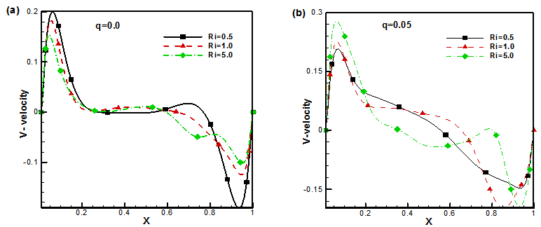 | Figure 4. V-velocity profiles along horizontal centreline of the cavity |
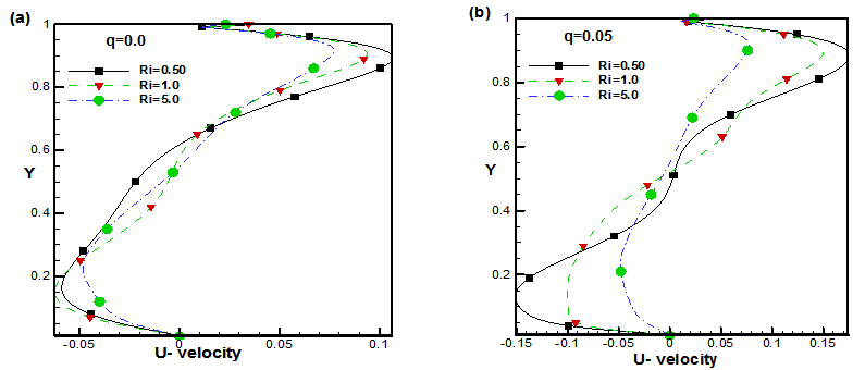 | Figure 5. U-velocity profiles along vertical centreline of the cavity |
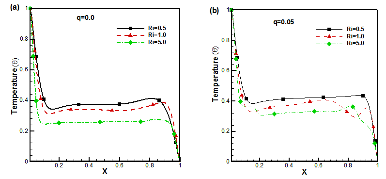 | Figure 6. Temperature profiles along horizontal centreline for Ri (a) with no generation (b) with heat generation |
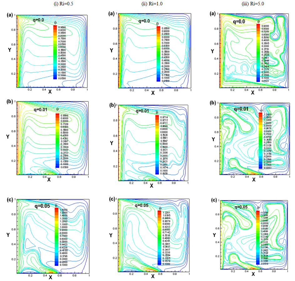 | Figure 7. The temperature contours for (i) Ri=0.5, (ii) Ri=1.0 and (iii) Ri=5.0, q= 0.0, 0.01 , 0.05 |
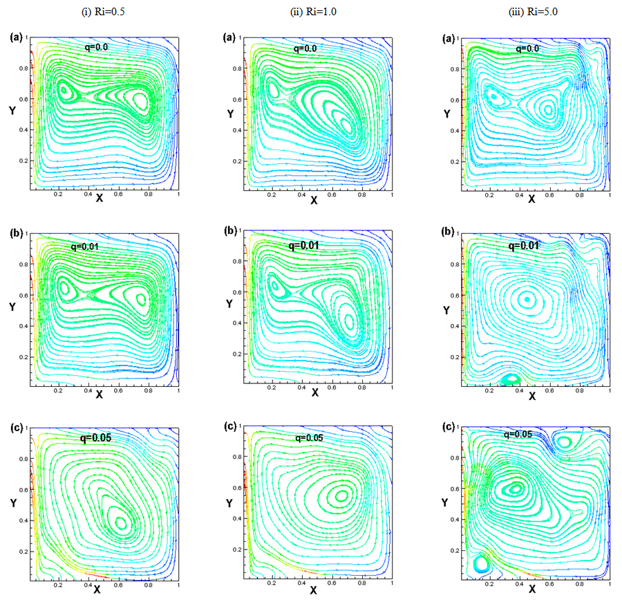 | Figure 8. The streamlines contours for (i) Ri=0.5, (ii) Ri=1.0 and (iii) Ri=5.0 with q= 0.0, 0.01, 0.05 |
4. Conclusions
- The convection heat transfer characteristics and flow performance of high Prandtl number fluid in a lid driven square cavity have been numerically investigated using TLBGK model. In this study, the mixed convection parameter (Ri) provides a measurement for the importance of the thermal natural convection forces relative to the mechanically induced lid-driven forced convection as well as heat generation (q) effect.We may summarize the findings from the above numerical investigation as follows:• The influenced of heat generation on fluid flow and heat transfer are more significant for natural convection dominating (Ri = 5) case compare to mixed and forced convection dominating cases (Ri=0.5, 1).• For Ri = 0.5 and Ri = 1.0, the overall heat transfer decreases as the buoyancy force and the motion of cavity are not in the same direction, however it is increased with increasing the values of heat generation parameter.• The overall heat transfer increases due to moving lid in presence of heat generation for natural convection dominating case, Ri = 5.• For Ri = 0.5 and Ri = 1, the two primary vortices merge and form a larger central vortex if the values of heat generation (q) increase since heat generation assists buoyancy forces by accelerating the fluid flow and the vortex moves with increasing heat generation. Moreover, for natural convection dominating case (Ri = 5.0), the secondary vortices are observed due to effects of moving lid as well as heat generating source at the bottom wall.