Saeid Maddah Kolur1, Fereshteh Kolahdouzan1, Amid Pahlavan1, Vijay P. Singh2, Hossein Afzalimehr1
1Department of Civil Engineering, Iran University of Science and Technology, Tehran, Iran
2Department of Biological & Agricultural Engineering & Zachry Department of Civil and Environmental Engineering, Texas A&M Univ., College Station, Texas, USA
Correspondence to: Hossein Afzalimehr, Department of Civil Engineering, Iran University of Science and Technology, Tehran, Iran.
| Email: |  |
Copyright © 2021 The Author(s). Published by Scientific & Academic Publishing.
This work is licensed under the Creative Commons Attribution International License (CC BY).
http://creativecommons.org/licenses/by/4.0/

Abstract
In this study, scouring around single and double piggyback pipelines in different arrangements was experimentally investigated in a laboratory flume. Two diameter ratios of small pipe diameter (d) to large diameter pipe (D) (d/D) = 0.2 and 0.3 were used. The effect of change in arrangement of piggyback pipelines on the scour depth in live-bed condition was evaluated using the Young et al. criterion. Results showed that the change in arrangement, regardless of the number of piggyback pipelines, significantly reduced the maximum scour depth, and the larger d/D ratio was, the greater was the scour depth reduction.
Keywords:
Piggyback pipeline, Scour depth, Different arrangements, Live–bed condition
Cite this paper: Saeid Maddah Kolur, Fereshteh Kolahdouzan, Amid Pahlavan, Vijay P. Singh, Hossein Afzalimehr, Experimental Investigation of Scouring around Piggyback Pipelines in Different Arrangements, American Journal of Environmental Engineering, Vol. 11 No. 1, 2021, pp. 16-20. doi: 10.5923/j.ajee.20211101.03.
1. Introduction
Marine pipelines are important for transporting water, natural gas, oil, and petroleum products. In recent decades, a new form of marine pipeline, called piggyback pipeline, has been developed. This type of pipeline consists of a large pipe and a small pipe that is installed directly above the large pipe. This type of pipeline is suggested, because it is difficult to monitor the amount of oil remaining in the pipelines after a period of transfer operation, and on the other hand, the accumulation of oil residues in the pipeline leads to blockage or wastage of oil [2]. In this way, the large pipeline carries oil or gas, while the small pipeline carries the monitoring signal and oil transport materials [3]. Such a pipeline addresses the problem of oil loss and improves the economic efficiency of oil fields [4]. In the phase 12 of Southern Pars project in Iran, three 32-inch pipelines have been used to transfer gas from the platform to the beach and to each one a 4-inch pipeline has been connected.A number of studies conducted on the effect of various factors and parameters on scouring under this type of pipeline have shown that the width and depth of the scouring hole around the piggyback pipeline is greater than that around a single pipe under similar laboratory conditions [5]. In a numerical study, Zhao (2012) [6] investigated the effect of changing the location of small pipe relative to the large one on the formation of vortices behind the pipeline and scour depth. Their results showed that the maximum scour depth occurred when  = 90° and the minimum scour depth occurred when
  = 0° or 90° (Figure 1).
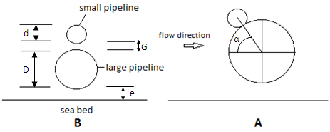 | Figure 1. Definition of parameters in piggyback pipeline |
Also, investigations of the effect of different distances between pipeline and bed (e) showed that the maximum scour depth below the piggyback pipeline occurred when the distance of the large pipe from the bed was e = 0.15D [6] [7] [8] [9]. It has been shown that when the small pipe was placed on the large pipe without distance (G/D = 0), maximum scour depth occurred and as this distance increased, the maximum scour depth and its time duration decreased [10]. [Define G, e] When G/D>0.4 where G is a gap between pipelines, the impact of small pipe on the main pipe decreased and the maximum scour depth below the pipeline approached the maximum scour depth of a single pipe [5]. Yang et al (2019) [1] proposed a model of "one large diameter pipe in the middle and two smaller pipes on the sides" instead of "one pipe stacked on top of another pipe" due to the disadvantages of the piggyback pipeline in terms of increasing scour depth. (Figure 2). They reported that this new pipeline effectively reduced the pressure gradient between upstream and downstream of the pipeline, which led to a reduction in scour depth around the pipeline. They also found that when the diameter ratio of the pipes increased, the pressure gradient decreased. 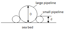 | Figure 2. Arrangement suggested by Yang et al (2019) [1] |
The objective of this technical note is to answer the following questions:What is the effect of diameter ratio on the scour depth for a single piggyback pipeline?How is the scouring depth affected by changing the piggyback pipeline arrangement?
2. Experimental Setup and Procedure
The flume used in this experimental study had a length of 13 m, width 0.46 m and depth 1 m, and its maximum capacity was 440  . At the entrance of the flume, 1 m long galvanized mesh sheets were stacked on the top of each other to reduce the distance needed for reaching fully developed flow. The distance between 8.75 m and 10.25 m from the entrance of flume was selected as the test site and the models were placed in the middle of it. For this interval, sand with
  = 0.24 mm with a geometric standard deviation of less than 1.4 mm was used, and in other parts, sand with
  = 1.9 mm was used, which had no particle movement during the test. The height of bed sediments was 20 cm. In all experiments, a uniform flow with a depth of 260 mm and an average velocity of
 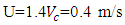 was used for live-bed conditions. The critical velocity
  was 0.287 m/s, calculated following Melville and Sutherland (1988) [11].To prevent the pipes from moving under the influence of currents, a rubber sheet was placed on one side between the pipe and flume wall and the pipes do not move during the tests. All experiments were continued until the scour depth did not change more than 1 mm over a two-hour period.Yang et al. (2019) [1] proposed and examined a combination of two small pipes and a large pipe under clear-water conditions. Their experiments were performed on four-pipe combinations as d/D = 0.1, 0.2, 0.25, 0.3 (d is the small pipe diameter and D is the large pipe diameter). In this study, two pipe combinations d/D = 0.2 and 0.3 (combination of two pipes (0.5 cm, and 2.5 cm) and (1.2 cm and 4 cm) were used. Like Yang et al (2019) [1], small and large pipes are connected to each other without distance. (Figure 3)To do experiments, first, a single pipe with a diameter of 2.5 cm was examined. Then, piggyback pipelines were investigated (similar to the experiments of Yang et al. (2019) [1]), herein the live-bed conditions with two arrangements were compared. In the next step, the effect of change in the arrangement of piggyback pipelines on double-pipe system was investigated (Figure 3).
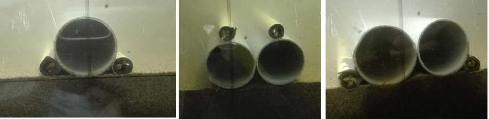 | Figure 3. Arrangements of piggyback pipelines |
3. Dimensional Analysis
The most important parameters that affect scouring under pipelines can be summarized as follows: | (1) |
where U is the average flow velocity, H is the flow depth, S is the bed slope,  is the density of fluid, g is the gravity acceleration,
  is the kinematic viscosity, D is the pipe diameter, G is the distance between pipes in pipe group, d is the small pipe diameter in piggyback pipes,
  is the median size of sediment,
  is the geometric deviation of sediment, and
  is the density of sediment. Using Buckingham theory, Equation 1 can be written as follows:
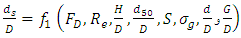 | (2) |
The Reynolds number  can be calculated by Equation 3, and however, it may be omitted because all experiments were carried out in turbulent flow. Also, considering Dey and Singh (2008) [12], when
  , scouring under the pipe is independent of flow depth, so
  in Equation 2 was not used in this study. In equation (2), S and
  were constant during the experiments and was removed from Equation 2 as well.
 | (3) |
According to the above considerations, Equation 2 was simplified as follows: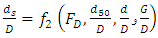 | (4) |
in which the Froude number ( ) was calculated using Equation 5:
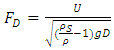 | (5) |
4. Hydrodynamic Forces
The hydrodynamic forces acting on the horizontal pipeline that is exposed to the flow are shown in figure 4. In this picture  W and
W and  are Drag force, Inertia force, Lift force, pipe submerged weight and soil resistance (soil-pipe friction force) respectively [13]. These forces for piggyback pipelines in two different arrangement are shown in figure 5.
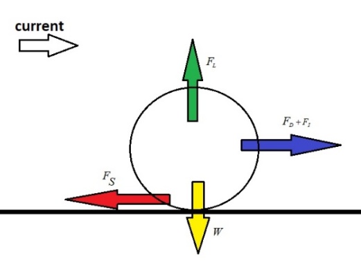 | Figure 4. The hydrodynamic forces acting on the horizontal pipe under flow |
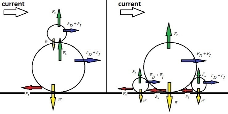 | Figure 5. The hydrodynamic forces acting on piggyback pipelines in two arrangement of this study |
5. Results
5.1. Single Piggyback Pipeline
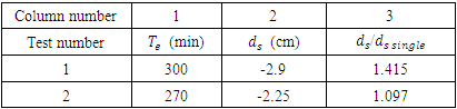
For comparing the results with the piggyback pipeline, a single pipe with a diameter of 2.5 cm was tested with a maximum scour depth of 2.05 cm in 180 min. Then, the effect of change in the arrangement of single piggyback pipeline with a diameter ratio of 0.2 on scour depth was investigated by two experiments. Figure 6 shows scour profiles in these two experiments. Results of these two experiments are shown in Table 1, and showed that by changing the piggyback pipeline layout, the time required to perform the test reduced and caused a 22.4% reduction in scour depth. In addition, the maximum scour depth under the piggyback pipeline with a diameter ratio of 0.2 in the first and second experiments was 41.5% and 9.7% higher than the maximum scour depth below the single pipe, respectively.Table 1. Results of Single Piggyback Pipeline Tests with d/D=0.2
 |
| |
|
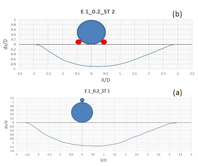 | Figure 6. Scour profiles of piggyback pipelines in a) test 1 b) test 2 |
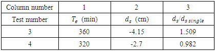
In the next two experiments, the effect of this change in arrangement on scour depth for single piggyback pipeline with a diameter ratio of 0.3 was investigated (Figure 7). Results of the two experiments are shown in Table 2. This table shows that at a diameter ratio of 0.3, similar to the diameter ratio of 0.2, the time required for the test reduced by changing the piggyback pipeline layout. This change in arrangement also reduced the maximum scour depth by 34.9%. Column 3 of Table 2 shows that the maximum scour depth in two arrangements was 50.9% higher and 1.8% less than the maximum scour depth of a single pipe, respectively.Results obtained from 4 experiments performed in this section for piggyback pipeline with a diameter ratio of 0.2 and 0.3 in live-bed conditions showed that the results presented by Young et al. (2019) [1] in clear-water conditions were true under live-bed conditions.Table 2. Results of Single Piggyback Pipeline Tests with d/D=0.3
 |
| |
|
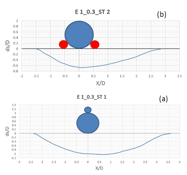 | Figure 7. Scour profiles of piggyback pipelines in a) test 3 b) test 4 |
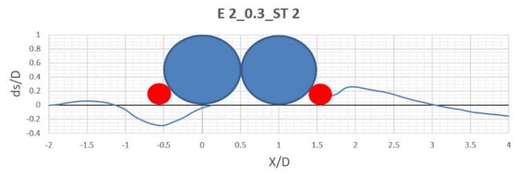
5.2. Double Piggyback Pipelines with no Gap between Pipelines
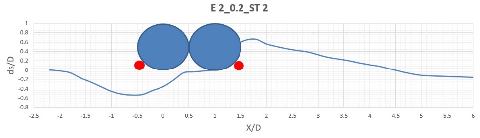
In the previous section, it was observed that a change in the location of small pipe relative to the large pipe in piggyback pipeline could significantly reduce the maximum scour depth below it. In this section, the effect of this change in arrangement was examined for double-piggyback pipeline mode. Similar to the previous part, in the first two experiments, a diameter ratio of 0.2 and in the third and fourth experiments, a diameter ratio of 0.3 was used for piggyback pipelines. In the first experiment, the maximum scour depth was 3.3 cm, which increased by 13.8% compared to the single piggyback pipeline experiment with a diameter ratio of 0.2. The test period was 360 min. In the second experiment, the scour hole was not formed completely under the two pipelines after 480 min and only under upstream pipe was washed. The maximum scour depth in the hole formed below the upstream pipe was 1.35 cm. The maximum scour depth in the third experiment was 4.55 cm, showing an increase of 9.64% compared to the single piggyback pipeline experiment. Also, the test time period was 420 min. In the fourth experiment, during 480 min, the scour hole was not completely formed under the two pipes and the maximum scour depth in the hole created under the upstream pipe was 1.15 cm. Figures 8, 9, 10 and 11 show the scour profiles in these 4 experiments. Comparison of figures 9 and 11 showed that the effect of changing the arrangement of double piggyback pipelines on reducing the scour depth for a diameter ratio of 0.3 was much more significant than for the diameter ratio of 0.2.Comparing the results obtained during the experiments of single and double piggyback pipelines, it was found that the effectiveness of this type of arrangement change was much higher for the double-pipe mode than for the single-pipe mode.Based on 8 experiments performed on piggyback pipelines, it can be concluded that a change in the arrangement of these pipelines, regardless of their number, significantly reduced the maximum scour depth below them, and as d/D ratio increased, the reduction of scour depth increased as well.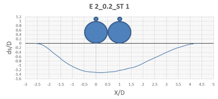 | Figure 8. Scour profile of double piggyback pipeline test with d/D=0.2 (first arrangement) |
 | Figure 9. Scour profile of double piggyback pipeline test with d/D=0.2 (second arrangement) |
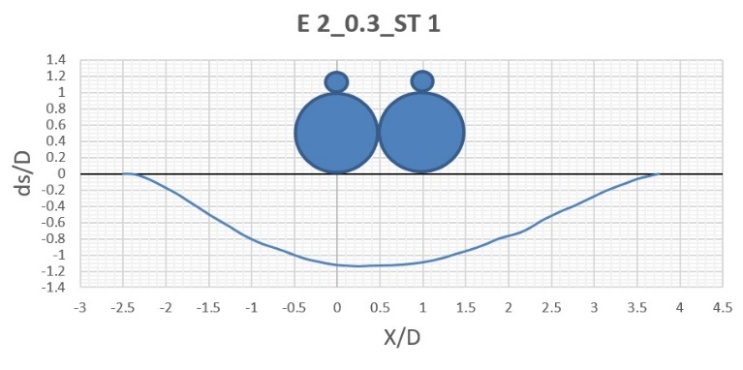 | Figure 10. Scour profile of double piggyback pipeline test with d/D=0.3 (first arrangement) |
 | Figure 11. Scour profile of double piggyback pipeline test with d/D=0.3 (second arrangement) |
6. Conclusions
In this study, 8 experiments were performed for single and double-piggyback pipelines and the effect of piggyback pipeline arrangement on scour depth was investigated. The following results were obtained:1- Results of 4 experiments performed for single piggyback pipelines, with a diameter ratio of 0.2 and 0.3 showed that by changing their arrangement, the scour depth has reduced by 22.4% and 34.9%, respectively.2- Changing the arrangement of piggyback pipelines in double-pipe experiments caused a significant reduction in scour depth. In such a way the scouring hole was formed only under the upstream pipeline.3- By changing the arrangement of piggyback pipelines, the hydrodynamic forces on the pipes also change. For example, in the new arrangement of pipelines, the frictional force between the pipes and soil is greater (due to more contact surface between pipes and bed), so it may be possible that reduction of scour depth in the new arrangement attributed the hydrodynamic forces acting on the pipes.
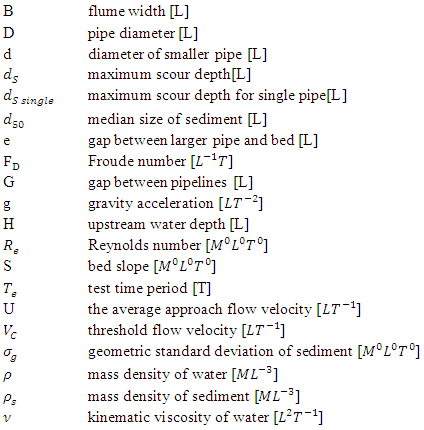
Notation
References
| [1] | S. Yang, B. Shi, Y. Guo, and L. Yang, “Investigation on scour protection of submarine piggyback pipeline,” Ocean Eng., vol. 182, pp. 442–450, Jun, 2019. |
| [2] | H. Yang and H. Ni, “An applicable replacement bundled pipeline structure for offshore marginal oilfield development,” Sh. Build. China, vol. 48, pp. 563–570, 2007. |
| [3] | M. . Jakobsen and P. Sayer, “Hydrodynamic forces on piggyback pipelines,” 5th Int. Offshore Polar Eng. Conf. Hague, Netherlands, vol. 1, pp. 139–147, 1995. |
| [4] | J. Brockbank, “Bundled pipe speed offshore laying,” Oil Gas J, vol. 88, no. 19, pp. 78–84, 1990. |
| [5] | S. Yang, B. Shi, and Y. Guo, “Investigation on scour scale of piggyback pipeline under wave conditions,” Ocean Eng., vol. 182, pp. 196–202, Jun, 2019. |
| [6] | M. Zhao, “Influence of the position angle of the small pipeline on vortex shedding flow around a sub-sea piggyback pipeline,” Coast. Eng. J., vol. 54, no. 3, 2012. |
| [7] | M. Zhao, L. Cheng, B. Teng, and G. Dong, “Hydrodynamic forces on dual cylinders of different diameters in steady currents,” J. Fluids Struct., vol. 23, no. 1, pp. 59–83, Jan. 2007, doi: 10.1016/j.jfluidstructs.2006.07.003. |
| [8] | M. Zhao, L. Cheng, and B. Teng, “Numerical modeling of flow and hydrodynamic forces around a piggyback pipeline near the seabed,” J. Waterw. Port, Coast. Ocean Eng, vol. 133, no. 4, pp. 286–295, 2007. |
| [9] | M. Zhao and L. Cheng, “Numerical modeling of local scour below a piggyback pipeline in currents,” J. Hydraul. Eng, vol. 134, no. 10, pp. 1452–1463, 2008. |
| [10] | E. Zhao, B. Shi, K. Qu, W. Dong, and J. Zhang, “Experimental and Numerical Investigation of Local Scour Around Submarine Piggyback Pipeline Under Steady Current,” Journal of Ocean University of China, vol. 17, no. 2. pp. 244–256, 2018. |
| [11] | Melville, B.W., and M. Sutherland, 1988. Design method for local scour at bridge pier. Journal of Hydraulic Engineering, 114(10): 70-82. |
| [12] | S. Dey and N. P. Singh, “Clear-Water Scour below Underwater Pipelines under Steady Flow,” J. Hydraul. Eng., vol. 134, no. 5, pp. 588–600, 2008. |
| [13] | Eferebo Ntubodia, Ibiba Emmanuel Douglas and Ezebuchi Akandu, “Comparison of On-Bottom Stability of Subsea Pipeline under Different Wave Spectra and Currents” American journal of engineering research, volume-8, issue-7, pp-98-110. |

 Abstract
 Reference
 Full-Text PDF
 Full-text HTML