-
Paper Information
- Next Paper
- Previous Paper
- Paper Submission
-
Journal Information
- About This Journal
- Editorial Board
- Current Issue
- Archive
- Author Guidelines
- Contact Us
American Journal of Environmental Engineering
p-ISSN: 2166-4633 e-ISSN: 2166-465X
2013; 3(6): 283-287
doi:10.5923/j.ajee.20130306.03
Turbidity Study of Sequential Siphon Sediment Basins
 Abstract
 Reference
 Full-Text PDF
 Full-text HTML
Moayyad Al-Nasra
Department of Engineering Technology, West Virginia University, Institute of Technology, Montgomery, WV 25136, USA
Correspondence to: Moayyad Al-Nasra, Department of Engineering Technology, West Virginia University, Institute of Technology, Montgomery, WV 25136, USA.
| Email: |  |
Copyright © 2012 Scientific & Academic Publishing. All Rights Reserved.
The Best Management Practice, BMP, provided several methods and procedures to reduce the turbidity, but failed to address the turbidity in terms of measurements and control. Several measures were proposed, and in many cases erosion and sedimentation measures are enforceable. New sediment basin design is used in this study. The main purpose of this study is to introduce new sediment basin design called siphon sediment basin. This sediment basin can be used as multi-leveled basin in order to reduce the turbidity to a predetermined level. The siphon sediment basin is proven to be economically advantageous compared to other sediment basins covered by the Best Management Practice manual. Maintenance of the siphon sediment basin is relatively easier and less costly.
Keywords: Sediment Basin, Siphon, Turbidity, Erosion, Sedimentation
Cite this paper: Moayyad Al-Nasra, Turbidity Study of Sequential Siphon Sediment Basins, American Journal of Environmental Engineering, Vol. 3 No. 6, 2013, pp. 283-287. doi: 10.5923/j.ajee.20130306.03.
Article Outline
1. Introduction
- Siphon sediment basin is not covered by the Best Management Practice, BMP, but its simplicity and efficiency are its main advantage compared with other sediment basins. The main purpose of the siphon sediment basin is to control turbidity at the same time it is considered as erosion and sedimentation device. A siphon can be a pipe connecting an upstream and high level pool of water to a downstream and lower level pool. The difference in elevation is called the hydraulic head. The weight of the water above the lower pool has the potential energy that can be used to cause the water to flow from the upper pool to the lower pool. The water in the pipe can reach a higher elevation than the higher pool. The energy in the water can be used to increase the velocity of flow in the pipe and thereby increase the rate of flow over that obtainable by letting the water free fall into a receiving channel or pipe. Chen et al[1] studied the high turbidity in raw water. Barrier board was used to extend the flowing route and to change the overflow level for carrying out the pre –treatment of high-turbidity raw water through the channel of varied flow rate in order to study the changes and removal rate of the turbidity for the influent and effluent. Their experimental results indicated that the turbidity of high-turbidity water can be reduced by means of inertia restrained flow, extending the flowing route, and heightening the overflow level.Liu et al[2] studied the turbidity measurement using the Poly (N-isopropyl acrylamide) shading agent systems containing Hydrophilic Vinyl Compounds additives. The turbidity measures were used to study the temperature sensitive behavior and the phase behavior of linear Poly (N-isopropyl acrylamide) in water-additive systems. Pollutant removal is a major issue that has been addresses by many researchers. Hidayah and Karnaningroem[3] studied the implementation of hydrodynamics model in water treatment to estimate turbidity removal. Mathematical model was constructed from two hydrodynamic equations, namely the continuity equation and momentum equation. Their research aimed to study mathematical models of settling flocks patterns in rectangular sedimentation tanks based on a specified hydrodynamic model mathematical formulation. Lewis[4] also studied the sediment load estimation. The study covered an automated procedure for measuring turbidity and sampling suspended sediment. The basic equipment consists of a programmable data logger, an in situ turbid meter, a pumping sampler, and stage-measuring device. The data logger program employs turbidity to govern sample collection during each transport event. To reduce turbidity in sediment basins, baffles can be used to increase the water pathway, McLaughlin[5]. Sediment traps and basins at construction sites, agricultural operations, and other unsettled areas provide temporary pools for runoff that allow sediment to settle before the water is discharged into a river, stream, or landscape. They prevent erosion and trap sediment and other coarse material. They are most effective in sandy soils and less effective in clayey soils. Unfortunately, these traps and basins are not efficient when the swift, turbulent water moves along a straight-line flow that takes runoff quickly to the basin’s outlet. This short-circuits interaction with the entire basin. Using baffles to slow, calm, and distribute the water can help solve this problem. Baffles can lengthen the flow path and distribute the flow more widely. They significantly increase the amount of sediment captured and also trap much smaller particles than open basins. A simple way to lengthen the flow path is to install solid baffles that force the water to move from side to side in the basin. These may be made of sturdy plywood or similar materials, usually with a notch or weir cut into the top at opposite ends to create a long, back-and-forth flow path. Silt fencing (or geotextile) has also been used because the material is sturdy, inexpensive and easy to install, and it is commonly available on construction sites. The geotextile is essentially impermeable for the kinds of flows expected in the basin. Hoechst[6] studied the efficiency of skimmers in comparison with perforated risers, and concluded that the effluent sediment concentrations were highest at the start of each run and then declined exponentially. There was no statistical interaction between outlet and soil type therefore the basin retention efficiency was not influenced by any particular combination of outlet and soil type. Shorter dewatering times may have less of an impact on retention efficiency when the skimmer is utilized than when the perforated riser is used thereby possibly requiring smaller sedimentation basin sizes.
2. Turbidity
- Turbidity is an indication of the amount of fine suspended particles in the water. These particles could be toxic material and harmful to marine life as well as human being. Turbidity is the cloudiness or haziness of a fluid caused by individual particles, suspended solids that are generally invisible to the naked eye, similar to smoke in air. One of the key tests of water quality is turbidity. Water can contain suspended solids matters of different particle sizes. The large and the heavy particles settle faster than the little and light particles. The very small particles will settle very slowly, and in some cases will not settle at all if the water is regularly agitated or the particles are colloidal. These small solid particles cause the water to appear turbid.There are several ways to measure the water quality. The most direct way is to measure the attenuation of light as it passes through a sample column of water. The suspended particles, in turn will scatter a light beam, which used as a measure of turbidity in water. The unit of turbidity is called Nephelometric Turbidity Unit, NTU. There is a direct correlation between the turbidity and the total dissolved solids in water. Figure 1 shows the device that measures the turbidity in water. Turbidity in open water is caused by growth of phytoplankton. Land disturbance due to urbanization, mining, and agricultural projects is one of the cause of turbidity in water. Turbidity can be used as a measure of water pollution which can be considered as health hazard. In addition, in water bodies such as lakes, rivers and reservoirs, high turbidity levels reduce the amount of light reaching lower depths affecting the growth of submerged aquatic plants and marine life.
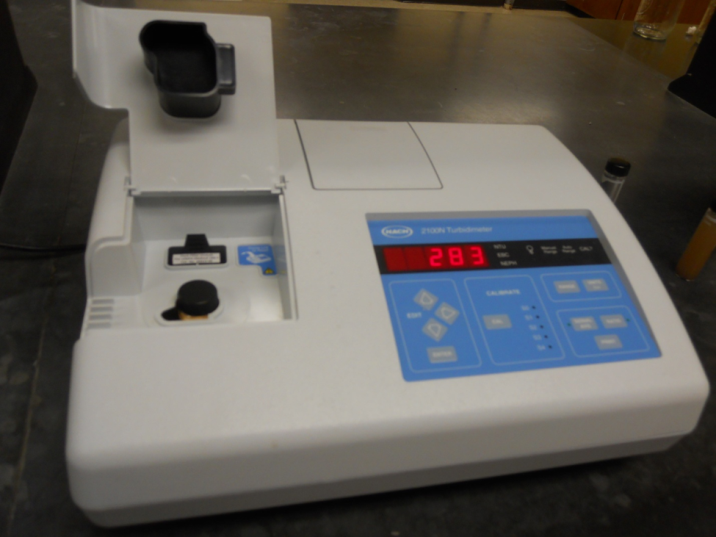 | Figure 1. Turbidity measuring device |
3. Siphon Sediment Basin
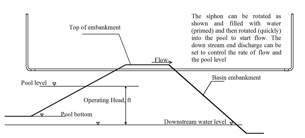
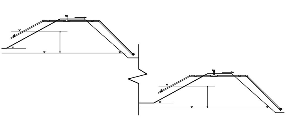
- One of the main functions of a sediment basin is to allow the suspended particles in the water to settle. Ultimately, the sediments of any site stay in the site without being transported to other neighboring sites. The size and type of any sediment basin is by design depending, mainly on the catchment area, land cover, topography, climate, and water runoff. Draining the sediment basin at the right time and the right location is a key to control water turbidity. Skimmers are used widely to drain the basin from the top water surface. At the top location the turbidity is at its lowest. But in many cases floating particles could be a problem. The skimmer is an expensive device, and difficult to maintain. This study introduces a new type of sediment basin called siphon sediment basin as shown in Figure 2. The siphon sediment basin is very inexpensive, composed mainly of PVC pipes than can be easily installed and maintained in minutes. In this figure one can see the operational features of the siphon. The flow capacity as shown is related to the operating head. When the siphon is used as a stilling basin, it is appropriate to attenuate the detention time in order to decrease turbidity of the discharge. The controlling operational judgment is determining the length of time to the next rainfall event. Figure 3 shows details of the intake strainer design.The siphon can be set low in the embankment, on top, or anywhere in between. The discharge pipe can be rotated to control the pool level and the rate of discharge. The siphon sediment basin also allows for draining the water at a designed elevation that can be variable depending on the particular need and the specific requirements of the sediment basin. Two different configurations of the siphon sediment basin are shown in Figure 4 and Figure 5.
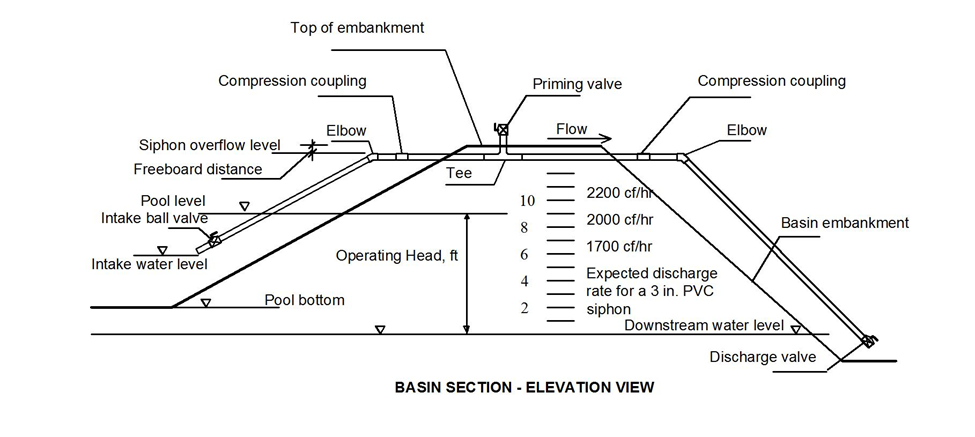 | Figure 2. Siphon sediment basin |
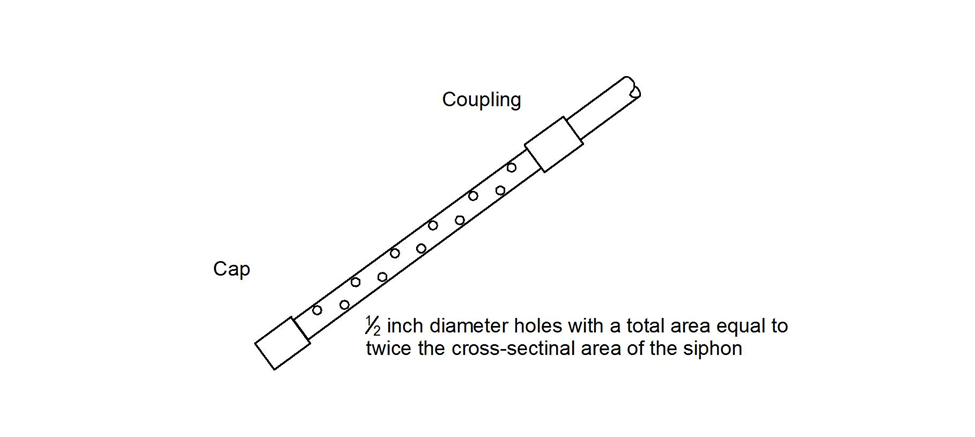 | Figure 3. Intake strainer design |
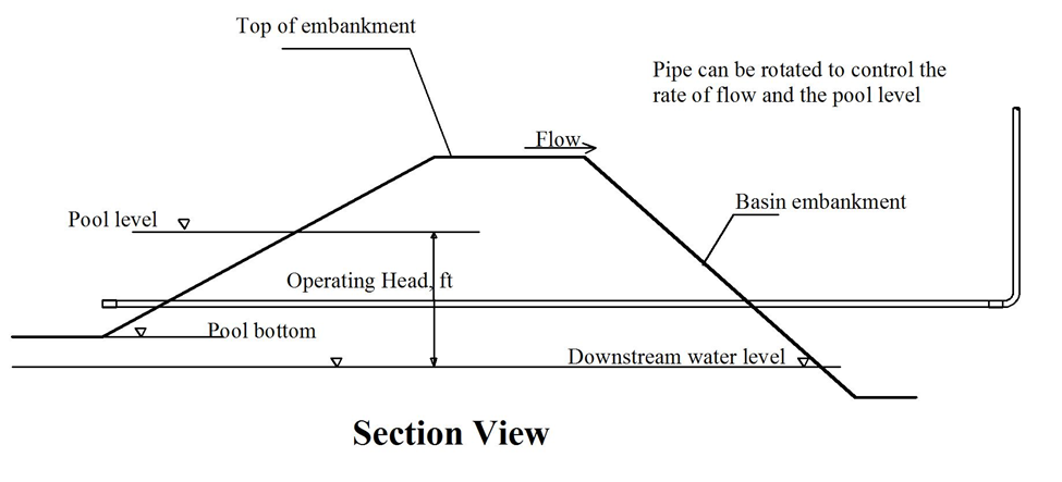 | Figure 4. Siphon set at bottom of the embankment |
 | Figure 5. Siphon set at top of the embankment |
4. Multi-Level Siphon Sediment Basin
- Figure 6 shows the configuration of the multi-level siphon sediment basin. The number of basins needed is determined by the final turbidity measure at the last basin outflow. Low turbidity required more basins. This concept is very similar to the detention ponds, and retention ponds, where the detention pond stores the water temporarily while the retention pond stores the water for longer period of time. The longer the water retained in the site the less sediments leave the site. The size of the siphon sediment basin and the number of basins are determined by design based on variety of different factors including the turbidity of water leaving the site.A model is built to study the effect of using multi-level siphon sediment basin. In this model the out flow of a siphon sediment basin is the same as the inflow of the following siphon sediment basin. Three siphon sediment basins were built, and each siphon sediment basin is allowed to retain the water for 10 hours, then forced to discharge that water to the next siphon sediment basin. Turbidity is measured twice at the inflow and outflow of each siphon sediment basin. Figure 7 shows the turbidity readings at each siphon sediment basin.
 | Figure 6. Multi-level siphon sediment basin |
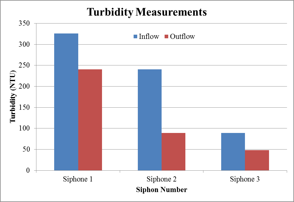 | Figure 7. Turbidity measurements at each siphon sediment basin at 10 hours’ time interval |
5. Conclusions
- Siphon sediment basins have great potential to be used as an effective device to control water turbidity which has not been controlled using the existing concepts provided by the best management practice, BMP. Multi-leveled siphon sediment basins are very effective not only for turbidity control but also in sedimentation and erosion control. The multi-leveled siphon sediment basins design can be tailored to specific sites. The multi-leveled siphon sediment basins could be arranged in parallel, in sequence or combination of parallel and sequential basins. Siphon sediment basin is relative inexpensive turbidity control device that can be field operated and can be easily maintained.
ACKNOWLEDGEMENTS
- This study is conducted in memory of David Lucas, who liked to be called public engineer, and practitioner. He was my student at the age of 81, but I learned from him much more than what he learned from me. He was passionate about public health and safety. He lost his battle with cancer in 2010.