-
Paper Information
- Paper Submission
-
Journal Information
- About This Journal
- Editorial Board
- Current Issue
- Archive
- Author Guidelines
- Contact Us
American Journal of Computational and Applied Mathematics
p-ISSN: 2165-8935 e-ISSN: 2165-8943
2024; 14(2): 25-33
doi:10.5923/j.ajcam.20241402.01
Received: Sep. 26, 2024; Accepted: Oct. 28, 2024; Published: Nov. 12, 2024

Investigation of Vibration Damping Peculiarities in a Nonlinear Dynamical System of One Degree of Freedom
 Abstract
 Reference
 Full-Text PDF
 Full-text HTML
Mečislovas Mariūnas
Department of Biomechanical Engineering, Vilnius Gediminas Technical University, Vilnius LT, Lithuania
Correspondence to: Mečislovas Mariūnas, Department of Biomechanical Engineering, Vilnius Gediminas Technical University, Vilnius LT, Lithuania.
| Email: |  |
Copyright © 2024 The Author(s). Published by Scientific & Academic Publishing.
This work is licensed under the Creative Commons Attribution International License (CC BY).
http://creativecommons.org/licenses/by/4.0/

Based on the resonant and parametric frequencies of the nonlinear dynamic system and the peculiarities of vibration damping in them, a new method is developed that allows to create their linear dynamic models with sufficient accuracy and to determine their stable operating modes and low level of vibrations in them. The latter method is based on a system of four linear differential equations, in which each equation is supplemented with the modulus of the vibration damping force vector. A method for determining the magnitude of the damping force vector modulus of a dynamic system is presented. It is determined that the nonlinear dynamical system has a main coordinate system with a fixed coordinate reference point in the frequency scale. It is shown that in a nonlinear dynamic system, the magnitude of vibration damping is several tens of times higher than the damping of viscous damping forces. The accuracy of the analysis methods presented in the article was verified by numerical calculations.
Keywords: Vibration, Damping, Peculiarities, Excitation forces, Nonlinear, Dynamic system, Quadratic order, Nonlinearities, Resonant, Parametric, Frequencies, One degree of freedom, Mean square value
Cite this paper: Mečislovas Mariūnas, Investigation of Vibration Damping Peculiarities in a Nonlinear Dynamical System of One Degree of Freedom, American Journal of Computational and Applied Mathematics , Vol. 14 No. 2, 2024, pp. 25-33. doi: 10.5923/j.ajcam.20241402.01.
Article Outline
1. Introduction
- Nonlinear systems have a range of behavior not seen in linear vibrating systems. In the absence of exact solutions, the analysis of nonlinear systems is usually undertaken using approximate analysis, numerical simulations and geometrical techniques. Sy - Miin Chow [1] emphasizes that in the absence of exact solutions, the analysis of nonlinear systems is usually performed by applying approximate analysis, numerical simulations, and geometric techniques, when the energy of the vibrating system is dissipated by various mechanisms. Many different models are used to evaluate the damping of dynamic systems in the work of Zu, Zheng and Yiming [2]. When designing nonlinear dynamic systems, it is very important to be able to evaluate the damping properties and possibly change their size during the process. In the analysis of damping in a dynamic system, in many mathematical models the damping forces are related to the movements of the degrees of freedom of the system.The efficiency of the proposed vibration isolation strategy is numerically demonstrated over the original device. Williams et al. [3], for example, solved the problems of vibration damping by developing a nonlinear dynamic vibration damper with properly selected parameters based on the geometry of the overlap truss. Xuechuanan at al. in the book [4] describes various approximate methods: starting from classical asymptotic, finite difference and weighted residual methods, typical methods for solving nonlinear dynamical systems are considered. In addition, new high-performance methods are proposed, such as time-domain collocation and local variation iteration. Vincent et al. [5] showed that the control of nonlinear systems with external excitation can lead to many intriguing and important phenomena, one of the most prominent of which is resonance. In the presence of additional harmonic or stochastic excitation, two exotic forms of resonance can occur: vibrational resonance or stochastic resonance, respectively. Several promising recent technologies are discussed here. These include improving image quality, designing machines and devices that vibrate materials, harvesting energy from various forms of environmental vibrations, and controlling aerodynamic instabilities. In the last work, it is shown that stochastic frequencies can appear in the studied systems. Saunders et al. [6] examines “Freeplay” integrally smooth normal nonlinearities of dynamical systems, which can lead to undesirable and potentially dangerous responses. The latter work numerically investigates the effect of multiple segment parameters during the evolution of the bifurcation diagram along with the induced multiple behavior and different bifurcations. To study the latter phenomena, they use a variety of tools such as harmonic balance, basins of attraction, phase planes, and Poincaré section analysis. Abdelbaki, Paidoussis and Mirsa [7], for example, a full nonlinear model is developed for the dynamics of a hanging tabular cantilever. It is a nonlinear equation of motion obtained via Hamilton’s principle to third-order accuracy. Peng, Lang and Billings [8] studied the vibration frequencies of nonlinear dynamic systems. They showed that, in addition to the vibrations generated by the excitation frequency of the system, vibrations of certain frequencies are additionally excited, which they call resonant frequencies. It is shown that the vibration frequencies of the system are multiples of its excitation frequency. Yang [9] examines the approximate nonlinear response of the system at super/subharmonic resonance. He shows that in many cases, single resonance mode is often observed to be leading as systems enters into super/ sub harmonic resonance. An illustrative example of the discrete mass-spring-damper vibration system is provided for illustration. In the book by Rand [10], nonlinear frequencies of the system are examined by approximate analytical and experimental methods and possibilities to reduce system vibrations are explored. In Zhu [11], a two degree of freedom vibration system with nonlinear damping and nonlinear spring is investigated. The results of the analysis showed that the amplitude and vibration reduction goals can be achieved by properly adjusting the system parameters and evaluating the value of the exciting frequency. Numerical simulations show that the system exhibits periodic motions, quasiperiodic motions and chaotic motions. Xie et al. [12] performed bifurcation tracking based on the harmonic balance method used for tuning nonlinear dynamic systems. Narayanan and Sekar [13] used a numerical-analytical method for the analysis of a nonlinear dynamic system. Yu [14] considered an efficient computational method for the vibrational responses of piecewise-linear dynamic systems with multiple degrees of freedom and an arbitrary number of gap-actuated springs. At each time step an auxiliary displacment vector, complimentary to the contact force vector is introduced. With the help of a simple tranforrmation the vibration is reduced to a standard linear can be obtained. Eliot et al. [15] showed that the energy dissipation mechanism in mechanical systems is often nonlinear. Even though there may be other forms of nonlinearity in the dynamics, nonlinear damping is the dominant source of nonlinearity in a number of practical systems. The analysis of such systems is simplified. For simplicity, it is assumed that the system is stable and that the nonlinear damping force depends on the nth power of the velocity. For sinusoidal excitation, it is shown that the response is often also almost sinusoidal, and methods for calculating the amplitude are described based on the harmonic balance method. In general, iterative methods need to be used to calculate the equivalent linear damper. However, all the methods mentioned above are approximate. When the mathematical models of the linear dynamic system, which change the nonlinear system models, are created, the resonant and parametric vibration frequencies of the nonlinear dynamic system are not properly evaluated. Mariūnas [16-18] studied the vibrations of nonlinear dynamic systems with one and two degrees of freedom, determined the frequencies of resonant and parametric vibrations and a model of a linear dynamic system based on them is created. In recent works, it has been determined that some resonant frequencies may coincide, but cannot be a multiple of the system's excitation frequency. However, it does not fully explain the physics of vibration damping and does not indicate a method to evaluate the way of vibration damping when the mathematical model of a nonlinear system is replaced by a model of a linear dynamic system. Thus, the aim of the work is to analyze the vibrations of one degree of freedom nonlinear dynamic systems, depending on the frequency of the excitation force and its magnitude, to determine (find out) the peculiarities of vibration damping in a nonlinear system and show ways to determine vibration damping in a nonlinear dynamics system. To find out the nonlinear dynamic peculiarities of system vibration damping, especially their dependence on the system excitation frequency, and to create a method that would allow to approximately determine the magnitude of vibration damping of a linear dynamic system changing the model of a nonlinear dynamic system.
2. A Study of Vibration Damping Peculiarities of a Nonlinear Dynamic System of One Degree of Freedom
- This article is basically a continuation of the paper by Mariunas [18]. The work examines the peculiarities of vibration damping of nonlinear dynamic systems, which were not discussed in the latter work. In recent works, it has been shown that the excitation force excites a wide range of vibration frequencies in a nonlinear dynamic system. However, the regularities of vibration generation in linear dynamic systems do not allow to explaining the ongoing phenomenon in a nonlinear dynamic system during the generation and damping of vibrations. Let us study a second-order nonlinear dynamical system of one degree of freedom, the parameters of which are: M = 5.0 kg; k = 100000
 ;
;  = 100000 N;
  n = 2. The resonant frequencies of the subsystems of the latter dynamical system are:
  = 12.99Hz;
  = 18.39Hz;
  = 22.52Hz;
  = 31.85Hz and the resonant frequencies of the main (overall) system are:
 (see [17]). The results of the nonlinear dynamic response of the system to different excitation frequencies of the system
  when
when  and 14Hz are shown in Figure 1. It can be seen that the phase-space diagrams and the vector diagrams in Figure 1a, b and c are different, although in the vibration frequency bands Figure 1d and e, when
  and
and  the order of frequency variation is the same
  It means:
  and
and 
 . Thus, when the dynamic system is excited at frequencies
  and
and  its vibration frequencies change according to the same law, but the rotation angles of the vectors
  and
and  in the coordinate system
  will be different size. For example, it can be seen from Figure 1 that when the dynamic system will be excited at a frequency of
  then the vector
  will rotate at an angle of
  when system will be excited at
  then the vector
  will rotate by angle
  whose magnitude is
  and when the system will be excited
  then the vector
  will rotate by an angle
  the magnitude of which will be
  . The vectors
  and
and  in the above example will also rotate by different angles (see (1)). The nonlinear dynamic system itself performs the transformation of the origin reference point of coordinates for each excitation frequency
  into the reference point of the dynamic system in the frequency scale as follows:
 | (1) |
 is the selected size of the rotation angle of the force vector
  in the global (main) coordinate system and
  is the fundamental lowest frequency in the base reference system that corresponds to the origin of the coordinates;
  is the real size of the rotation angles of the force vectors
  and
and  in the global coordination system. There are also different phase-space diagrams for different excitation frequencies in Figure 1b and c. Figure 1a graphically shows how the phase-space diagrams are formed when the dynamic system is excited at
  Active forces are marked in red, green and blue, and their representative of forces are marked in purple. It can be seen from Figure 1 that when the rotation angle
  of the vector
  is small, then the magnitude of the representative of the acting forces is also small, i.e. it is close to zero. When increasing the size of the angle of rotation
  the representative of the forces increases for a certain time, and when the value of the angle
  approaches the value
  then the size of the representative of the forces does not approach zero, i.e. as shown in Figure 1c. This shows that the nonlinear dynamic system uses the same reference frame in the frequency scale with the same reference point as when it is excited at 10Hz. Phase-space diagrams are drawn with the same reference point on the frequency scale and when the nonlinear dynamic system is excited at other frequencies. Thus, the nonlinear dynamical system uses the same main coordinate system and the same reference point in the frequency scale for all excitation frequencies of the system. The latter main (or basic) reference system is (defined) based on the resonant frequency
  of the nonlinear dynamic system (in the case under consideration, approximately 20Hz) and its subharmonic frequency
  generated by the peculiarities of the force relations of the system and the resonance frequency
  (in the case of the study, approximately 30Hz), which is generated by the characteristics of the stiffness connection. In addition, the subharmonic frequency
  in this case coincides with the excitation frequency of the system, and the harmonics of the excitation frequency, which are parametric excitation frequencies, coincide with the resonance frequencies
  and
and  , i.e. coincides with the fundamental resonant frequencies of the system.
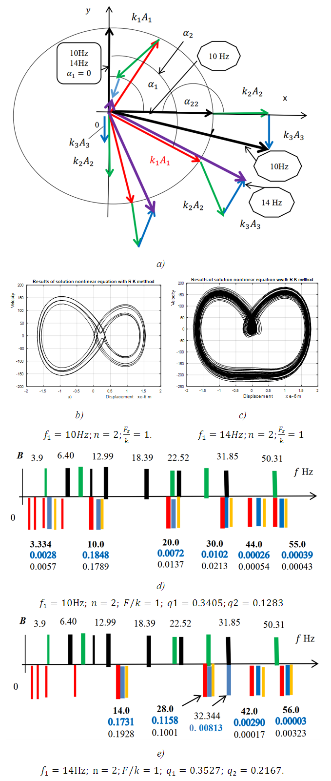 | Figure 1. Plans of the acting force vectors at the points of the characteristic diagrams and frequency bands of the spatial oscillation spectral density when the nonlinear dynamical systems are excited at different frequencies where  is displacement force vector of is displacement force vector of  is displacement force vector of is displacement force vector of  is velocity force vector of is velocity force vector of  is velocity force vector of is velocity force vector of  is the projection of the vector is the projection of the vector  on the coordinate axis 0x; on the coordinate axis 0x;  is the projection of the vector is the projection of the vector  on the coordinate axis 0x; on the coordinate axis 0x;  is the projection of the vector is the projection of the vector  on the coordinate axis 0y; c is coefficient of damping on the coordinate axis 0y; c is coefficient of damping |
 (Figure 1d and e), the resonant frequencies of the dynamic system (green and black colors, that is not shaded in the overall picture, harmonic and subharmonic frequencies are not shown) are placed, below them there are the frequencies of parametric vibrations (thick vertical red lines), their subharmonics (red vertical thin lines) and the vibration frequencies and their amplitudes of the dynamic system (thick vertical blue lines). The vibration amplitudes calculated by the method under consideration are marked in orange with vertical lines. From the results in Figure 1, it can be seen that the vibration amplitude values determined by the developed method and the Runge-Kutta method differ by approximately 15-20 percent, and the vibration frequency spectrum with significant vibration amplitudes completely coincide. The larger difference in amplitudes is at higher frequencies. However, their vibration amplitudes are significantly smaller than the amplitudes of the excitation frequency. It is noticed that there are parametric frequency subharmonics in the nonlinear dynamic system (see Figure1d and e).In order to determine the peculiarities of vibration damping in a nonlinear dynamic system, let's examine the forces acting on it and their relationship with the excitation frequency of the system. From the vector plan of the acting forces in Figure 1, when
  and the rotation angle of the vector
  is equal to
  the following dependence can be written:
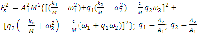 | (2) |
 | (3) |

 and
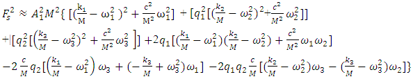
and  generated by the relationship peculiarities of the nonlinear dynamic system. The remaining members of the last equation evaluate the effect of the mutual influence of the above mentioned forces on the system's dynamic stiffness and vibration damping and the frictional forces generated by the viscous damping forces.Thus, if we remove the first term marked with square brackets from equation (3), we get additional stiffness and damping created by the nonlinear dynamic system to damp the vibrations in it. Denoting it as a new variable
  we have the following expression:
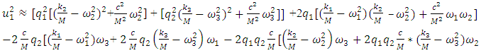 | (4) |
 is the module squared of the vibration additional damping vector (or dynamic stiffness and damping) generated by the nonlinear dynamic system. We assume that in linear system (in the system under consideration) when the magnitude of the vibration amplitude
  changes, then the dynamic parameters of the system:
 values are constant. Equation (4) is used to determine the square of the total vibration damping vector module according to one coordinate axis 0x. In the investigated dynamic system in Figure 1, the stiffness springs are connected in parallel. And in the mathematical model (5) of the linear dynamic system, they are connected in series. Therefore, the differences in the mathematical models of the latter dynamical systems will be evaluated by an additional modulus of the force vector
  . Thus, after supplementing the linear mathematical model Mariūnas [16] with an additional vector module
  according to each displacement coordinate axis, we will get a new system of differential equations:
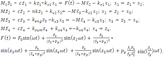 | (5) |
 , and when it is higher then the maximum resonant frequency then
  . However, there are still unknown values of the vector modulus
  when
when  . Therefore, it is assumed that in a linear dynamic system in which the stiffness springs are connected in series (5), the size of the vibration damping force vector module
  can be calculated as the average of the squares of the vector modules of the forces acting in the dynamic system, and
  - as the average of the three vector modules:
 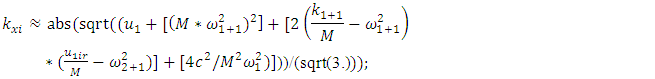 | (6) |
 | (7) |
 | (8) |
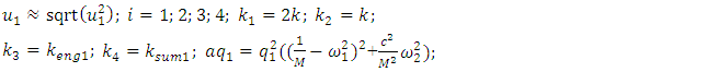
 | (9) |
 | (10) |
 vector module can be considered as the average of the force modules acting in the dynamic system was justified. They also show that
  is a constant value in the nonlinear dynamic system for the value of the corresponding excitation frequency
  according to each coordinate axis. Since there are seven modules of vector forces in equation (7) (see (4)), their sum must be divided by seven. The variable part of equation (6) has three terms for each coordinate axis of the dynamic system. They are marked with square brackets (see (6)). Since there are four equations in the system of equations (5), that is, four coordinates, so when creating the fourth equation for determining the size of the vibration damping vector module
  the value of the
  parameter in equation (6) will be higher than in the system of equations (5). This means that such stiffness and velocities will not exist in the considered system. The result of the study is that the magnitude of the additional force vector module of the fourth equation of vibration damping has a very small influence on the final result. Therefore, when
  then the values of stiffness and velocities corresponding to the value of the parameter i = 4 were taken in the research, this means that
  . In this way, during the study it was determined that when the system is excited at a frequency of
  then the size of the vector module
  is sufficiently accurately determined as the average of the vector modules of the forces acting on the nonlinear dynamic system. However, there are still undetermined values of
  and
and  parameters. Since there are two unknowns
  and
and  , it is necessary to form two equations. So, in the first step, we transform (2) into the following form:
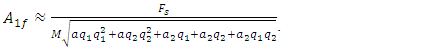 | (11) |
 and
and  :
: | (12) |
 | (13) |
 | (14) |
 | (15) |
 the maximum value of which is the amplitude
  . Evaluating the difference in stiffness of springs connected in parallel and in series with the help of coefficient
  (14) and equating the latter value of
  with the value of
  (11), we will get the first equation of system equations (12). The second equation of the system of equations (12) is formed by comparing the linear dynamic kinetic and potential energy expressions of the system, in which the springs are connected in series:
 | (16) |
 is also suitable for other cases, that is, when the nonlinear dynamic system is excited at
  Although in a nonlinear dynamic system, when it is excited at 10 and 14Hz, the vibration frequencies varies according to the same low
  but in a more detailed overview we will notice the following main differences and peculiarities:– when the dynamic system is excited at frequencies
  and the conditions that
  and
and  are satisfied, then between the vector forces
  and
and  there is the same phase size, that is:
 since the initial point in the phase - space diagram is at the coordinate origin, it means, when
  and
and  (see Figure 1). And that condition can be fulfilled only in the case when
  , that is, when the amplitudes of
  and
and  will be in opposite phase to the amplitude of
  or the vectors
  and
and  will be collinear and opposite in direction to the vector
  ;– if the excitation frequency
  of the nonlinear dynamic system coincides or is approximately equal to the resonant frequency of the first subharmonic of the main resonant frequencies
  of the system, then the vibration of the first harmonic of the parametric vibrations of the dynamic system will be in opposite phase for excitation frequency. In both considered cases, the vibration frequencies of the system will change according to the same law
 but when the system is excited at
  subharmonic frequency then the following inequality
 will be satisfied, and when the system is excited at
  subharmonic frequency then such inequality
  , but
, but  ; – it is determined that when the dynamic system is in the excitation frequency range 2 - 60Hz, that is, more than three times lower than the system's lowest resonant frequency and higher than its highest resonant frequency in the frequency interval, then in all cases in the phase - space diagrams, when t = 0, then
  and
and  . In this way, from the peculiarities of the nonlinear dynamic system presented above, it can be seen that changing the frequency of the excitation system changes some of its peculiarities or its physical characteristics, which can have a significant impact on the dynamic and mathematical models of the nonlinear dynamic system. So, based on the peculiarities of the nonlinear system listed above, it is clarified that when it is excited at frequencies that are in the range of subharmonic frequencies of the main resonant frequencies of the system, i.e. from
  to
to  then the frequencies of the vibration amplitudes will change according to this rule
  When the dynamic system is excited
  approximately within these limits, then the frequencies of vibration amplitudes will change according to the rule
 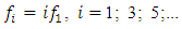 Moreover, in the latter case, the vibration amplitude
  and
and  because its size is many times smaller than
  . Therefore, based on the clarified features of the nonlinear dynamic system, the mathematical model examined above is checked to see if it is suitable when the system is excited at a frequency of
  From the forces vector diagram in Figure 1a, when it is excited with the frequency
  it can be seen that the values of the latter vector projections in the coordinate axes 0x and 0y will be different than in the case when the dynamic system is excited with the frequency
  This means that for each excitation frequency
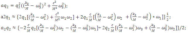
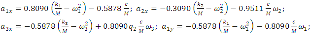
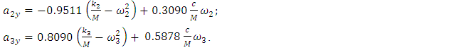
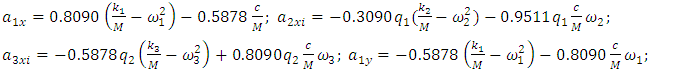
  of the dynamic system, the mathematical model of the latter system needs to be refined.So based on (2); (3) and (4), when evaluating the projections of the acting vectors onto the coordinate axes (see Figure 1a), the following dependence is obtained:
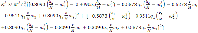 | (17) |
 | (18) |
 in expression (18) is quite complex and would take up a lot of space when expanding it. The value of the last term of the bases of equations (3) and (18) can be determined as follows:
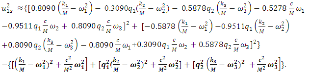 | (19) |
 then we will determine the modulus of the sum vector of the forces acting in the nonlinear dynamic system as follows:
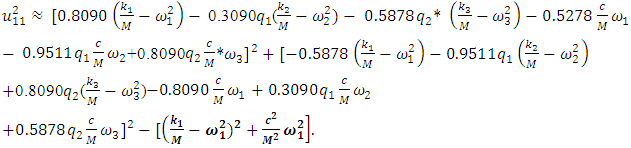 | (20) |
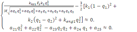
 in the considered case as follows:
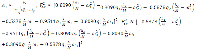 | (21) |
 and
and  . In fact, in the system of equations (12), only the first equation must change, because only the dependence of determining the size of
  changes (see (15) and (21)).
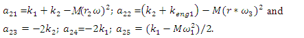
 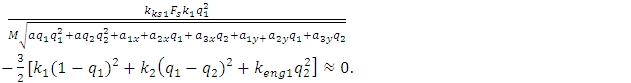 | (22) |
 | (23) |
 | (24) |
 and
and  in the case when the excitation frequency is
 . Then we will determine the magnitude of the vibration damping vector module when the dynamic system is excited at
  as follows:
 | (25) |
 | (26) |
 | (27) |
 | (28) |
 | (29) |
 (see (26)) is also constant according to each coordinate of the movement of the dynamic system. It is necessary to pay attention to the fact that only by summarizing the results of the above researches, the latter method has been developed that is suitable for all excitation frequencies of the dynamic system and does not require complex transformations in determining the magnitude of the additional vibration damping force vector module. So, the research results show that when the excitation frequency
  changes, the mathematical model of the system also changes. The frequency band of the spectral density determined by the considered method when the dynamic system is acted at the frequency
  is shown in Figure 1. Without changing the dynamic and mathematical models when the system is activated at
  the latter model was applied to the case when the system is excited at 6Hz. The calculation results when
  are shown in Figure 2.
 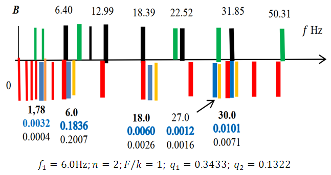 | Figure 2. Spatial vibration spectral density frequency bands in the B0f plane when the dynamic system is excited at  |
 was chosen so that in the case of parametric vibration the frequency changes
  when i changes according to the rule i =1; 3; 5…, while when
  and
and  changes according to the rule 1. 2; 3; 4... However, in other cases, when
  it is necessary to create a new model corresponding to the excitation frequency of the dynamic system. In this way, it is determined that when the dynamic system is excited at a frequency of
  then there are analogous damping peculiarities. Except for the fact that the magnitudes of the rotation angles of the vectors
 and
and  will be different than in the examples discussed above.Using the mathematical model method based on the system of linear differential equations, the spectral densities of the vibrations of the nonlinear dynamic system are calculated when the system is excited at
  and
and  the results of which are shown in Figure 3. From the results of which it can be seen that when a nonlinear dynamic system is excited with frequencies higher than its maximum resonant frequencies, then low-frequency vibrations are excited in the system, which are multiples of the excitation frequencies and they approximately coincide with the frequencies of the subharmonics of the resonant frequencies. In the case when the work mode of the latter case does not suit you and you cannot change the exciting frequency work mode, then it is necessary to change the values of the main parameters of the nonlinear dynamic system, which would allow you to ensure safe and stable work of the designed system.
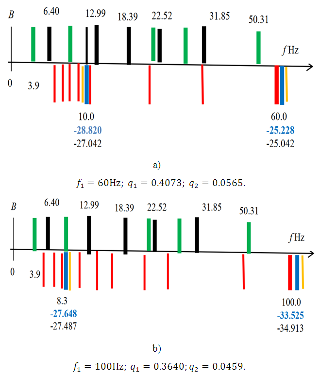 | Figure 3. Spatial vibration spectral density frequency bands in the B0f plane when the dynamic system is excited by different excitation frequencies and  |
 | (30) |
3. Conclusions
- In this work, the peculiarities (process) of vibration damping in a nonlinear dynamic system are analyzed, and based on the research results, a new method of a system of linear differential equations is developed, suitable for studying the vibration dynamics of a nonlinear dynamic system with one degree of freedom. A method for determining the magnitude of the damping force vector modulus of a dynamic system is presented.The analytical results indicate that:1. Based on the resonant and parametric frequencies of the nonlinear dynamic system and the peculiarities of vibration damping in them, a new method has been developed, which allows creating their linear dynamic models with sufficient accuracy and determining their stable operating modes and low level of vibrations in them.2. The nonlinear dynamic system has a main coordinate system, the coordinates of the reference point on the frequency scale do not change with the excitation frequency.3. When the excitation frequency of the nonlinear dynamic system changes, its mathematical model also changes.4. The magnitude of the additional damping force vector module in a nonlinear dynamic system is determined as the mean square value of the force modules generated by peculiarities in it.The results of numerical calculations1. It was determined that the results of the calculation of the mathematical model of the created linear dynamic system differ by 15-20 percent from the results calculated by the Runge-Kutta methods.2. In a nonlinear dynamic system, the vibration damping magnitude of forces generated with the help of stiffness, forces and energy connection peculiarities is several tens of times higher than the damping of viscous damping forces. 3. The developed methods evaluates the nonlinear dynamic system vibration damping process with sufficient accuracy and can be used in the development of new systems.