-
Paper Information
- Paper Submission
-
Journal Information
- About This Journal
- Editorial Board
- Current Issue
- Archive
- Author Guidelines
- Contact Us
American Journal of Computational and Applied Mathematics
p-ISSN: 2165-8935 e-ISSN: 2165-8943
2017; 7(2): 51-57
doi:10.5923/j.ajcam.20170702.04

N-dimensional Rotation Matrix Generation Algorithm
 Abstract
 Reference
 Full-Text PDF
 Full-text HTML
Ognyan Ivanov Zhelezov
Dep. of Development, Firm Data Consulting, Sofia, Bulgaria
Correspondence to: Ognyan Ivanov Zhelezov, Dep. of Development, Firm Data Consulting, Sofia, Bulgaria.
| Email: |  |
Copyright © 2017 Scientific & Academic Publishing. All Rights Reserved.
This work is licensed under the Creative Commons Attribution International License (CC BY).
http://creativecommons.org/licenses/by/4.0/

This article presents a new algorithm for generation of N-dimensional rotation matrix M, which rotates given N-dimensional vector X to the direction of given vector Y which has the same dimension. Algorithm, named N-dimensional Rotation Matrix Generation Algorithm (NRMG) includes rotation of given vectors X and Y to the direction of coordinate axis x1 using two-dimensional rotations. Matrix M is obtained as multiplication of matrix MX and inverse of matrix MY, which rotates given vectors to the direction of axis x1. Also examined is the possibility to perform parallel calculations of two-dimensional rotations.
Keywords: Mathematics of computing, Mathematical analysis, Numerical analysis, Computations on matrices
Cite this paper: Ognyan Ivanov Zhelezov, N-dimensional Rotation Matrix Generation Algorithm, American Journal of Computational and Applied Mathematics , Vol. 7 No. 2, 2017, pp. 51-57. doi: 10.5923/j.ajcam.20170702.04.
Article Outline
1. Introduction
- High-dimensional spaces frequently occur in mathematics and the sciences, in example N-dimensional feature space, which presents input signals of neural network or collection of N-dimensional parameters for multidimensional data analysis. Rotation is one of rigid transformations in geometrical space, which preserves length of vectors and can be presented using matrix operation like Y = M.X, where X and Y are input and output vector respectively, and M is rotation matrix. This article proposes an N-dimensional rotation matrix generation algorithm for given input and output vector.
2. Definition of the Task
- Let's say that we have two N-dimensional vectors X and Y, having the same dimension, X, Y ∈ RN. We want to obtain a rotation matrix M that satisfies the equation.
 | (1) |
 has the same norm as X and the same direction as Y, i.e.
  and
and  One of possibilities to generate rotation matrix M includes the following sequence of operations:1) Obtain two orthogonal vectors in the plane, in which lies the two given vectors using Gramm-Schmidt procedure [2, 3, 16].2) Enlarge this 2-dimensional basis to N- dimensional basis B2, in which given vectors X, Y are transformed to
  and
and  .3) Create matrix of Givens rotation G(1, 2, θ) for RN, which makes rotation of vector
  in
in  -plane to the direction of vector
  4) Obtaining rotation matrix M as
 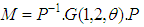 | (2) |
 there exists an orthogonal symmetric matrix P such that
  where
where 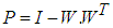 and
and 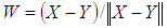 . Matrix P is matrix of reflection (not a rotation) because det P = -1, (which gives the name to method) that’s why to obtain matrix of rotation M, for which det M = 1, have to be performed two subsequent reflections. Matrix of rotation can be obtained as multiplication of two matrix of reflection P1 and P2 as M = P1.P2.This article presents a new algorithm for generation of N-dimensional rotation matrix, which rotates given vector X to the direction of given vector Y. Algorithm, named N-dimensional Rotation Matrix Generation Algorithm (NRMG) includes the following sequence of operations:1) Obtaining rotation matrix MX, which rotates given vector X to the direction of axis
  2) Obtaining rotation matrix MY, which rotates given vector Y to the direction of axis
  3) Obtaining rotation matrix M as multiplication of MX by inverse matrix of MY given as
 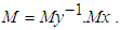 Below this three operations will be described subsequently
3. Rotation of Given Vector X to the Direction of Axis x1
- Rotation of given vector X to the direction of one of coordinate axes (e.g. axis
 ) can be performed by subsequent multiplications by Givens matrices [1] as follow:
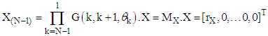 | (3) |
 | (4) |
 to
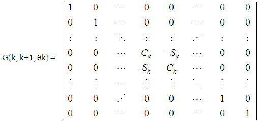
to  . This multiplication can be presented as multiplication of coordinates by sub matrix A(k, k+1, θk) as follows:
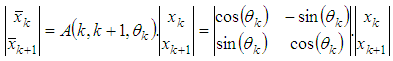 | (5) |
 (to
(to  ), schema of multiplication by Givens matrix G(k, k+1, θk) can be presented as operator for two-dimensional rotation as follows:
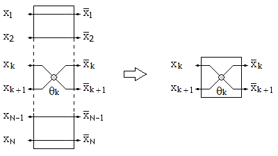 | Figure 1. Schema of two-dimensional rotation, performed by Givens matrix G(k, k+1, θk) |
 It is easy to find that equation
  and equations (5) are satisfied simultaneously when
  and
and  are calculated using formulas:
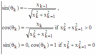 | (6) |
 as follows:
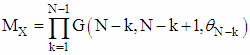 | (7) |
 and
and  are calculated using formulas (6). Calculation of angles of two-dimensional rotations
 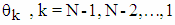 really is not needed. If
 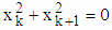 then corresponding Givens matrix is equal to Identity matrix G(k, k+1, θk) = I – no rotation.Schema for rotation of vector X to the direction of axis
  using two-dimensional rotations can be presented as follows:
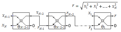 | Figure 2. Schema for rotation of vector X to the direction of axis  |
 to the direction of axis
  k=1,2,…N-1. This two-dimensional rotation is the base operation of proposed algorithm.
 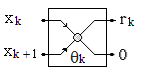 | Figure 3. Block of base operation - rotation of two-dimensional vector  to the direction of axis to the direction of axis  |
 needs execution of N-1 subsequent base operations. Thus if one base operation has execution time Tb, then rotation of given N-dimensional vector X to the direction of axis
  will take execution time (N-1).Tb. As it is described below, this time can be reduced using parallel execution of base operations.
4. Description of NRMG Algorithm
- NRMG algorithm for generation of N-dimensional rotation matrix M, which rotates given vector X to the direction of given vector Y consist the following operations:1) Obtaining rotation matrix MX, which rotates given vector X to the direction of axis
 2) Obtaining rotation matrix MY, which rotates given vector Y to the direction of axis
  3) Obtaining rotation matrix M, which rotates given vector X to the direction of given vector Y as multiplication of matrix MX and inverse matrix of MY, as follows:
 | (8) |
 , which will have norm of vector X, but direction of vector Y.Time complexity of proposed algorithm depends of algorithm, used for calculation of coefficients
  and
and  of two-dimensional base operations. This calculation depends of practical realization and is not a subject of this article.NRMG algorithm can be used for different reversible calculations. An example that uses NRMG algorithm for transformation of images appears below (6).
5. Increasing Performance Using Parallel Execution of Two-Dimensional Rotations
- Parallel execution of two-dimensional rotations (base operations of algorithm) is one way to increase calculation performance. This possibility is proposed in [7, 8] in relation of matrix decomposition. As this parallelism gives significant decrease of subsequent calculations, below will be presented one realization of this approach for proposed algorithm without pretensions of novelty.Let’s have N-dimensional vector
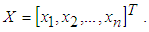 Vector X can be presented as a sum of two vectors X1 and X2, every one of which has half coordinates of value zero and half coordinates, that have the same values as the coordinates of given vector X, as follows:
 | (9) |
 by multiplication with matrix of rotation M will give resultant vector X12(N/2) which is the sum of rotated to the direction of axis
  vectors X1 and X2 as follows:
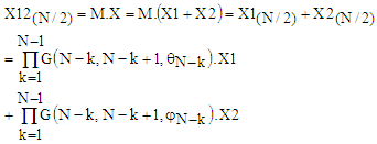 | (10) |
 | (11) |
 . Vector X(N/2) to the direction of axis
  can be obtained by only one two-dimensional rotation of vector X12(N/2) in this coordinate plane as follows:
 | (12) |
 As it can be seen from (8)÷(10) and from schema on Fig. 4, after one division of given vector X the number of subsequent base operations is decreased to N/2 regardless that the number of base operations remain the same – N-1. It is easy to find that separation of given vector X to more then two parts will give more decreasing of subsequent base operations.
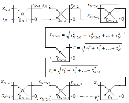 | Figure 4. Schema for rotation of vector X, separated into two parts, to the direction of axis  |
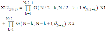
 (set of all natural numbers) then the number of subsequent rotations, needed to obtain vector with only one non-zero element, is equal to log2N.
 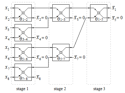 | Figure 5. Schema for accelerated rotation of 8-dimensional vector to the direction of axis  |
 will look as on figure aboveIt is important to note the following:1) Accelerated rotation (AR) of given vector to the direction of axis
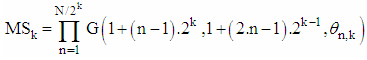
  can be applied not only for vectors, that have dimension N=2P, P∈N, but for every one vector with dimension greater then 2. In example if N=7 then difference between schema of AR and those, given above, will be only this, that in first stage will miss the last base operation and x7 will go straight to base operation on second stage. 2) The number NR of stages (in which parallel execution of base operations of AR have to be performed) is equal to ⌈log2N⌉ whereas number of all base operations is N-1 – the same as when all rotations are subsequent.3) AR really increases calculation performance in case of parallel execution of base operations in stages. If base operations in stages are executed consecutively, the only advantage of AR is decreasing of accumulation of calculation errors (due to rounding e.g). For high dimensional vectors AR proposes significant decreasing of subsequently executed base operations. In example if dimension of vectors is N=1024, the number of subsequently executed base operations is 1024-1, whereas AR algorithm uses number of stages (which defines the number of subsequent base operations) NStages = log21024 = 10. It is important to note, that rotation is reversible linear operation, which mean that AR is reversible linear operation too. Reversibility of rotation, in particularly AR, is the “key stone” of proposed NRMG algorithm.When AR is used, rotation matrix MX and MY can be presented as a multiplication of matrices MS1, MS2, … MSNR, which correspond to the stages of rotation, shown in Fig. 5. In example for vector with dimension N=8 matrices of stages MS3.MS2.MS1 will look as in Fig. 6. where C1,1, S1,1, C1,2, S1,2, C1,3, S1,3, C2,1, S2,1,C2,2, S2,2, C3,1, S1,3 are denotation of
  and
and  index i is the number of stage, and j is the number of base operation.
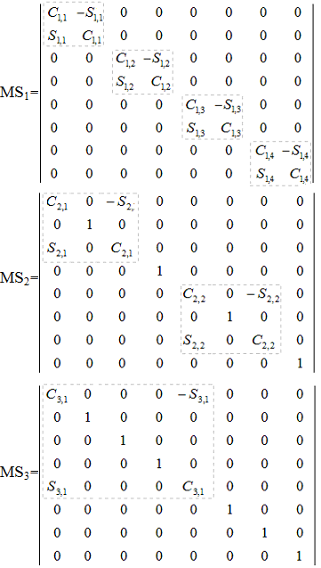 | Figure 6. Matrices of stages for AR of 8-dimensional vector |
 | (13) |
6. Reversible Transformation of Images Using NRMG Algorithm
- Down we will give one example of using NRMG algorithm for reversible image transformation.Let’s have two monochrome raster images I1 and I2 which have the same number of pixels N. As it is known [14], raster images are presented as dot matrix data structure, so the two given images can be presented as two N-dimensional vectors X and Y, every element of which presents brightness of one of pixels. Using NMRG algorithm can be obtained rotation matrix M, which rotates vector X to the direction of vector Y. Since rotation do not change the norm of the vector, resultant vector
 will have the same norm as X. As a result, rotation will transform image I1 to one presentation of image I2, brightness of every one pixel of which is equal to the brightness of corresponding pixel of image I2, scaled with coefficient
  . If X and Y have the same norm, vectors
  and Y will be identical.
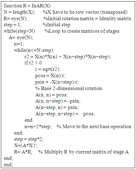 | Example 1. Code of Matlab function for accelerated rotation of vector X to the direction of axis x1. Function returns matrix of rotation MX |
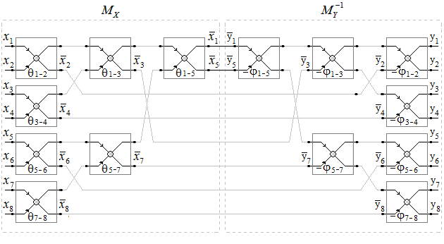 | Figure 7. Schema for rotation of 8-dimensional vector X to the direction of vector Y using NRMG algorithm and AR |
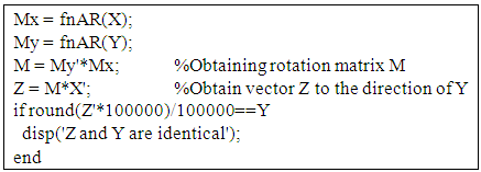 | Example 2. Code of Matlab, which creates matrix of rotation using fnAR function |
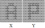 | Figure 8. Test images |
7. Conclusions
- In this article, we presents a new algorithm for generation of N-dimensional rotation matrix M, which rotates given N-dimensional vector X to the direction of given vector Y which has the same dimension. Also examined is the possibility to perform parallel calculation of base operations - two-dimensional rotations. Algorithm can be used for different reversible calculations. It is included one example of image transformation that uses NRMG algorithm.Proposed NRMG algorithm proves that1) Every one matrix of rotation M, which rotates given vector X to the direction of given vector Y can be presented as
 where MX rotates vector X to the direction of one of coordinate axes (e.g. axis x1) and MY rotates vector Y to the direction of the same coordinate axis.2) Every one rotation of N-dimensional vector can be performed by 2(N-1) two-dimensional rotations in N-1 coordinate planes.As an advantage of NRMG algorithm to known solutions, (shortly described in p. 2), can be pointed a possibility to realise it as Discrete Linear System, elements in which performs base operations. This possibility is a result of the locality of data, used for base operations and independence of base operations inside one stage of rotation.