-
Paper Information
- Previous Paper
- Paper Submission
-
Journal Information
- About This Journal
- Editorial Board
- Current Issue
- Archive
- Author Guidelines
- Contact Us
American Journal of Computational and Applied Mathematics
p-ISSN: 2165-8935 e-ISSN: 2165-8943
2014; 4(5): 167-185
doi:10.5923/j.ajcam.20140405.03
Deflection Control of SMA-actuated Beam-like Structures in Nonlinear Large Deformation Mode
 Abstract
 Reference
 Full-Text PDF
 Full-text HTML
Mohammad Reza Zakerzadeh1, Hassan Sayyaadi2
1School of Mechanical Engineering, College of Engineering, University of Tehran, Tehran, Iran
2School of Mechanical Engineering, Sharif University of Technology, Tehran, Iran
Correspondence to: Mohammad Reza Zakerzadeh, School of Mechanical Engineering, College of Engineering, University of Tehran, Tehran, Iran.
| Email: |  |
Copyright © 2014 Scientific & Academic Publishing. All Rights Reserved.
Flexible structures actuated by Shape Memory Alloy (SMA) actuators have been taken attentions in various applications of many scientific/technologic fields recently, like morphing wings. However, position control of these flexible structures is a difficult task especially in the large deformation mode due to some nonlinearity in behaviors, hysteresis effects, etc. First, Shape Memory Alloy (SMA) actuators behave with sever nonlinear dynamics while performing saturated hysteresis behavior during their forward and reverse transformations. Second, flexible structure behaves nonlinear in large deflection mode and as a result becomes more sensitive to the actuator applied force. As a result of these interactions between SMA and flexible structure, effective utilization of SMA-actuated flexible structure is a very recent challenge topic. In order to overcome to these two challenging points, in this paper, hysteresis nonlinearity of SMA-actuated flexible structure is modeled by the generalized Prandtl–Ishlinskii model. Consequently, a feedforward–feedback controller is used to control the tip deflection of the beam-like SMA-actuated structure. The feedforward part of the controller is based on the inverse generalized Prandtl–Ishlinskii model while a conventional proportional–integral feedback controller is added to the feedforward control system to increase the accuracy together with decreasing the steady state error in position control process. Besides, in order to eliminate the second aforementioned challenging point of nonlinear behavior in large deflection of flexible structure, another auxiliary SMA actuator is attached to the structure. It is experimentally shown that, in comparison to the case that only one SMA actuator is attached to the structure, the proposed controller in the new architecture, including two SMA actuators, not only increases the accuracy of the position control in small deflection mode, but also the position control process can be performed with great precision in large deformation behavior of the structure. It means simply that using two SMA actuators in the control architecture proposed here performs accurate tip positioning of flexible beam structure in both small and large deflection modes.
Keywords: Shape Memory Alloy Actuator, Position Control, Smart Structure, Large Deformation Mode
Cite this paper: Mohammad Reza Zakerzadeh, Hassan Sayyaadi, Deflection Control of SMA-actuated Beam-like Structures in Nonlinear Large Deformation Mode, American Journal of Computational and Applied Mathematics , Vol. 4 No. 5, 2014, pp. 167-185. doi: 10.5923/j.ajcam.20140405.03.
Article Outline
1. Introduction
- In smart materials, shape memory alloys (SMAs) have been receiving considerable attention because of their abilities to develop extremely large recoverable strains, as well as great forces. As a result, SMA actuators are applied in a wide variety of technological fields such as aeronautics, medicine, civil and mechanical engineering [1] consequently. Using these actuators in adaptive and smart structures are another characteristically applications of these SMA materials that have been applied in vibration control as well as shape control such as morphing wing applications [2]. By embedding SMA actuator or bonding it to the surface of the flexible structure, as a result of moment of the actuating force, the structure deforms. Although by increasing the distance between the SMA actuator and the neutral axis of the structure the moment will increases linearly, the flexural stiffness of the structure enhances as a square of this distance [3]. Another problem of using an SMA actuator in embedding form is its heat transfer characteristics. This problem restricts the high-frequency response of the SMA actuator, which is very important in shape control applications where high bandwidth is needed. To overcome the mentioned limitations, SMA actuators are externally attached to the structure. This configuration can be advantageous in several aspects. First, due to large offset distances from the neutral axis of the structure and actuator, more bending moment is produced and as a result achieving large deformation mode of the structure is possible [4]. In addition, the increase in the flexural stiffness of the structure can be neglected and also the heat transfer problems are eliminated. As a result, and especially when getting large deformation mode of the structure is desirable, the externally attached SMA-actuated structure have more attractions with respect to the cases in which SMA actuators are embedded within composite laminate.According to the recent research results by authors [5], though the deflection of the externally attached SMA-actuated structure can be controlled by only one SMA actuator, this brings about some problems. To begin with, achieving the large deflection mode of the structure is difficult and it is only possible when the SMA actuator is attached to the end of the structure. In this case, due to severe sensitivity of the structure to the force applied by the actuator, position control of the tip of the structure is much challenging. Moreover, during SMA phase transformation, small changes in SMA electrical current can increase the actuator stress significantly and as a result the deflection of the structure can be changed significantly. Therefore, controlling of the deflection of a structure by only one externally-attached SMA actuator is a difficult task. To eliminate these problems and in order to have fair controllability in large deflection mode of the structure, it is required to attach two active SMA actuators to the structure. Based on the nonlinear formulation of a flexible beam-like structure actuated by two active SMA wires [5], one of these SMA actuators should be attached to the tip of the structure and another should be attached near the basement of the structure. By this configuration, not only getting large deformation mode of the structure is accessible but also, due to the reported results in the mentioned paper by authors [5] and as it will be shown experimentally here in the following sections, the precise position control of the structure is extensively achievable. In addition, this approach can be generalized to the structure actuated by more than two SMA actuators and thus, in this configuration there is a freedom to control the position of some points on the structure simultaneously, leading to shape control of the structure. Another issue that should not go unattended in position control of these smart structures is the nonlinear saturated hysteresis behavior of SMA actuators during forward and reverse transformations. Experimental results of the studies in the recent years show that if the conventional linear controllers are used for position control of SMA actuators, steady-state errors and limit cycle problems will be observed [6]. However, using nonlinear controllers, in comparison with the linear ones, leads to fast tracking as well as great accuracy in SMA position control. In the first approach of designing such nonlinear controller, called model-based controllers, the controller is designed based on the governing equations of the developed model [7-12]. This group of controllers suffers from the unmolded aspects of SMA actuators and also great attempts are needed to identify the model parameters experimentally [13]. In the other approach, the feedforward nonlinear controller is developed based on an inverse hysteresis model. Since, using this method cannot compensate the hysteresis nonlinearities in the SMA actuators completely and also near the phase transformation regions, the strain of SMA actuators have severe sensitivity to small changes in SMA temperature or applied electrical current, in practice a feedback controller (usually a simple linear one) is also used with the feedforward open loop controller [14]. This strategy can also cancel the disturbance effects. Based on the current research [15], the phenomenological hysteresis models like Preisach model, Krasnosel'skii- Pokrovskii model and Prandtl-Ishlinskii model can model the nonlinear hysteresis behavior of the SMA actuators effectively [16-20] and as a result, using the inverse of such hysteresis models as a feedforward controller, in comparison to the other nonlinear control methods, leads to more accurate results in tracking a command input. It is shown experimentally in [15] that, in comparison to other phenomenological hysteresis models, the generalized Prandtl-Ishlinskii model formulated by Al Janaideh, Rakheja and Su [21] is capable of modeling the saturated asymmetric hysteresis behavior of SMA actuators with more accuracy, especially for minor hysteresis loops that are challenging in position control. This phenomenological hysteresis model has also simple structure, and is analytically invertible and as a result has attracted great attention during recent years in control of smart structures [21-24].Based on the abovementioned challenges in controlling the SMA-actuated structure especially in large deformation mode, this issue is taken into consideration in the current research. In this paper position control of a flexible beam-like structure actuated by two active SMA wires is addressed. Based on the modeling result of current research [5], in order to bend the structure in large deformation mode and also to have fair controllability, one of this SMA actuator is attached to the tip of the beam and the other, as an auxiliary SMA wire, to the middle of structure. The configuration of a flexible smart structure actuated by two active SMA wires is introduced in the first section of this paper. Then the generalized Prandtl-Ishlinskii hysteresis model formulated by Al Janaideh et al. [21] is introduced for modeling the hysteresis behavior between the SMA actuator’s electrical currents and the tip deflection of the structure. Since there are infinite scenarios for heating each of the SMA wire individually and due to single input property of the Prandtl-Ishlinskii hysteresis model, during heating and cooling the SMA wires, the same electrical current is applied to both SMA wires. This strategy also prevents much stress on only one SMA wire during its heating and cooling process and as a result none of the SMA wires are loosen during deflecting the structure [5]. Consequently, on the account of the analytically invertible property of the generalized Prandtl-Ishlinskii model, the formulation of the inverse model is presented for compensating hysteresis behavior between the system inputs (SMA electrical currents) and output (beam tip deflection). An experimental test set-up used for validation of the modeling results as well as tracking control system is presented and some tests are conducted to identify the parameters of the hysteresis model. Excellent agreement between the curves predicted by the generalized Prandtl-Ishlinskii model and the experimentally reported data shows that the model is effective for modeling the hysteresis behavior of the system. Consequently, the inverse of the generalized Prandtl–Ishlinskii model as a feedforward controller is cascaded to the SMA actuators system to compensate its hysteresis. In addition, a conventional proportional–integral feedback controller is added to the feedforward control system to increase the accuracy together with eliminating the steady state error in position control process.Some tracking control experiments for sinusoidal trajectory, with and without minor loop tracking are performed. In these tests the results of two cases are compared, one is a structure with two active SMA wires actuation and the other is a structure without using the auxiliary SMA wire. Experimental results show that, if in addition to the main SMA wire, the auxiliary SMA wire is attached to the beam, the tracking control performance is greatly improved compared to the time when only the main SMA wire is actuating the structure. In addition, in large deflection mode of the beam, that is accessible only by two SMA wire actuations and is a control challenge for the smart structures actuated by SMA wires, it is shown that the position control is performed with the reasonable accuracy.
2. Configuration of the Flexible SMA-actuated Beam-like Structure
- A real smart SMA-actuated structure can be attached to only one actuator or several actuators can be used. But as it is shown in the recent research [5], in order to have the structure in the large deformation mode and also have excellent accuracy in the position control of the structure, externally attaching two SMA wires to the structure is essential. The arrangement of a beam and the two externally-attached SMA wires (SMA wire 1 and SMA wire 2) prior to and after the deformation is schematically shown in Figure 1. It is shown in the stated paper [5] that because of the larger moment of force of the main SMA wire 2 (F2) about the base of the beam, the system is more sensitive to the variation of this force rather than variation in the force of auxiliary SMA wire 1 (F1). It means that having great accuracy in large deflection mode of the structure is much difficult when only SMA wire 2 is used. Also when SMA wire 1 is just attached to the beam, deforming the structure to large deflection mode is impossible. Therefore, in order to have precise position control of the beam in large deflection mode two SMA wires, one with large offset (d2) attached to the tip of the beam and one with small offset (d1) attached near the base of the beam, should be used (i.e. d2>d1 and L2>L1). As stated before, externally attaching these SMA wires not only helps to achieve large deformation mode of the structure, but also heat transfer problems are eliminated consequently. Since most of the SMAs undergo a change in behavior under cycling loading [25], it is assumed that the SMA wires have been initially stabilized and then attached to the beam. Incidentally, before attaching the SMA wires to the beam they are subjected to a tensile stress in order to induce some prestrains in the wires.
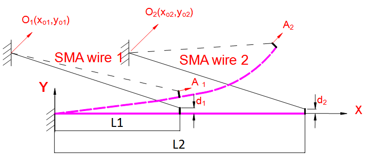 | Figure 1. Schematic illustration of the smart structure with its SMA wires prior and after deformation |
3. Prandtl-Ishlinskii Model
- Prandtl-Ishlinskii model is one of the great operator-based phenomenological models which is used in modeling complex hysteretic nonlinear behavior of smart actuators. The most attractive as well as unique aspect of the Prandtl-Ishlinskii model is that, unlike other phenomenological hysteresis such as Preisach and Krasnoselskii-Pokrovskii models which their inverses are addressed numerically, this model is analytically invertible and as a result can be simply implemented as a feedforward controller in compensating the hysteretic nonlinearity behavior of smart actuator [15].Because of unbounded nature of the classical play operator, the Classical Prandtl-Ishlinskii model, the first from of this model, cannot describe systems with output saturation. In addition, as a result of the symmetric nature of the play operator, applying the classical Prandtl-Ishlinskii model results to significant error when there is an asymmetric in the input-output hysteresis loops, like in shape memory alloy and magnetostrictive actuators [26]. In order to eliminate these shortcomings, some modifications are applied to the Classical Prandtl-Ishlinskii model (see for example [23, 27-30]). Recently, Al Janaideh, Rakheja and Su [26] applied an asymmetric generalized play hysteresis operator to the classical Prandtl-Ishlinskii model in conjunction with density function to characterize asymmetric hysteresis behavior of smart actuators. The proposed generalized operator can be directly applied in conjunction with the Prandtl–Ishlinskii hysteresis model for characterizing symmetric as well as asymmetric hysteretic properties of smart actuators with output saturation.
3.1. Generalized Prandtl-Ishlinskii Model
- The classical Prandtl-Ishlinskii model uses the classical play (or stop) operator with a density function to characterize the hysteretic behavior of smart materials. Figure 2(a) illustrates the input–output relationship of the classical play hysteresis operator. This operator, described by the input
 and the threshold
  the width of the hysteresis operator, is a continuous rate-dependent operator which further details about it can be found in [26]. Assume that
  is the space of the piecewise monotone continuous functions and the input
  is monotone on each of the sub-intervals
  where
where 
 . Then the output of the classical Prandtl-Ishlinskii model,
  can be obtained as [15]:
 | (1) |
 is an integrable positive density function,
  is the positive threshold as
 , and
, and  is the classical play hysteresis operator that is analytically expressed for
  as:
as: | (2) |
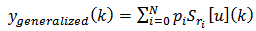
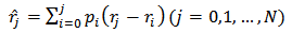
 Since in most practical applications a finite number (N) of hysteresis play operators are used to model hysteresis behavior, the output of the classical Prandtl-Ishlinskii model can also be expressed as:
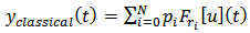 | (3) |
 is the number of the classical play operatorsIn view of the fact that the classical play hysteresis operator has a symmetric unbounded nature, the classical Prandtl-Ishlinskii model cannot characterize the behavior of systems with output saturation or asymmetric hysteresis input-output loops. In order to eliminate these limitations, Brokate and Sprekels [27], and Visitin [28] have suggested an alternative generalized play operator, as a nonlinear play operator, for which the increases and decrease in input
  yields to increase and decrease of the play operator output along the curves
  and
and  respectively (see Figure 2 (b)). The
  and
and  function
  are continuous, bounded and invertible envelope functions over the input domain. According to Equation (2) the output of the generalized play hysteresis operator is analytically expressed for
  as:
as: | Figure 2. Input-Output Relationship of the (a) Classical and (b) Generalized Play Operators |
 | (4) |
 As a result, the output of the generalized Prandtl-Ishlinskii model,
  can be expressed as [26]:
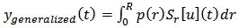 | (5) |
 | (6) |
 is the number of the generalized play operators. As it is clear from Equations (1)-(2) and (4)-(5), the classical Prandtl-Ishlinskii model is a particular case of the generalized Prandtl-Ishlinskii model when identical envelope functions are selected
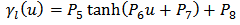
 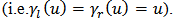 Since the output of the generalized Prandtl-Ishlinskii model strongly depends upon the shape of the envelope function as well as the density function, the shape of these functions should be selected with respect to the hysteretic behavior of material. In addition, in special cases when, like SMA actuators, there is output saturations by increasing and decreasing the input, the hyperbolic tangent functions may be the best choice due to their continuity and bounded properties [26]. Owning to the continuity, bonded and invertible property of these functions, Al Janaideh, Rakheja and Su [26] suggests choosing this function as an envelope function for the shape memory alloy (SMA) actuators. In addition, such functions can facilitate describing the output saturation property available in SMA actuators. Therefore, in this work the following functions are selected for the envelope functions of the generalized play operator:
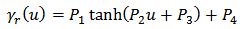 | (7) |
 | (8) |
 | (9) |
 | (10) |
 must be identified using the measured input-output experimental data. In the current research, this training process (or preprocessing process), is performed with the MATLAB optimization Toolbox, in order to minimize error with respect to some experimental data. It should be mentioned that these experimental data are collected from an experimental test set-up, including a flexible beam actuated by two SMA wires, and the details about this set-up are explained in the next section.Zakerzadeh and Sayyaadi [15] have demonstrated that the generalized Prandtl-Ishlinskii hysteresis model is capable in characterizing asymmetric hysteresis nonlinearity of SMA actuators. In the training process the model parameters (like the envelope function parameters as well as the density function parameters) were identified with solving optimization problem to adapt the model response to the experimental data of the real hysteretic behavior (training data) including some first order descending curves attached to the major hysteresis loop. Finally, the generalized hysteresis model responses of the SMA actuator are compared with the training data and the results demonstrated that the developed generalized hysteresis model have very excellent accuracy with respect to the training data. In addition, it was shown that the developed generalized Prandtl-Ishlinskii model leads to good results in predicting high order minor hysteresis loops.
3.2. Inverse Generalized Prandtl-Ishlinskii Model
- In order to compensate the hysteresis behavior of a system completely, it is essential to develop the exact inverse hysteresis model. Generally, as shown in Figure 3, for the hysteresis model
 and inverse hysteresis model
  , the following equation can be obtained if the exact inverse compensator
  exists:
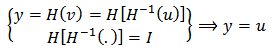 | (11) |
 is the output of the hysteresis model,
  and
and are respectively the input and output of the inverse hysteresis model.
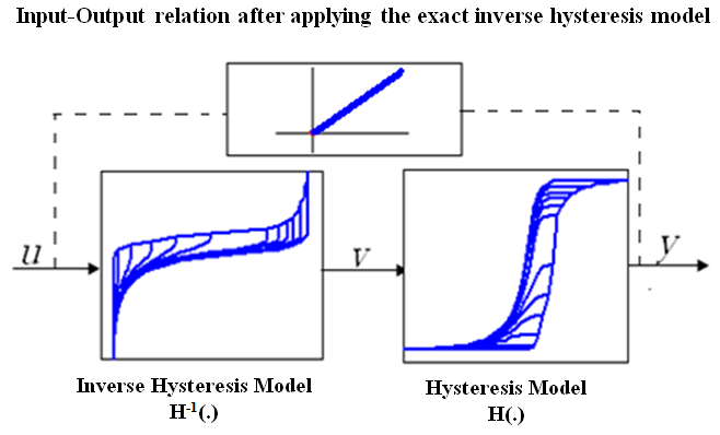 | Figure 3. Compensation of system hysteresis by exact inverse model |
 is formulated in discrete form as [21]:
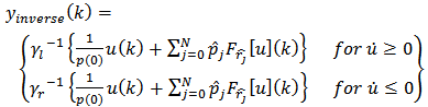 | (12) |
 and
and  are expressed in terms of envelope, density functions and play operator of the generalized Prandtl-Ishlinskii model as [21]:
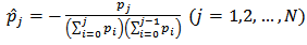 | (13) |
 | (14) |
 is the classical play hysteresis operator that was analytically expressed in equation (2). The details of these equations deviation can be found in Kuhnen and Janocha [32]. As it is clear from equation (12), the inverse generalized Prandtl-Ishlinskii model is a classical Prandtl-Ishlinskii hysteresis model which is defined in terms of density function and threshold function with parameters obtained from equations (13)-(14).
 4. Experimental Test Set-up
- Figure 4 and 5 present a PC-based experimental test set-up and its associated instruments to investigate the capability of the current control system in position control of a flexible smart beam under two SMA wire actuations. As stated in the previous sections in order to have the structure in the large deflection mode, the SMA wires are attached externally. Also, this configuration facilitates the heat transfer of SMA wires, which is in common use. In addition, in order to have a fixed environment temperature, the set-up is covered by clear plexiglass sheets and as a result, the SMA surrounding temperature is fixed at
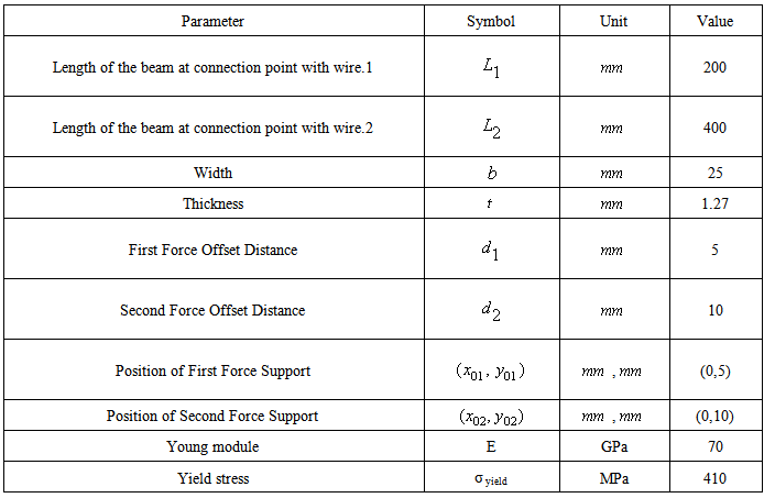
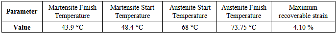
 during all of the experimental tests. According to figure 1, the geometric parameters and material properties of the cantilever aluminum (7075-T6) beam are given in Table 1. The main properties of the SMA wires are also presented in Table 2. The diameter of both SMA wires is 0.254mm (0.01 inch).The SMA wires are placed horizontally (parallel to beam neutral axis) with one end fixed to the beam (the main SMA wire-2 at the end and the auxiliary SMA wire-1 at the middle) and the other end to the base of the beam. Since the available SMA actuator for this set-up has a moderate maximum recoverable strain (about 4%) and the purpose of this study is achieving large deformation of the beam, the length of main SMA wire is enlarged at the back of the beam base (the added length is 55cm) in such a way that the connection point of this wire with the base (point O2 in figure 1) does not change during cooling and heating processes. As a result, the length of the main SMA wire is 95cm and the auxiliary SMA wire is 20cm.
 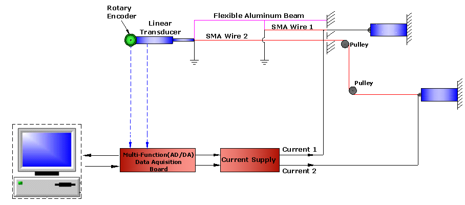 | Figure 4. Schematic of the smart beam set-up actuated by two active SMA actuators |
|
|
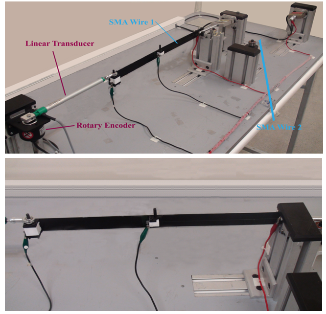 | Figure 5. Experimental test set-up used for training the generalized Prandtl-Ishlinskii model as well as verification of proposed control system |
- Since the tip of the beam does not move on a straight line after the SMA wire actuations, the tip of the beam is connected to a precise frictionless rectilinear displacement transducer (PZ12-A-125, GEFRAN Inc.,) while the other side of the transducer is joined to a high resolution rotary encoder (E50S series, Autonics Corporation). By measuring the length of the transducer and its angle, with respect to their initial quantities, the tip deflection of the beam can easily be computed. In addition, the output voltage of these sensors are fed to a computer-based data acquisition (not shown in Figure 5) using a AD/DA PCI multifunction card (PCI 1711, Advantech Inc.,) and Matlab Data Acquisition Toolbox (Matlab R2008a, Mathworks Ltd.,). The activation electric currents through the SMA wires are set by the computer generated voltages controlling two current amplifiers which are capable of delivering up to 3 Amperes current. The output electric current of these power supplies is proportional to the input voltage. Figure 6 shows the top view of the deformed structure after the heating process of both SMA wires.
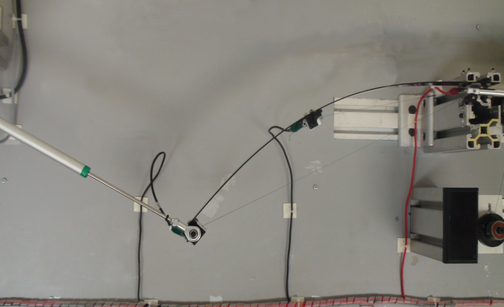 | Figure 6. Top view of the deformed smart beam after two SMA wire actuations |
5. Parameters Identification Process of Generalized Prandtl-Ishlinskii Model
- The objective of this paper is to establish the control system performance when the structure is actuated by two active SMA wires with respect to the case when only one SMA wire is used for deforming the structure. Therefore, different experimental tests must be performed for each case in order to identify the model parameters. In the following sections, Case 1 refers to the time in which only one SMA wire is used to actuate the flexible beam while in Case 2 two active SMA wires is actuating the structure with the same electrical currents. It means that, according to figure 4, in Case 1 the auxiliary SMA wire (wire 1) is not connected to the structure and the main SMA wire (wire 2) solely deforms the structure while in Case 2, in addition to main SMA wire, the auxiliary SMA wire is deforming the beam.
5.1. Identifying the Model Parameters for Case 1
- In order to identify the 11 parameters of the Generalized Prandtl-Ishlinskii model formulated for modeling the saturated hysteresis nonlinearity of SMA actuator, in the training process the electrical current of SMA wire 2 is a slow decaying ramp signal which is shown in figure 7. In this test, the SMA electrical current is increased from the minimum voltage (i.e. zero) up to the current between the maximum current (0.8A) and some lower currents, which leads to some first order descending (FOD) reversal curves attached to the ascending branch of the major loops. From the practical point of view, it is easier to find these curves experimentally than higher-order transition curves and also measurements of these curves start from a well-defined state, namely the state of negative or positive saturation [27]. The change rate of the input voltage is selected so small in order to allow the SMA temperature to stabilize, as in the steady state the SMA temperature will be determined only by the applied electrical current. It should be mentioned here that this input is applied to the system after the first cycle of SMA heating and cooling. Since after the first cycle, the corresponding beam connecting point with the SMA wire has not enough stiffness and flexural rigidity to bring SMA wire back to its initial strain, according to figure 8, the tip deflection of the beam does not start from zero.In the training process of the generalized Prandtl-Ishlinskii model, 435 data set, consisting of the major loop and 10 first order descending (FOD) reversal curves attached to the major loop, is used. The current switching values of these descending reversal curves are selected as: [0.800, 0.667, 0.6, 0.583, 0.567, 0.550, 0.533, 0.517, 0.5, 0.483, and 0.467] (A). For switching values less than 0.467 (A), the change in the beam deflection is not considerable. The experimental input-output hysteresis loops of the flexible beam with SMA wire 2 actuation, under the abovementioned input electrical currents is shown in figure 8. The 11 generalized Prandtl-Ishlinskii model parameters, identified by using MATLAB optimization Toolbox in order to minimize the error between the model output and experimental data, are tabulated in table 3. In addition, the output of the generalized Prandtl-Ishlinskii model in time domain under the input current profile of figure 7, is compared with the experimental data in figure 9. This figure clearly shows that the generalized Prandtl-Ishlinskii model can effectively characterized the hysteresis behavior of the flexible beam structure with one SMA wire actuation. The mean squared value of the absolute error is about 5.4mm.
|
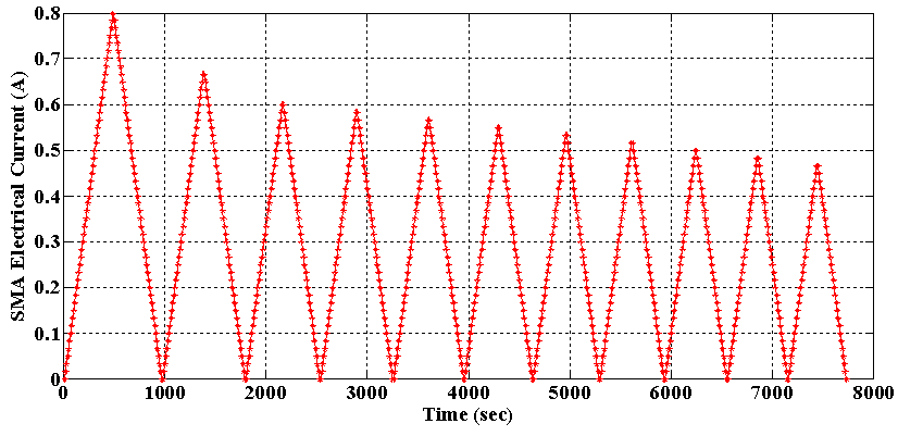 | Figure 7. The decaying ramp input electrical current applied in the training process of Case 1 |
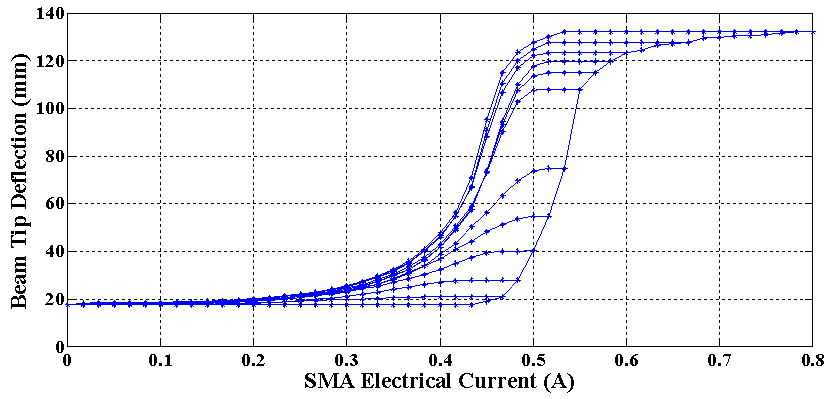 | Figure 8. Experimental data of hysteresis behavior between the beam tip deflection and the SMA electrical current in the training process of Case 1 |
 | Figure 9. Comparison between the deflection predicted by the generalized Prandtl-Ishlinskii model and the training experimental data in Case 1 |
5.2. Identifying the Model Parameters for Case 2
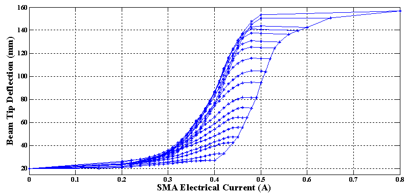
- As mentioned before, in this case the flexible beam is actuated by both of SMA wires while the electrical current of the SMA wires is changed with the same pattern. In this section, in order to show the great ability of generalized Prandtl-Ishlinskii model in describing the hysteresis behavior of systems, the identical envelope functions are selected for increasing and decreasing inputs
 Therefore, the number of generalized Prandtl-Ishlinskii model parameters is decreased to 7 and as a result identifying these parameters by MATLAB optimization Toolbox becomes faster and easier. In order to identify the 7 parameters of the generalized Prandtl-Ishlinskii model in this case, in the training process the input electrical current applied to both of the SMA wires, as in Case 1, is a slow decaying ramp signal which is shown in figure 10. In the training process of Case 2, 492 data set, consisting of the major loop and 17 first order descending (FOD) reversal curves attached to the major loop, is used. The switching current values of these descending reversal curves are selected as: [0.800, 0.650, 0.600, 0.580, 0.560, 0.540, 0.530, 0.520, 0.510, 0.500, 0.490, 0.480, 0.470, 0.460, 0.450, 0.440, 0.420, 0.400] (Amp). The experimental input-output hysteresis loops of the flexible beam with both SMA wires actuation, under the abovementioned input electrical current is shown in figure 11. The 7 generalized Prandtl-Ishlinskii model parameters, identified by using MATLAB optimization Toolbox in order to minimize the error between the model output and experimental data, are tabulated in table 4. In addition, the output of the generalized Prandtl-Ishlinskii model in time domain under the input current profile of figure 10, is compared with the experimental data in figure 12. This figure clearly shows that, even in this case that the generalized Prandtl-Ishlinskii model has less parameters, it can effectively characterized the input-output hysteresis behavior of the flexible beam actuated with two active SMA wires. The mean squared value of the absolute error in this case is slightly more than the first case (as a result of using fewer model parameters) and is about 9.16mm.
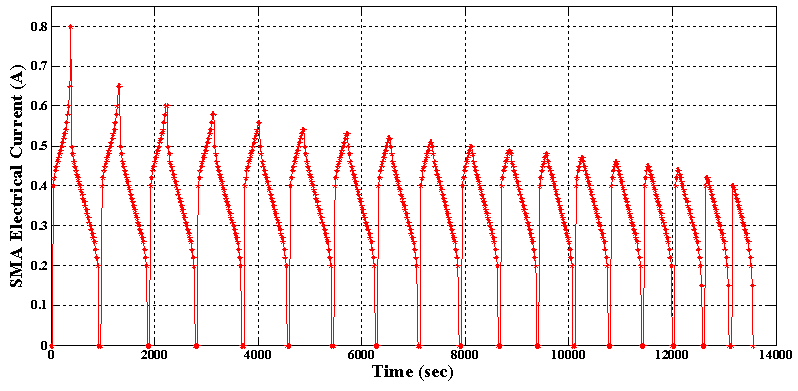 | Figure 10. The decaying ramp input electrical current applied to both SMA wires in the training process of Case 2 |
 | Figure 11. Experimental data of hysteresis behavior between the beam tip deflection and the electrical current of both SMA wires in the training process of Case 2 |
 | Figure 12. Comparison between the deflection predicted by the generalized Prandtl-Ishlinskii model and the training experimental data in Case 2 |
|
6. Experimental Validation of the Proposed Control System
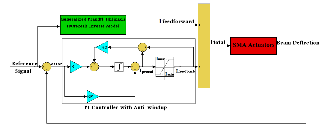
- As mentioned before, using the inverse hysteresis model is an effective method to compensate the hysteresis behavior of smart actuators. In view of the fact that the generalized Prandtl-Ishlinskii model has the advantage of analytically invertible and also has more accuracy for hysteresis modeling of SMA actuator with respect to the Preisach and Krasnosel'skii-Pokrovskii hysteresis models [15], especially for high order minor loop prediction, in this research the inverse of generalized Prandtl-Ishlinskii model is used for canceling up the hysteresis nonlinearity of SMA-actuated flexible beam. However, from practical point of view, the inverse hysteresis model cannot cancel the hysteresis nonlinearities in the SMA actuators completely. As a result, in this paper, for Case 1 and Case 2, the inverse of hysteresis model is incorporated in a closed-loop proportional-integral (PI) controller with anti-windup to increase the accuracy of tracking in addition to eliminate the steady state error for position control of the smart flexible beam deflection. The block diagram of the proposed controller, for both cases, is shown in figure 13. The command reference displacement is used as the input of the inverse generalized Prandtl-Ishlinskii model. This inverse model generates the required control current signal for tracking the desired trajectory. The total currents applied to the SMA actuators are:
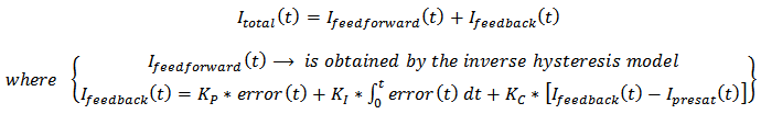 | (15) |
 is the compensating electrical current, developed by inverse of the generalized Prandtl-Ishlinskii hysteresis model, applied to the SMA wires which can be used to compensate the hysteresis nonlinearity of the SMA actuators. The error between the desired command displacement and the output of the system (beam deflection) is the input of the PI controller with anti-windup while
  is the output current of this controller delivered to both SMA wires. The integral, proportional and the integral correction (anti-windup) gains of the PI feedback controller, denoted by
 and
and  respectively are
  and
and  The values of these gains are set in such a way that system response to step command input has the minimum overshoot as well as quick response. The output of the PI controller with anti-windup before saturation is denoted by
  In addition, the upper and lower bounds of this controller output, denoted by
  and
and  in figure 13, is selected as
  and
and  respectively. The total current applied to the SMA actuators,
  is the sum of electrical currents created by feedforward controller
  and feedback controller
  In order to prevent SMA overheating, the upper bound of this electrical current is chosen as
 | Figure 13. Closed-loop control system scheme applied in Case 1 and 2 for position control the tip deflection of smart flexible beam |
 which forces the inverse hysteresis model to predict a hysteresis loop with no higher order minor loops in it. The experimental result of the proposed control system for both cases is investigated for
  and is shown in figure 14. The absolute value of the position error for both cases is also depicted over time in figure 15.
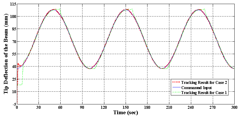 | Figure 14. Tracking result of the proposed control system for Case 1 and Case 2 in test 1 with  |
 | Figure 15. Absolute of tracking error for Case 1 and Case 2 in test 1 with  |
|

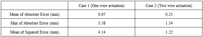
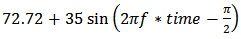
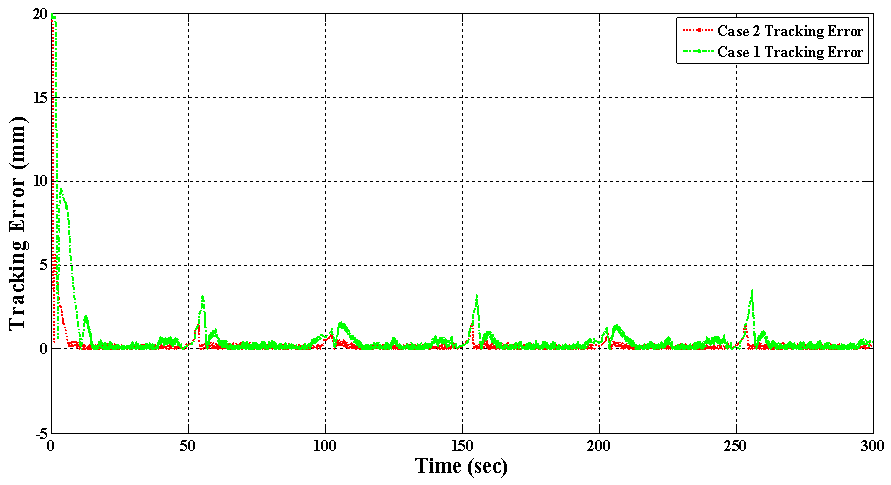
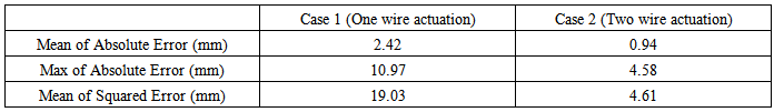
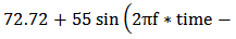
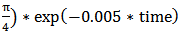
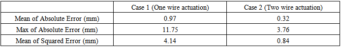
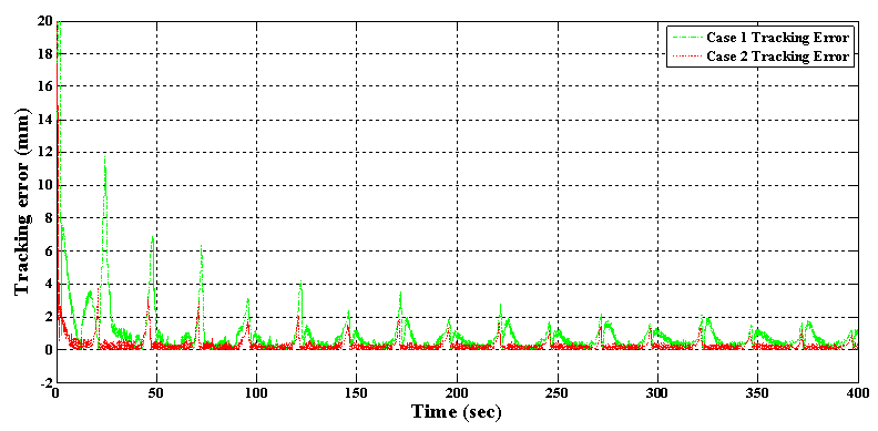
 . Since the purpose of this research is establishing the proposed control system in the new architecture for deflection control of beam-like structures in large deflection mode, the tracking performance in high frequency command inputs is not considered here. In addition, the tracking frequency of 0.04 Hz is suitable for many applications like morphing wings. The experimental result of the proposed control system in tracking such sinusoidal command input for both cases is depicted in figure 16. Also the absolute value of the tracking position error over time is shown in figure 17. It is obviously observable from these figures that, although in both cases tracking such fast command input is more difficult for the proposed control system, in such high frequency command input the proposed control system has better tracking accuracy in Case 2 rather than the Case 1. The mean of absolute error, maximum of absolute error (after initial transition response) and mean of squared error are also shown for both cases in table 6. The absolute error average for the Case 1 is 2.42 mm while this value has decreased to 0.94 for Case 2. It signifies that in tracking such high frequency command input, adding the auxiliary SMA wire has improved the mean of absolute value of the tracking error by 62%. Also, the value of maximum error (after initial transition response) is 10.97 mm for the Case 1 while this value is 4.58 mm for Case 2 which shows 58% improvement. In addition, the mean of squared error has decreased by 76% from Case 1 to Case 2. It is worth mentioning here that such improvement in the tracking result of this test has been obtained only by attaching one auxiliary SMA wire to the structure whose length is about 20% of the main actuator and also fewer model parameters are used for generalized Prandtl-Ishlinskii model in Case 2 in comparison to Case 1. This is a novel idea for increasing the position control accuracy in smart structures actuated by SMA wires.
 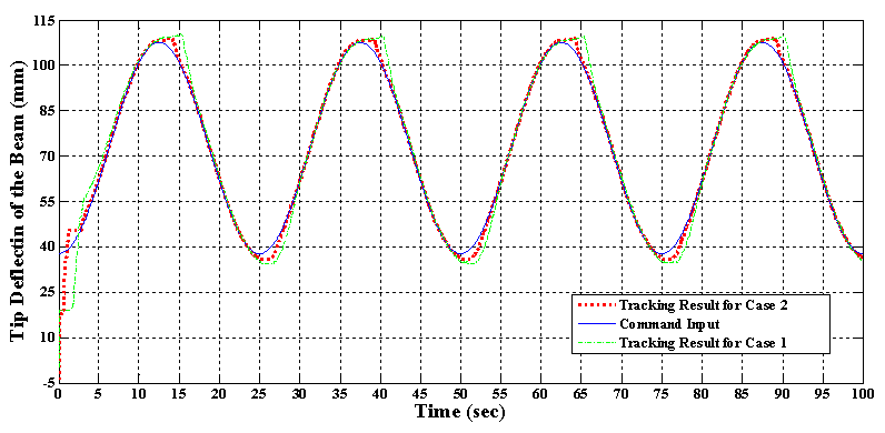 | Figure 16. Tracking result of the proposed control system for Case 1 and Case 2 in test 1 with  |
|

 with
with  which not only is a decaying input but also its variation with respect to the time is almost fast. Therefore, the response of the control system to this fast decaying input can verify the performance of the controller. The experimental result of the proposed control system in the case that one active SMA actuator is present (Case 1) and in the case where both of SMA actuators are deforming the structure (Case 2) is shown in figure 18. As it is clear the control system has good performance for both cases but in the Case 2 the system has more ability to track such command input. It should be mentioned that this valuable result is acquired by only training the Prandtl-Ishlinskii hysteresis model with the data of some first order reversal curves. The similar results are also reported by Zakerzadeh and Sayyaadi in [15]. In addition, since the number of parameters used in generalized Prandtl-Ishlinskii model in Case 2 is less than Case 1, this accurate tracking result for Case 2 becomes more valuable.
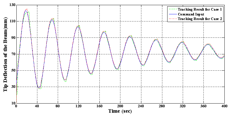 | Figure 18. Tracking result of the proposed control system for Case 1 and Case 2 in test 2 |
|
 | Figure 19. Absolute of tracking error for Case 1 and Case 2 in test 2 |

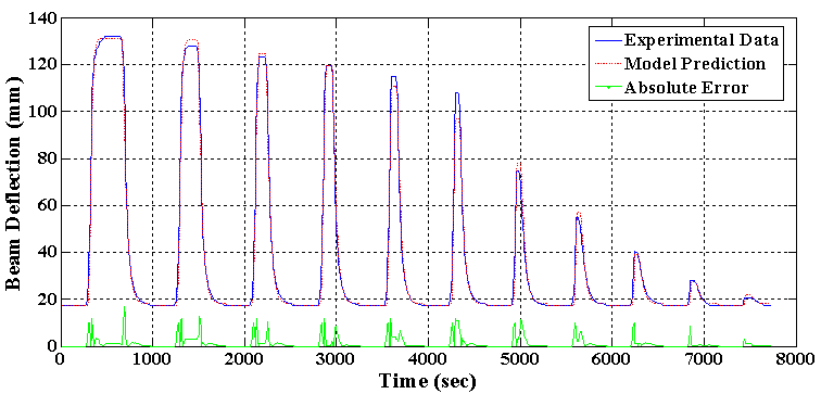
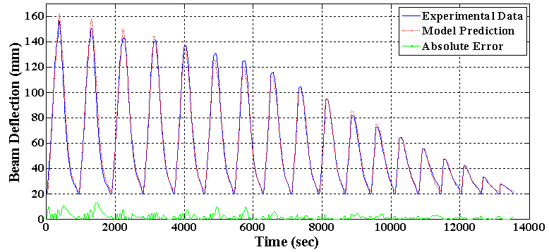
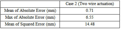
 This command input is not only a fast decaying sinusoidal trajectory which results to predicting some high order minor hysteresis loops by the inverse hysteresis model, but also the tracking of this command signal is performed in large deformation mode of the structure. Since, using only the main SMA actuator (i.e. Case 1) cannot deform the flexible beam to this large deflection, the result of Case 2, where both of SMA wires actuate the structure, is brought here. The experimental result of the proposed control system in tracking the command input in Case 2 in which both of SMA actuators are deforming the structure is shown in figure 20. The absolute value of the position error over time is also shown in figure 21. The mean of absolute error, maximum of absolute error (after initial transition response) and mean of squared error in this test are also shown for Case 2 in table 8. As it is clear from these figures, the proposed control system, consisting the inverse hysteresis model as a feedforward controller and the simple feedback proportional-integral (PI) controller, can effectively control the tip deflection of the beam in the large deformation mode of the structure by using two active SMA wires. According to table 8, the mean and maximum values of the absolute error are, respectively, 0.71 mm and 6.55 mm which are about 0.5% and 4.6% of the maximum deflection of the beam (143mm), respectively.
 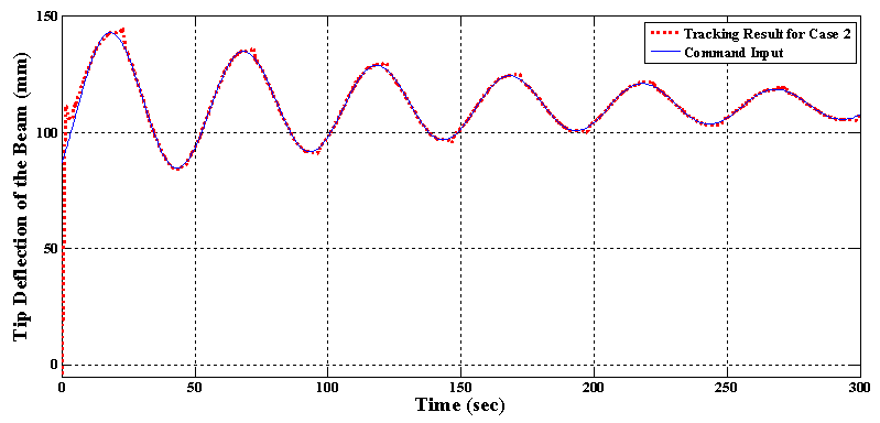 | Figure 20. Tracking result of the proposed control system for Case 2 in test 3 |
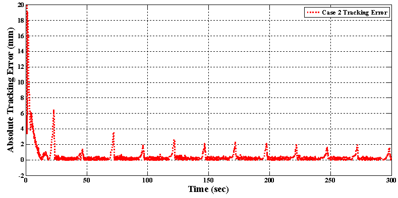 | Figure 21. Absolute of tracking error for Case 2 in test 3 |
|
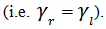
- Eventually, the control output applied by the feedforward part, feedback part and whole controller to each of SMA wire (according to figure 13 and equation (15)) is shown in figure 22. As it is apparent, the major portion of the applied electrical current
 belongs to the feedforward controller
  and the PI controller current output
  only has the role of reducing the tracking error and helps achieve more accurate tracking results, while if the conventional PI controller is lonely used in the control process, all of the control effort must be supported by the feedback controller.
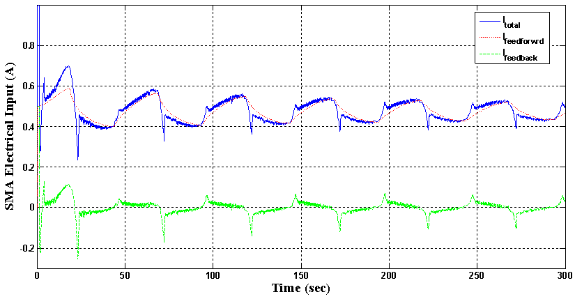 | Figure 22. Control output applied by each portion of the proposed control system to both of the SMA actuators for experiment test 3 |
7. Conclusions
- As discussed extensively in this article, the most difficult challenging point in position control of smart structures in large deformation mode is their great sensitivity to smart actuator force as well as their highly nonlinear behaviors of both SMA actuator and flexible structure accordingly. In this paper, hysteresis nonlinearity of SMA-actuated flexible structure was modeled by the generalized Prandtl–Ishlinskii model. Consequently, a feedforward–feedback controller was used to control the tip deflection of the beam-like SMA-actuated structure. The feedforward part of the controller was based on the inverse generalized Prandtl – Ishlinskii model while a conventional proportional–integral feedback controller was added to the feedforward control system to increase the accuracy together with decreasing the steady state error in position control process. Besides, in order to eliminate the nonlinear behavior in large deflection of flexible structure, another auxiliary SMA actuator was attached to the whole structure and position control of tip end of flexible beam structure was examined accordingly. As a result, precise position control of flexible structures, especially SMA-actuated ones, is the challenging point of the current studies. According to the reported results of the current research and former one by authors around SMA-actuated structures [5], implementing additional SMA actuator as an auxiliary actuator in parallel to the main implemented SMA actuator, namely existing two SMA actuators, perform much accurate in tip control of a flexible beam structure in both small and large deformation modes. It means simply that performing tip control of flexible structure using two parallel SMA actuators bring simultaneously reasonable accuracies in both ranges of control interests named, small and large modes of smart structures. Besides, using the aforementioned control architecture of two SMA actuators causes less sensitivities to actuators forces during small and large deformation modes.In this paper, due to the exact invertible property of the generalized Prandtl-Ishlinskii model, its inverse model was used as a feedforward controller to omit the hysteresis behavior of a flexible structure actuated by two active SMA actuators. Moreover, in order to have a precise position control and also to remove the steady state error in the new architecture of the structure, this feedforward compensator was incorporated with a conventional feedback Proportional-Integral (PI) controller. The experimental results demonstrate that using the proposed feedforward - feedback control system in the structure with two active SMA actuators can greatly improve the performance of the position control system in comparison to the case where only one active SMA wire was used. Using the proposed control system in the new architecture has great abilities in tracking sinusoidal trajectory with low and high frequencies and in tracking trajectories which force the inverse model to predict high order minor hysteresis loops. It was shown experimentally that in comparison to the structure having one SMA wire, the improvement in the mean position error is more than 62% and the decrease in the extremum of the position error is more than 57%. Great achievements were also attained in tracking trajectory in large deformation mode of the structure where many control systems have weak performance in these regions. These results become more valuable when we know that the length of the auxiliary SMA wire has been only 20% of the main actuator and also less model parameters were used in the proposed control system.