Rajesh C. Shah1, Nayan I. Patel2, 3
1Department of Applied Mathematics, Faculty of Technology and Engineering, The M. S. University of Baroda, Vadodara, Gujarat State, 390001, India
2School of Engineering, R.K.University, Rajkot, Gujarat State, India
3Department of Mathematics, Silver Oak College of Engineering and Technology, Gota, Ahmadabad, Gujarat State, 382481, India
Correspondence to: Rajesh C. Shah, Department of Applied Mathematics, Faculty of Technology and Engineering, The M. S. University of Baroda, Vadodara, Gujarat State, 390001, India.
| Email: |  |
Copyright © 2012 Scientific & Academic Publishing. All Rights Reserved.
Abstract
This paper discusses about the slider bearing of various shapes stator pad surfaces (e.g. inclined plane, exponential, secant, convex, and parallel) including combined effects of porosity at both the ends, anisotropic permeability, slip velocity, and squeeze velocity. Expression for load capacity is obtained in general and discussed for various cases of stator pad surface to explore its possible effects on the above system for different permeabilities at both the ends. Various sizes of the porous matrix at both the ends are also discussed for the possible optimization of bearing performance. From the study we conclude that better load capacity is obtained when the thickness of both the porous plates are small, and also when both the porous plates are of same size rather than different size.
Keywords:
Porosity, Inclined Bearing, Anisotropic Permeability, Slip Velocity
1. Introduction
Wu[1] in an innovative analysis, dealt with the case of squeeze film behavior for porous annular disks in which he showed that owing to the fact that fluid can flow through the porous material as well as through the space between the bounding surfaces, the performance of a porous walled squeeze film can differ substantially from that of a solid walled squeeze film. Later Sparrow et. al.[2] extended the above analysis[1] by introducing the effect of velocity slip to porous walled squeeze film with porous matrix appeared in the above plate. They found that the load capacity decreases due to the effect of porosity and slip. Prakash and Vij[3] investigated a porous inclined slider bearing and found that porosity caused decrease in the load capacity and friction, while it increased the coefficient of friction. Many other authors have also worked in this direction, for example Patel et. al.[4], Gupta et. al.[5], Naduvinamani et. al.[6], Guo. et. al.[7].In all above investigations, none of the authors considered both the porous plates in their study. The porous layer in the bearing is considered because of its advantageous property of self lubrication. With this motivation the aim of thepresent work is to study the behavior of a slider bearing of various stator pad surfaces with the porous matrix attached to both the plates (that is upper and lower). Here, we have also included the effects of slip velocity and anisotropic permeability at both the porous plates, as well as squeeze velocity when the upper plate approaches to lower one.A lubrication equation is derived in general for the above system. The various shapes of the slider bearing due to different stator pad surfaces is considered for the study of load capacity with various sizes of upper and lower porous matrix. Moreover, two different cases of anisotropic permeability at upper and lower porous matrix is also considered for study.
2. Formulation of the Mathematical Model
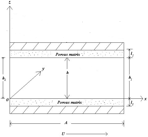
Figure 1-5 shows schematic diagram of various system under study which consists of a fluid film of thickness h within an stator pad surface of various shapes and a slider of length A in the x-direction and width B in y-direction, A<< B. The value of h is h2 at the inlet and h1 at the outlet. This film thickness h are given as follows:(a) For inclined pad slider bearing: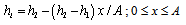 | (1) |
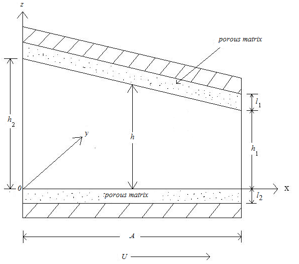 | Figure 1. Inclined pad slider bearing |
(b) For exponential pad slider bearing: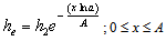 | (2) |
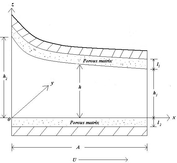 | Figure 2. Exponential pad slider bearing |
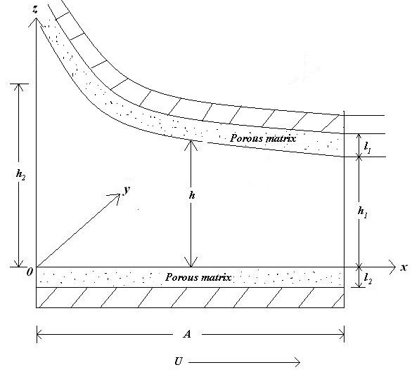 | Figure 3. Secant pad slider bearing |
(c) For secant pad slider bearing: | (3) |
(d) For convex pad slider bearing: | (4) |
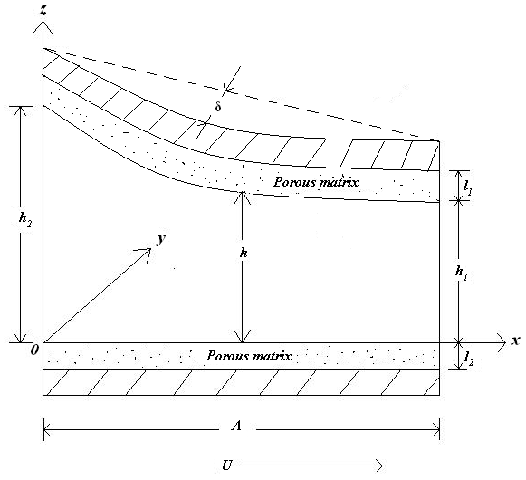 | Figure 4. Convex pad slider bearing |
where δ is the central thickness of the convex pad.(e) For parallel pad slider bearing: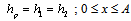 | (5) |
 | Figure 5. Parallel pad slider bearing |
Porous matrix of thickness l2 and l1 metres have attached with the slider and stator respectively. Both the porous matrix are backed by a solid wall. The slider moves with a uniform velocity U in the x-direction. Also, stator moves normally towards the slider with a uniform velocity , where t is time in seconds.The basic one dimensional flow equation governing the lubricant flow in the film region for the above phenomenon follows form Navier-Stokes’s equation under the usual assumption of lubrication, neglecting inertia terms and that the derivatives of velocities across the film predominate, yields
 | (6) |
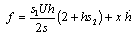
where u is the film fluid velocity in the x-direction, p is film pressure and  is fluid viscosity.Solving equation (6) under the slip boundary conditions given by Sparrow et.al.[2] and modified by Shah et.al.[8] with the addition of slider velocity U to[2]where
 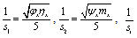 (i =1, 2), being slip parameter,
  are porosities in the x- direction and
  are permeabilities in the x- direction in the porous region, we obtain
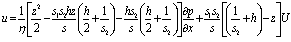 | , (8) |
where  Substituting the above value of u in the integral form of continuity equation
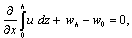 | (9) |
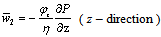
where w is the axial component of the fluid velocity in the film, we have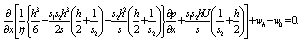 | (10) |
Using Darcy’s law, the velocity components of the fluid in the porous matrix are given as follow:For upper porous region: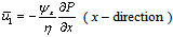 | (11) |
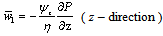 | (12) |
where  are fluid permeabilities in the upper porous region in x and z direction respectively, and P is the fluid pressure in the porous region.
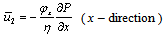 | (13) |
 | (14) |
where  are fluid permeabilities in the lower porous region in x and z direction respectively, and P is the fluid pressure in the porous region.Substituting equations (11) and (12) in the continuity equation for upper porous region
 | (15) |
and then integrating the result with respect to z across the upper porous matrix ( h, h+l1 ), we obtain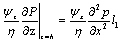 | (16) |
using Morgan-Cameron approximation[6] and the fact that the surface  is non-porous.Substituting equations (13) and (14) in the continuity equation for lower porous region
 | (17) |
and then integrating the result with respect to z across the lower porous matrix ( l2, 0), we obtain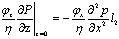 | (18) |
using Morgan-Cameron approximation[6] and the fact that the surface  is non-porous.Considering the normal component of velocity across the film porous interface are continuous, so that
 using equations (16), (18) and (10), we obtain
 | (19) |
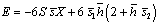
where 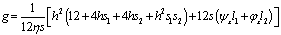 ,
,  ,which is the Reynolds’s type equation for the considered phenomenon.Introducing the dimensionless quantities
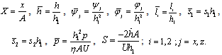 We have from equations (1)-(5),
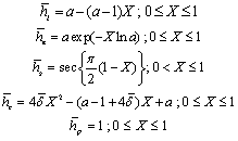 where
where Also, equation (19) transforms to
 | (20) |
where 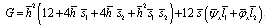 ,
,  Equation (20) is known as dimensionless Reynolds’s equation.
3. Calculation of Load Capacity
Since the pressure is negligible on the boundaries of the slider bearing compared to inside pressure, solving equation (20) under boundary conditions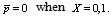 The dimensionless film pressure
  is obtained as:
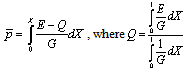 The load carrying capacity W in dimensionless forms as
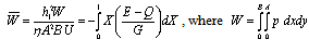
4. Results and Discussion
Both porous plates various slider bearing with slip velocity, anisotropic permeability, squeeze velocity lubricated by a conventional fluid are examined to explore the possible effects on the bearing characteristic like load capacity. The dimensionless load capacity  for various bearings denoted as follows:
 - Dimensionless load capacity for inclined pad stator slider bearing
 - Dimensionless load capacity for exponential pad stator slider bearing
 - Dimensionless load capacity for secant pad stator slider bearing
 - Dimensionless load capacity for convex pad stator slider bearing
 - Dimensionless load capacity for parallel pad stator slider bearingThe values of dimensionless load capacity
  for various bearings are calculated as follows:(1) For various values of
  (m2) keeping
  =0.000001 (m2) fixed and for the cases(a)
  = 5,
= 5,  = 5 (Refer Table 1)(b)
  = 5,
= 5,  = 10 (Refer Table 2)(c)
  = 10,
= 10,  = 5 (Refer Table 3)(2) For various values of (m2) keeping =0.000001 (m2) fixed and for the cases(a)
  = 5,
= 5,  = 5 (Refer Table 4)(b)
  = 5,
= 5,  = 10 (Refer Table 5)(c)
  = 10,
= 10,  = 5 (Refer Table 6)For various values of
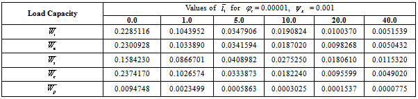
  keeping
  = 5 fixed and for the cases(a)
  =0.001(m2),
  =0.00001(m 2) (Refer Table 7)(b)
  =0.00001(m 2),
  =0.001(m 2) (Refer Table 8)(4) For various values of keeping = 5 fixed and for the cases(a)
  =0.001(m2),
  =0.00001(m 2) (Refer Table 9)(b)
  =0.00001(m 2),
  =0.001(m 2), (Refer Table 10)The values of the various parameters used are as follows:
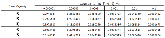
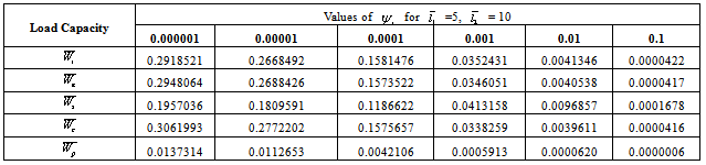
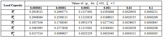
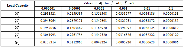
 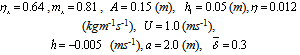 From the Table 1 to 10 we have following observations:From Table 1 to Table 3 we say that maximum load capacity obtained for all types of bearings when
  =0.000001(m2) and in that case
 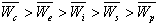 When the value of
  increases then for all cases the load capacity decreases.
Table 1. Values of
 for for
 = 0.000001 = 0.000001
 |
| |
|
Table 2. Values of
 for for
 = 0.000001 = 0.000001
 |
| |
|
Table 3. Values of
 for for
 = 0.000001 = 0.000001
 |
| |
|
Table 4. Values of
 for for
 = 0.000001 = 0.000001
 |
| |
|
Table 5. Values of
 for for
 = 0.000001 = 0.000001
 |
| |
|
Table 6. Values of
 for for
 = 0.000001 = 0.000001
 |
| |
|
Table 7. Values of
 for for
 = 5.0 = 5.0
 |
| |
|
Table 8. Values of
 for for
 = 5.0 = 5.0
 |
| |
|
Table 9. Values of
 for for
 = 5.0 = 5.0
 |
| |
|
Table 10. Values of
 for for
 = 5.0 = 5.0
 |
| |
|
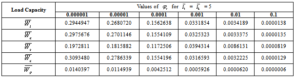
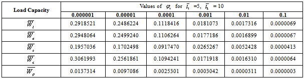
From Table 4 to Table 6 we say that maximum load capacity obtained for all types of bearings when  =0.000001(m2) and in that case
  When the value of
  increases then for all cases the load capacity decreases.From Table 7 and Table 8 we say that maximum load capacity for all shapes of bearing is obtained when
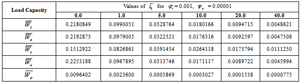
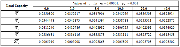
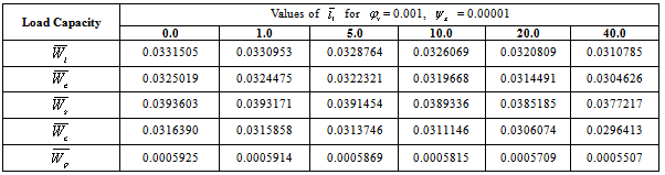
  = 0 that is when there is no porous matrix on the slider. In general when the width of the porous matrix is small, the load capacity increases.The same behavior for load capacity obtained for Table 9 and 10.
5. Conclusions
Based upon the above formulation, and results & discussion, the conclusions can be drawn as follows for designing various slider bearings:(1) Because of having the self lubrication property of the porous plate bearing, it is suggested to have both the porous plate bearing for better self lubrication.(2) Better load capacity is obtained when the thickness of l1 and l2 is small.(3) Better load capacity is obtained when l1 = l2 as compare to l1 < l2 and l1 > l2 .(4)The order of increase of load capacity for various bearings are as follows.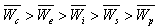
References
| [1] | H. Wu, Squeeze - film behavior for porous annular disks, Journal of Lubrication Technology, Trans. ASME, Series F, 92(4) (1970) 593-596. |
| [2] | E. M. Sparrow, G. S. Beavers, I. T. Hwang, Effect of velocity slip on porous walled squeeze films, Journal of Lubrication Technology 94 (1972) 260-265. |
| [3] | J. Prakash, S. K. Vij, Hydrodynamic lubrication of a porous slider, Journal of Mechanical Engineering Science 15 (1973) 232-234. |
| [4] | K. C. Patel, J. L. Gupta, Hydrodynamic lubrication of a porous slider bearing with slip velocity, Wear 85 (1983) 309-317. |
| [5] | R. S. Gupta, P. Kavita, Analysis of rotation in the lubrication of a porous slider bearing: small rotation, Wear 111 (1986) 245-258. |
| [6] | N.B. Naduvinamani, S. T. Fathima, S. Jamal, Effect of roughness on hydromagnetic squeeze films between porous rectangular plates, Tribology International 43 (2010) 2145–2151. |
| [7] | F. Guo, P. L. Wong, M. Geng, M. Kaneta, Occurrence of Wall Slip in Elastohydrodynamic Lubrication Contacts, Tribol. Lett. (2009) 34:103–111. |
| [8] | R. C. Shah, M. V. Bhat, Ferrofluid lubrication equation for porous bearing considering anisotropic permeability and slip velocity, Indian Journal of Engineering & Material Sciences 10 (2003) 277-281. |
 Abstract
 Reference
 Full-Text PDF
 Full-Text HTML