-
Paper Information
- Paper Submission
-
Journal Information
- About This Journal
- Editorial Board
- Current Issue
- Archive
- Author Guidelines
- Contact Us
American Journal of Biomedical Engineering
p-ISSN: 2163-1050 e-ISSN: 2163-1077
2016; 6(5): 139-146
doi:10.5923/j.ajbe.20160605.02

Controlling a Servo Motor Using EEG Signals from the Primary Motor Cortex
 Abstract
 Reference
 Full-Text PDF
 Full-text HTML
Somer M. Nacy, Sadeem N. Kbah, Hind A. Jafer, Ibraheem Al-Shaalan
Biomedical Engineering Department, Alkhwarizmi College of Engineering, University of Baghdad, Baghdad, Iraq
Correspondence to: Somer M. Nacy, Biomedical Engineering Department, Alkhwarizmi College of Engineering, University of Baghdad, Baghdad, Iraq.
| Email: |  |
Copyright © 2016 Scientific & Academic Publishing. All Rights Reserved.
This work is licensed under the Creative Commons Attribution International License (CC BY).
http://creativecommons.org/licenses/by/4.0/

Brain Computer Interface means the group of processes in which the generated signals of EEG in the human brain can be interpreted and transferred to control an external device. In this paper, a novel method is adopted to control the rotation of a servo motor via EEG signals extracted from the human brain cortex. These signals have to pass through a processing procedure consisting mainly noise filtration and signal normalizing. The processed signal is fed to Arduino, which in turn controls the servo motor rotation.
Keywords: Brain Computer Interface, EEG signal, Motor cortex
Cite this paper: Somer M. Nacy, Sadeem N. Kbah, Hind A. Jafer, Ibraheem Al-Shaalan, Controlling a Servo Motor Using EEG Signals from the Primary Motor Cortex, American Journal of Biomedical Engineering, Vol. 6 No. 5, 2016, pp. 139-146. doi: 10.5923/j.ajbe.20160605.02.
Article Outline
1. Introduction
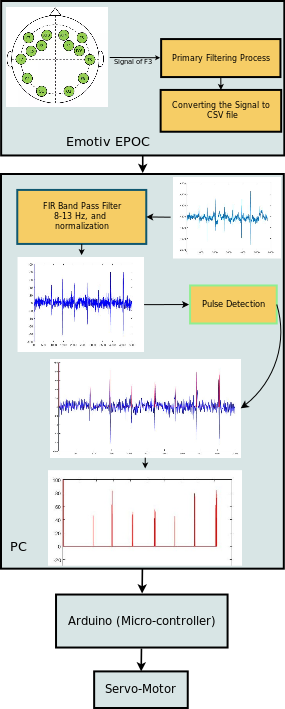
- The human brain is the most developed and sophisticated part in the human body, it starts to show an electrical activity between (17-23) week in the embryonic time, when the baby born he has up to 1011 neuron with (5x10¹⁴) synapses [1]. The human brain controls all the body functions and movements, however limbs and other parts of the human body can stop functioning totally because of the lose of connections between parts of the brain and these limbs and organs due to any damage in the nervous system, which will leave the body paralysed and not capable of doing daily life functions [2].The first Brain-Computer Interface (BCI) as an idea was described by Dr. Grey Walter in 1964, however started as a wide research field since the 70’s of the last century [3], after EEG signal was recorded from all lobes of the cortex for the first time by Beryer in 1943 [4]. The first description and first recording of an electrical signal from the motor cortex was done by Dr. Walter and had been done by asking a volunteer under open brain surgery to press a bottom and record the electrical activity of the cortex region [5]. Another kind of computer-human interface had been produced, like using of human skin as touch interface [6], or controlling a wheelchair using the tongue [7], also using an eye-tracking system in human-computer interface [8]. Vernon and Joshi used an over ear muscle to control a television [9].The BCI has been acheived using many devices, like EEG, MEG and fMRI [10], however EEG considered as the most suitable one since it is non-invasive, low cost compared to other modalities specially fMRI, portability and ease of use [11]. Nowadays there are a lot of research centers all over the world that work to develop the Brain-Computer Interface since this subject has a lot of importance in the field of human brain studying and understanding its emotions [12], in addition to that it has an importance to improve the life of amputee people who have serious problems in living their lives normally and do all the normal functions [13]. In this paper we introduced a novel method of controlling a servo motor using the EEG signals taken directly from the cortex of the brain, which can be later attached to an artificial hand as a biomedical application. It can be considered as a new and more difficult method, yet necessary since some people loses all their limbs due to an accident, which makes it difficult and near impossible to take and EMG recording from the rest of their limbs. Our method is illustrated in brief in Figure (1). The process we passed through in order to obtain our final pulses was to prepare the EEG recording device to ensure obtaining a signal in a readable format, then we chose the channel that is related to the motor cortex part of the brain and eliminate the others to reduce the internal noise of the device. The obained signal then was fed to a PC to do the required processing and pulse extraction to control the motion of a servo motor using Arduino.
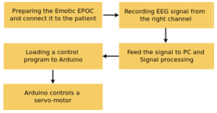 | Figure 1. Flow-chart of the work |
2. The Brain Cortex
- The cortex is the most outer part of the grey matter in the brain, it covers the other parts of the brain with a layer of (2-3) mm in thickness, Figure (2). The cortex consists of regions that can be classified according to the complexity of the functions they do to primary cortices and associated cortices. Primary cortices are more involved in receiving the sensing signals from parts of the human body and are located to the posterior parts of the brain, while the associated cortices are responsible for more complex functions like memorizing, thinking and decision making and are located mostly in the anterior superior parts of the brain.
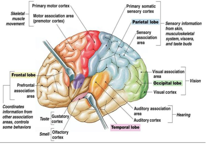 | Figure 2. The human brain cortex and its parts [16] |
3. Electroencephalography (EEG)
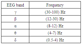
- The EEG is a medical method used to record the electrical activity of human brain cortex due to the presence of action potential [2]. The EEG signal is very important since it is used for research as in studying of cortical parts functions like understanding specific properties, such as attention, alertness, mental acuity. It is used also for diagnostic purposes, diagnosis of epilepsy and other brain traumas. However, it is considered as one of the lowest biological signals when it comes to its amplitude (0.5-100 µ)V, which makes it very difficult to record [17].The EEG signal represents the aggregation of multiple action potentials of single neurons, accumulated in one electrical wave and arranges in frequency bands as in Table (1) and as presented graphically in Figure (3).
|
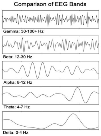 | Figure 3. This Frequency bands of EEG signal [22] |
3.1. Choice of Alpha Wave
- Alpha wave (α) lies in between the (β) and (θ) waves with an amplitude of (30-50) µV [22], so when the (α) wave is dominant the brain will be in transition zone between the conscious and subconscious states, which is the best time to do mental relaxation. The (α) wave also dominates during the meditation and physical exercises [21], that is why we chose it in our study to be the controlling wave of our servo motor, which will be later attached to an artificial hand.Controlling a servo motor (and later an artificial hand) by using EEG signal requires a full awakens from the person under EEG test, since that person needs to learn to make some kind of control of his own EEG waves and make a conscious thinking of the actions he wants to do, thats why we chose (α) wave as our reference wave to be analysed and to control the later coming actions on the servo motor.
3.2. Types of EEG Electrodes
- There are many types of electrodes, which can be divided mainly to surface electrodes and sub-dermal or needle electrodes [23].Ÿ Reusable disks.Ÿ EEG Caps with disks.Ÿ Adhesive Gel Electrodes.Ÿ Sub-dermal Needles.The type adopted in this study is the EEG Caps with disks which are surface electrodes, in the Emotiv EEG recording device [24].
4. EEG Artifacts
- As it is well known, the EEG signal is considered as the weakest signal among the human biosignals, and it is very likely to be interfered with other internal biosignals and other external signals specially those with the same range of frequencies.In order to treat all sources of artifacts added to the EEG signal, it is useful to classify them as BIOLOGICAL and EXTERNAL. The main sources of noise added to EEG signal are [17]:Ÿ Eye movement artifacts: One of the most common problems in EEG recording process is the eye movements artifacts, which will add a rapid signal with ~100 µV to our signal. The eye movement artefacts appears when ever the volunteer blinks or move his eye or eyelids. Normally the closure the recording electrodes to the eye the stronger the recorded noise will be.Ÿ Cardiogenic Artifacts: Which are the artefacts results from the electrical activity of the heart, it has a much larger amplitude than the EEG with near by frequencies. The good thing about ECG is that it could be detected by bare eyes since it has a fixed rhythms (QRS).Ÿ Muscle movements artifacts: EMG wave also can be interfered with EEG signals, specially those in the cranial (head and neck) region since these movements are irregular and normally have low frequency values, which will interfere with the low frequency components of the recorded EEG signal.We have also external noise, which is the noise added from the electromagnetic signals outside the human body which are:Ÿ Environmental noise: Since the EEG signal is an electromagnetic signal, so any kind of signal available in the outside environment will affect the EEG test. Specially those have a relatively low value of frequency like the 50 Hz power-lines, other electronic devices like laptop PCs and other medical devices in the hospital room can also make a noise interference to our EEG measurement. We can get rid of such noises by using notch filters.Ÿ Problems due to electrode-scalp contact: It is of great importance to make sure that all the electrodes have a good contact with the scalp, otherwise a capacitive effect will occur and make an additional noisy effect to the main EEG signal.
5. The Used EEG Device
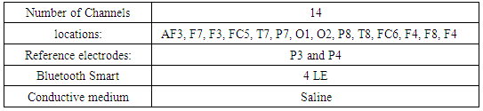
- The device used in this research is the EMOTIV EPOC as depectied in Figure (4). It is a scientific contextual EEG, easy to use and has a reasonable accuracy [24]. The Emotiv EPOC specific properties are as mentioned in Table (2), the electrode locations are shown in Figure (5).
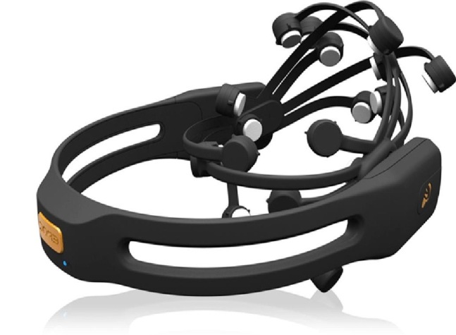 | Figure 4. The Emotiv EPOC device [24] |
|
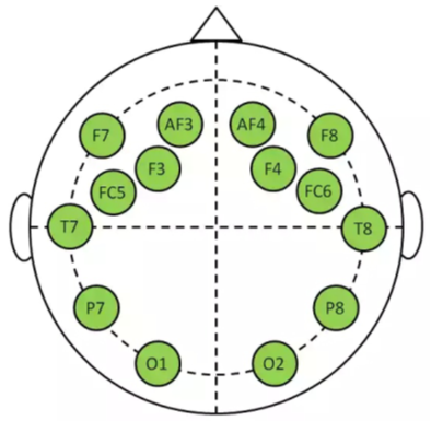 | Figure 5. Locations of the electrodes of Emotiv EPOC device [24] |
6. Procedure
- In order to reach to the final signal, we had to pass through many steps shown briefly as listed below:
6.1. Choosing the Right Channel
- The device used (Emotiv EPOC) has 14-channels only, since we can not change the main listed jobs of the channels, which impose some conditions in choosing the effective channels that are in real contact with the targeted region and in choosing the best reference electrode. Considering Figure (5) and taking into consideration the location of the motor cortex, we chose to work on the signal taken from channel (F3), since it is the best one to record the EEG signal of the motor cortex as we worked on the signal of the right hand. One of the limitations is that the Emotiv EPOC has its own file extension, which can not be loaded to MATLAB® before converting it to another form (CSV), which will prevent the online connection between the Emotiv and the PC or the Arduino.
6.2. Training the Volunteer
- In order to ensure a full domination of (α) band and reduce all the other sources of noise to its minimum values, the volunteer had been trained to sit relaxed and concentrate only on moving his right hand with the minimum effort. To do that, the volunteer has followed a prepared Power Point slide show, which has a fixed movement period and relaxation period. During the movement period, which was lasting for 1 second, the volunteer moves his right hand ONE TIME upward from his side to (90o). Then the relaxation period starts, in which the volunteer relaxs and keeps his hand lifted in position (90o), where this period was lasting for 3 seconds. The next cycle starts by another movement but in this case the volunteer will bring his hand down to rest position (beside him), as in Figure (6).
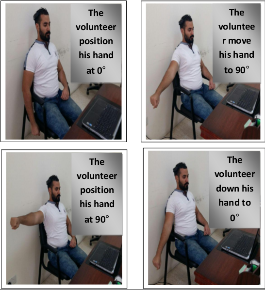 | Figure 6. The training process of the volunteer |
6.3. Processing
- After loading the data as a single matrix with14 channels we chose channel F3 and extract it from the matrix, its plot is shown in Figure (8). The obtained signal was noisy and includes a bias voltage, in order to extract the pulses out of the signal the flowchart procedure shown in Figure (7) was followed:
 | Figure 7. Procedure flow-chart |
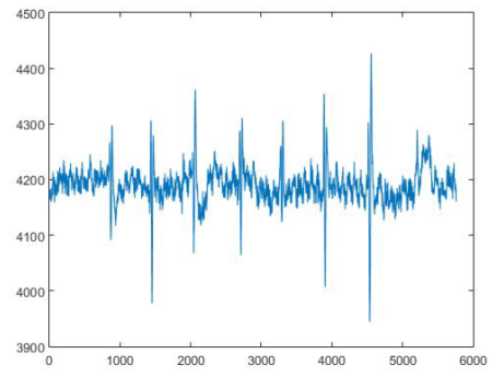 | Figure 8. The raw EEG signal of channel F3 in time domain, the x-axis represents the real time of EEG recording during right-hand movement |
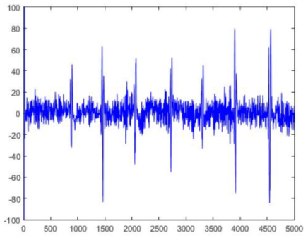 | Figure 9. The filtered EEG signal of channel F3 in time domain, the x-axis represents the real time of EEG recording during right-hand movement |
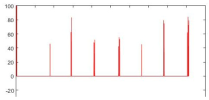 | Figure 10. The pulses extracted from the filtered F3 EEG signal, which will be fed to the Arduino micro-controller |
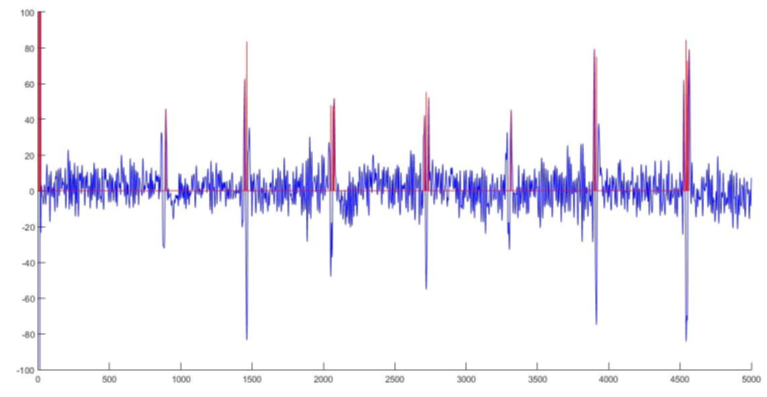 | Figure 11. A superimpose image of the original F3 EEG signal and the pulses signal |
6.4. Arduino
- Arduino is an open-source prototyping platform based on easy-to-use hardware and software [26]. Arduino is used to control the attached servo motor to make certain movements based on the orders coming directly from the MATLAB (the attached PC). Until now our work includes controlling the movement of the servo motor with a certain speed to a certain angle, these movements are direct responses to the recorded EEG signal of the movement of the volunteer right hand. The connection between the PC and Arduino micro-controller was achieved as follows:1. The ’Tower ProTM Micro Servo 9g motor, SG90’ servo motor was connected to the Arduino micro-controller through pins (5V), (GND) and D9PWM . Here we chose this type of servo motor in order to eliminate the use of external power supply, since it is small enough that can be powered by the Arduino board itself, as shown in Figure (12).2. Another wire was connected from the Arduino board (D9PWM pin) to the Servo motor input port, this wire will ensure a transmission of the movement and stop pulses between the Arduino and the servo motor.
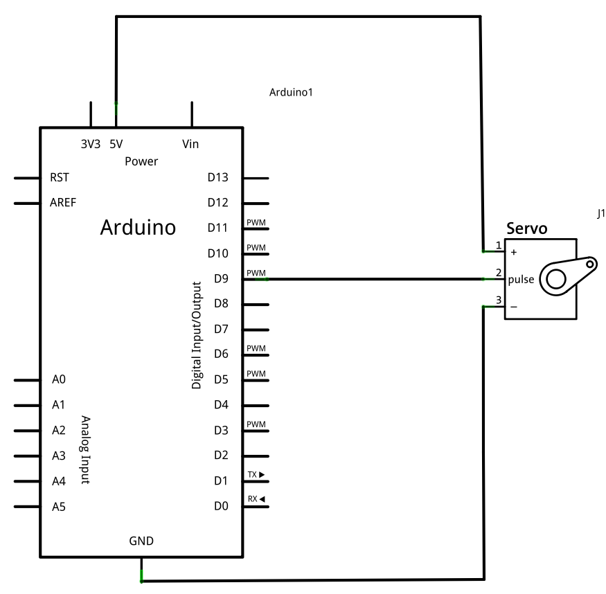 | Figure 12. A schematic of the Arduino-Servo connection map |
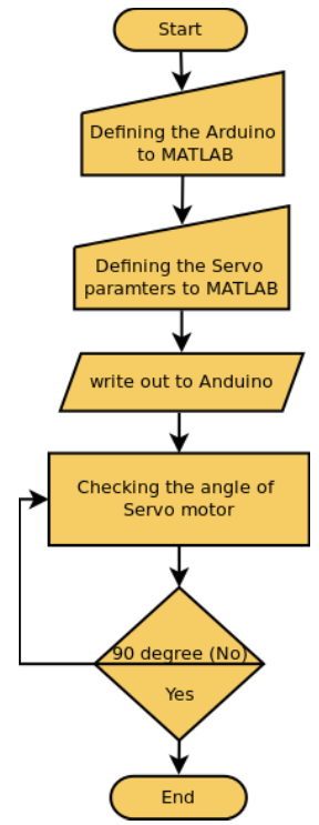 | Figure 13. Flowchart of the Servo-control circuit |
7. Conclusions
- Considering how weak is the EEG signal, the signal-to-noise ratio of the obtained EEG signal was good, which eased our work later to extract the pulses from the F3 signal. The volunteer has to be trained to sit back and relax in order to obtain this clear signal, which suggests the use of different mobile EEG recording devices if we want to go more and make this research a practical product, specially if we add the obstacles we encountered when we tried to connect the Emotiv EPOC to MATLAB, which was not possible due to that the Emotiv EPOC device was not designed to operate online in association with a PC, also the type of file used by the Emotiv EPOC to save the recorded signals is not readable by several known programming platforms such as MATLAB (also checked for Python). However, the final results were good, we managed to move the servo motor with pulse signals extracted from an EEG signal obtained from the motor cortex of a volunteer when he moved his hand.