-
Paper Information
- Paper Submission
-
Journal Information
- About This Journal
- Editorial Board
- Current Issue
- Archive
- Author Guidelines
- Contact Us
American Journal of Biomedical Engineering
p-ISSN: 2163-1050 e-ISSN: 2163-1077
2016; 6(5): 133-138
doi:10.5923/j.ajbe.20160605.01

A Computerized Numerical System to Evaluate the Effects of Skeletally Anchored Haas Palatal Expander
 Abstract
 Reference
 Full-Text PDF
 Full-text HTML
Tamer M. Nassef1, Amr E. Eldakroury2, Nagwa M. T. Mostafa3, Abou El yazeed M.3, Omnia A. Elhiny3
1Computer and Software Engineering Department, Misr University for Science and Technology, Giza, Egypt
2Orthodontcs Department, Cairo University, Cairo, Egypt
3Orthodontics and Pediatric Dentistry Department, National Research Centre, Giza, Egypt
Correspondence to: Tamer M. Nassef, Computer and Software Engineering Department, Misr University for Science and Technology, Giza, Egypt.
| Email: |  |
Copyright © 2016 Scientific & Academic Publishing. All Rights Reserved.
This work is licensed under the Creative Commons Attribution International License (CC BY).
http://creativecommons.org/licenses/by/4.0/

A three dimensional (3-D) model was generated from a Cone Beam Computed Tomography (CBCT) to evaluate the effects of skeletally anchored Haas palatal expander using finite element analysis, where the results present a high resolution 3-D model was obtained from the CBCT and revealed that low to moderate stress was obtained from the appliance with no stress concentration around the mini-screws. The study concluded that the appliance is a viable treatment option that produced stresses within the physiological limits.
Keywords: Maxillary expansion, CBCT, Finite Element Analysis, Dental Modeling
Cite this paper: Tamer M. Nassef, Amr E. Eldakroury, Nagwa M. T. Mostafa, Abou El yazeed M., Omnia A. Elhiny, A Computerized Numerical System to Evaluate the Effects of Skeletally Anchored Haas Palatal Expander, American Journal of Biomedical Engineering, Vol. 6 No. 5, 2016, pp. 133-138. doi: 10.5923/j.ajbe.20160605.01.
Article Outline
1. Introduction
- Among the most remarkable aspects of palatal expansion is the predictability of the results following treatment [1]. Transverse dimension problems are dealt with usually by maxillary expansion through opening the mid-palatal suture by appropriate appliances. For an ideal maxillary expansion appliance, maximum skeletal and minimal dental effects are required. Unfortunately, most of the studies in the literature have concluded that the effects of maxillary expansion appliances are mostly dental in nature. The dento-alveolar effects are produced by the way the appliance is anchored. Haas stated that (The primary law of orthopaedics is “thou shalt utilize maximum anchorage to gain your orthopaedic objectives” [2]) but the dento-alveolar effect was unavoidable with the conventional appliance.Recently, with the introduction of mini-implants a paradigm shift has occurred at the anchorage perspective. Conventional treatment mechanics have been enhanced by refining them with the use of mini-implants. As happening with every innovation, the learning curve is steep. Choosing the best way the mini-implant can enhance a certain treatment methodology needs a lot of trials and comparisons. Combining a traditional expansion appliance with mini- implant is one of these trials aiming to produce the desired maximal skeletal effect and a minimal dental one.Finite element analysis is a numerical analysis method used to predict the effect of stresses on complex geometrical structures. There are broadly two types of application in biomechanical studies. The first is the analysis of stress and strain with a given force system that is applied to the teeth or the cranial complex. The second is the evaluation of the craniofacial growth with the given skeletal displacement observed during the growth changes [3]. Angel proposed the procedures of palatal expansion and it was consolidated clinically by Haas [1, 4].The main Target of palatal expansion is the coordination of the mandibular and maxillary denture bases. The appliance should be designed to enhance the orthopedic movement and to decrease the orthodontic response.El Dakroury et al [5], 2003, conducted a study to analyze the voice parameters of patients after rapid maxillary expansion using orthopaedic appliances or surgically assisted rapid maxillary expansion. They concluded that the encountered changes in voice parameters between the two groups are mainly due to different dental, muscular and skeletal responses in the two expansion procedures.Ghoniem [6], 2011, conducted a study to evaluate the effect of skeletally anchored Haas type expander three dimensionally, in order to determine and differentiate the amount of expansion at the skeletal level and dental level. The results showed that skeletal expansion occurred with a percentage of 64.2%, 57.1%, and 54.9% at the areas of canine, premolar and molar respectively from the amount of expansion at the level of jack screw. Changes in the premolars angulations were insignificant while molars angulation showed significant change that indicated a tendency toward buccal movement with buccal root torque. He concluded that skeletally anchored Haas type expander is an effective method for expansion and that the appliance produced more skeletal effects than dental. Mosleh et al [7], 2015, compared and evaluated the dentoskeletal effects of tooth-borne and 4-point bone-borne rapid maxillary expanders in growing children. They found that basal bone expansion at the level of the hard palate was produced by both expanders, more dental expansion, buccal rolling, and a greater increase in nasal width was produced by the tooth borne maxillary expanders, than did the bone borne maxillary expanders. It should be mentioned that the basis for modem finite element stress analysis was set down by Robert Hooke in 1678. It was firstly used in aerospace industry in the late sixties and in the early seventies it was applied in dentistry [8].Boryor A. et al [9], 2010, used fresh and dried fixed human skulls to investigate the effects of high maxillary expansion forces on the skull. Only in one experiment the maxillary suture was not weakened. They also compared the strain measured on the zygomatic process of the skull with the results of a finite element model generated for this purpose. Increasing transversal force was applied on the alveolar process (teeth) until rupture. Maxilla displacement, the expanding forces and strain on the zygomatic process, were registered. They found that, during the experiments and FE simulation; the highest stress was observed on the alveolar process. They concluded that, the existence of appropriate models is important and that female specimens seem to rupture at a lower force than male ones. Specimens of both genders show a similar linear behavior in the force/strain curve within each gender group. There is a very low probability for opening of maxillary suture in adults during ultra-rapid maxillary expansion with tooth anchorage, also; complications and unwanted rupture could occur.Cone beam computed tomography (CBCT) was presented by Mozzo et al [10] in 1998 as a new type of volumetric computed tomography. They evaluated radiation dose and accuracy of measurements and they concluded that this new system (CBCT) is very promising due to the good performances and low cost together with low radiation dose, which is interesting in view of large-scale use of the CT technique in such diagnostic application. Nassef et al [11-13] used the output of CT files to generate a 3-D finite element models and they conclude that Many clinicians find that the benefits of using CT in follow up outweighs the risks of increased radiation doses especially with modified scanners of lower radiation doses. EI-Beialy et al [14], 2011, evaluated two methods of virtual 3-D skull the reliability and accuracy of different head orientations using three-dimensional CBCT scans. Twelve and eleven linear measurements respectively in the first and second methods, twelve distances were compared on the physical skull and the 3-D virtual skull in the centered and the other scanning positions in the first method, while in the second method, coordinates of 11 landmarks were identified in 5 different scanning positions. High concordance was seen between the CBCT centered-position measurements and the skull. Also a very high concordance was found between measurements of the centered relation to those from the different skull positions. They concluded that changing the skull orientation did not affect the accuracy and reliability of CBCT measurements.
2. Construction of the Model
- The selected patient was a male to benefit from the delayed longer maturation range compared to females, where their permanent dentition could be relatively completed while a considerable amount of skeletal growth remains [15].The appliance is different from previously studied bone-borne appliances in corporation acrylic plates which provided a wider area for force application and a higher level of force near the center of resistance of each maxillary bone which is located superior and lateral to the distal root of the upper first molar [16]. Since the force is applied near or at the center of resistance, less or no moments are created. This moment is responsible for the dentoalveolar buccal rolling [17].Nowadays CBCT gained more popularity [18], the advantages of this technology are fairly low cost, convenient machine size, 3D images of dentofacial regions, ease of operation, relatively quick scans and low radiation exposure as compared to traditional computed tomography [19-23].During scanning, while the patient was closing in maximum intercuspation position, the cusps of upper and lower teeth intermingled in axial slices and it was hard to differentiate the end of a tooth and the beginning of the other, thus; the patient was asked to wear a splint made of thermoplastic material of 2 mm thickness.I-CAT 3D cone beam imaging machine was used and DICOM files were exported to MIMICS software where image analysis was done by cropping the maxillary jaw with the full set of maxillary teeth, then segmentation mask was created by thresholding, were. Different tissues in the region of interest were identified through the selection of a range of grey values (Hounsfield unit).Hounsfield unit (HU) is defined as:
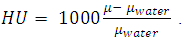 | (1) |
|
3. Results and Discussion
- After running the analysis the results were collected, the results of interest were:- Modelling- Stress distribution
3.1. Three Dimensional (3-D) Modelling
- A Model with high resolution and small topographic details was obtained from the CBCT as shown in Figures 1, 2.
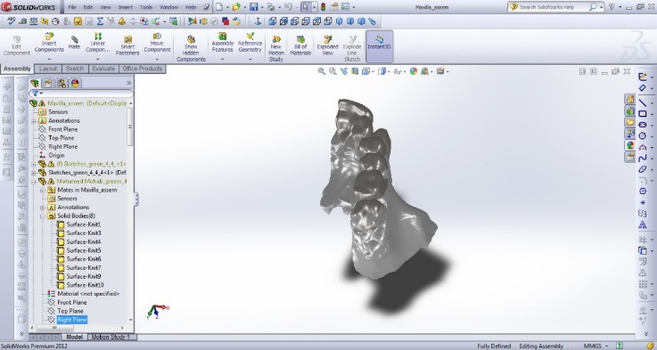 | Figure 1. One half of the Maxilla |
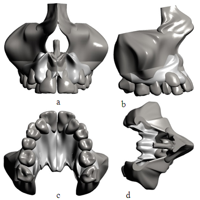 | Figure 2. Mirrored Maxilla; (a) Frontal view, (b) Lateral view; (c) Palatal view, (d) Top view |
3.2. Stress Distribution
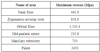
- The results showed that collective stresses were all types of stresses occurred at each area at the same time so only Von Mises stress “equivalent stress” was calculated; Figures 3, 4.Mild to moderate stresses were produced by the appliance and there was no increase in stresses around mini-screws.
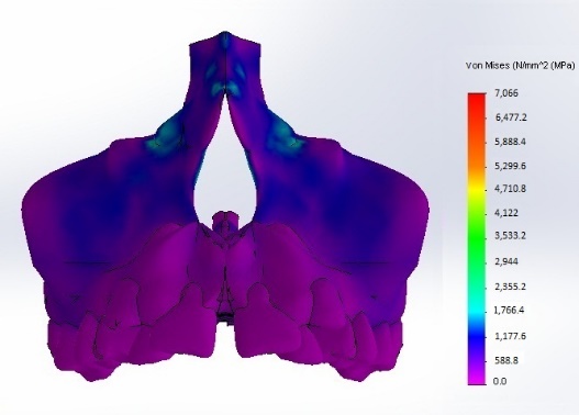 | Figure 3. Stress distribution; Frontal view |
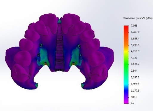 | Figure 4. Stress distribution; Palatal view |
4. Conclusions
- The skeletally anchored Haas palatal expander is a viable treatment option, where the results of the computerized numerical system showed no areas of high stress concentrations as they were distributed along a larger surface area by the acrylic pads and the mini-screws served mainly as an anchor. The application of the load must be at or as near as possible to the center of resistance of the maxilla and to achieve bone stress relaxation; the increasing relaxation time between two successive activations of the jackscrew is necessary. The limitations of this study involved several approximations in the material properties of the tissues. Since the material properties of the teeth do not affect the results significantly, all bony tissues were given the mechanical properties of cancellous bone and all teeth were given the properties of dentin. The finite element models did not include the whole skull, so the results represent only the response of that part of the craniofacial structure. Elements representing tissues were considered isotropic and solved with linear- elastic properties. It is not based on the individual skull geometry of each patient and it does not consider the different elastic modules of sutures during growth.