-
Paper Information
- Paper Submission
-
Journal Information
- About This Journal
- Editorial Board
- Current Issue
- Archive
- Author Guidelines
- Contact Us
American Journal of Biomedical Engineering
p-ISSN: 2163-1050 e-ISSN: 2163-1077
2016; 6(4): 124-131
doi:10.5923/j.ajbe.20160604.03

Analysis of Radiation Transport through Multileaf Collimators Using BEAMnrc Code
 Abstract
 Reference
 Full-Text PDF
 Full-text HTML
Ankit Kajaria1, Neeraj Sharma1, Shiru Sharma1, Satyajit Pradhan2, Abhijit Mandal2, Lalit. M. Aggarwal2
1School of Biomedical Engineering, Indian Institute of Technology (BHU) Varanasi, UP, India
2Department of Radiotherapy and Radiation Medicine, Institute of Medical Science (BHU) Varanasi UP, India
Correspondence to: Ankit Kajaria, School of Biomedical Engineering, Indian Institute of Technology (BHU) Varanasi, UP, India.
| Email: |  |
Copyright © 2016 Scientific & Academic Publishing. All Rights Reserved.
This work is licensed under the Creative Commons Attribution International License (CC BY).
http://creativecommons.org/licenses/by/4.0/

In this study, the BEAMnrc Monte Carlo code is used to investigate the characteristics of radiation transported through multileaf collimators (MLC) for 6 MV photon beam produced by Varian linear accelerator. We have used Monte Carlo simulation model to calculate radiation leakage as a function of field size for Varian 120-leaf MLC by accurate modelling of the complex geometry of MLC. We also calculated the effect of MLC on percentage depth dose characteristics, photon spectra and photon average energy distributions. A significant increase in MLC leakage with increase in field size has been observed in our study. Photon spectra and photon average energy distributions are found to be substantially modified by MLC as it removes lower-energy photons resulting in increase of PDDs for MLC blocked fields in comparison to the jaw define open fields. In our study, we have also calculated surface dose and electron fluence spectra for MLC and jaw define fields. Clear increments in surface dose and electron fluence spectra for MLC define fields have been observed. These results suggest that use of MLC to define treatment field increases surface dose.
Keywords: Monte Carlo simulation, Multileaf collimator
Cite this paper: Ankit Kajaria, Neeraj Sharma, Shiru Sharma, Satyajit Pradhan, Abhijit Mandal, Lalit. M. Aggarwal, Analysis of Radiation Transport through Multileaf Collimators Using BEAMnrc Code, American Journal of Biomedical Engineering, Vol. 6 No. 4, 2016, pp. 124-131. doi: 10.5923/j.ajbe.20160604.03.
Article Outline
1. Introduction
- The planning aspects of intensity modulated radiation therapy (IMRT) treatment delivery rely on the use of multileaf collimators (MLC) to produce desired intensity pattern. The dose distributions for a given complex intensity pattern are very sensitive to detailed structure of MLC. To treat the desire section of a treatment field rest portion is blocked by MLC in an IMRT treatment. In these blocked segments significant portion of dose can be delivered due to radiation leakage from MLC. The contribution of MLC leakage to a point in an IMRT field can be calculated by the static field leakage multiplied by the product of the number of monitor units delivered for the IMRT field and the fraction of time the point is blocked by the MLC. In dynamic IMRT treatment large numbers of monitor units are used due to which the MLC leakage can exceed above 10% of the maximum in field dose [1]. Previously in a Monte Carlo (MC) study an increase in MLC leakage with increase in field size was reported by Kim et al. [2]. These radiation leakages from MLC must be consider in dose calculation to avoid dosimetric errors. The Monte Carlo methods have been used extensively to estimate accurate dose distributions for clinical beams. Several studies have been conducted using these methods for analyzing influence of linac head components on beam characteristics [3-5]. Studies describing the beam hardening effect of flattening filter on photon energy spectra, absorbed dose and beam profiles have also been published [6]. Therefore Monte Carlo simulation model can be used to accurately calculate the effect of MLC on dose distributions for a typical modern accelerator such as Varian Clinic 600 unique performance. Our study reports on variation of radiation leakage from MLC as a function of field size for 120- leaf Varian MillenniumTM Multileaf Collimator. We also calculated the effect of MLC on percentage depth dose characteristics, photon spectra and photon average energy distributions. The effect of using MLC to define treatment field on surface dose and electron fluence spectra have also being evaluated in our study.
2. Material and Methods
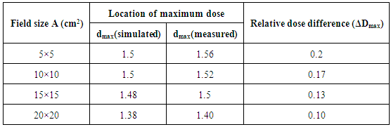
- Simulation model of Varian Clinic 600 unique performance was developed using Monte Carlo code system BEAMnrc [7, 8] in our study. To derive the best estimates for the mean energy and full width at half maximum (FWHM) of the electron beam incident on the target, Monte Carlo simulations for monoenergetic beams ranging from 5.5 to 6.2 MeV with FWHM varied from 0.15 to 0.25 cm were performed to find the best match with percentage depth dose (PDD) and profiles measurements. A monoenergetic source with kinetic energy of the beam 5.7 MeV and FWHM for the X and Y directions of 0.2 cm was found to give best agreement with measured data. Geometry and materials used to build the Monte Carlo simulation model of the linear accelerator were based on machine specifications as provided by the manufacturer Varian Medical Systems. The linac was structured in the following order: a target slab of tungsten and copper, primary collimator (tungsten), flattening filter, ion chamber, mirror, jaws (tungsten) and finally the option for 120- leaf Varian MillenniumTM Multileaf Collimator. To model the geometry of 120-leaf Varian MillenniumTM Multileaf Collimator special geometry package of BEAMnrc was used. The 120-leaf MLC consists of two banks of 60 leaves each. The 40 central leaves produce a 0.5 cm resolution at 100 cm source to surface distance (SSD) and the 20 outer leaves produce a 1.0 cm resolution at 100 cm SSD. All details of the leaf design were included in the Monte Carlo geometry, including the tongue-and-groove used to reduce radiation leakage through interfaces between adjacent leaves and the complex rounded leaf tip. All materials used in the Monte Carlo (MC) simulation were extracted from the 700 ICRU PEGS4 (pre-processor for Electron Gamma Shower) cross section data available in BEAMnrc, and met the specifications for the linac as provided by the manufacturer. Different stages of simulation and component module used to model various component of 6 MV photon beam produced by Varian Linac using principal features of BEAMnrc-DOSXYZnrc code [9, 10] are shown in figure 1. In the simulation of the full accelerator unit we have split the calculation into three steps in order to save time. In the first step, which takes the most computing time, 1.5×10⁸ initial histories are initiated and a monoenergetic electron beam source of kinetic energy of 5.7 MeV with FWHM for the X and Y directions of 0.2 cm was incident on the target. The primary collimator, flattening filter and ion chamber are included in this step. The output of this step is a phase space file at plain one as show in figure 1, having information of energy, position, direction, charge and history variable for every particle exiting downstream from the end of ion chamber. Since the source and primary collimator have fixed openings, it is possible to use this phase space data for the simulation of different field sizes. This large set of particles produced in first step is used repeatedly as the input to the next step of simulation. The second step of the calculation simulates the passage of the particles through the mirror; adjustable collimators, MLC and air slab to a plane at SSD 100 cm from target. We simulate different openings of jaw as well as MLC to get field sizes from 5×5 to 20×20 cm2 at an SSD equal to 100 cm. For the latter case in MLC define field sizes the projected jaw setting was 5 cm larger than that of MLC. In addition for MLC leakage calculations, MLC leaves were configured to fully block the open field produced by the jaw with the leaves of MLC were positioned asymmetrically with respect to the central axis. The output of this step is a phase space file at plain two as show in figure 1, having information of energy, position, direction, charge and history variable for every particle reaching the plain at SSD 100 cm from target. The data analysis program BEAMDP [11] was used to analyze the phase space data files to extract the various types of spectra of all particles reaching the plane at SSD 100 cm. The effect of MLC on photon beam characteristics was determined by calculating and comparing the photon spectra on central axis and average energy distributions at 100 cm SSD for a jaw-defined open field and the same field blocked by the MLC for various field sizes. Photon interactions within the MLC can generate secondary electrons that can contribute dose to a patient. To determine the relative dose contributions from these secondary electrons, electron spectra for MLC define and jaw define field size were also calculated in our study. In the third step of simulation, the phase space files for field sizes of 5×5 to 20×20 cm2 at an SSD of 100 cm which were obtain at end of second step are reused by the DOSXYZnrc code as an input for dose calculations in a water phantom as shown in figure 1. We transport the particles through a water phantom of dimension 30×30×30 cm3 with voxels size of 0.25×0.25×0.25 cm3. A comprehensive set of measured dosimetric data for 6 MV photon beams where acquired using a three-dimensional (3D) phantom, Blue phontom2 IBA Dosimetry GmbH and OmniPro-Accept 7 data acquisition software. All the measurements were performed with a Scanditronix/ Wellhofer compact ionization chamber CC13, in the water phantom. In order to validate our simulation model depth-dose curves for 6MV photon beam for field size 5×5 to 20×20 cm2 were calculated in an on axis cylinder of radius 1 cm using Monte Carlo simulation and compare with measured data. The calculated central axis depth-dose curves were normalized to unity at the depth, dmax, of the maximum dose deposition, Dmax. Both results measured and calculated, could then be compared with respect to the relative value of the maximum dose Dmax and the corresponding depth dmax. Figure 2 show the comparison between the calculated depth-dose distributions and measurements for 10×10 cm2 field size studied in this work. The comparison shows that the calculated and measured data agree within 1% of local relative dose, and 1 mm in depth at all depths and field sizes which are summarized in table 1. This simulation model was thereafter used to calculate percentage depth dose curves (PDDs) for MLC blocked field which were compared with PDDs of jaw define open field to illustrate the effect of MLC on depth dose characteristics. In addition the surface dose were evaluated and compared for jaw and MLC define fields in our study.
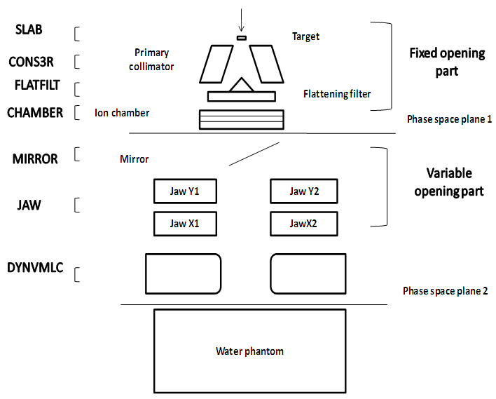 | Figure 1. 6 MV Varian Linac simulation model separated into three parts: (a) Treatment head fixed and variable opening part representing first, (b) second step of simulation modelled using component module of BEAMnrc code and (c) Dose Calculation inside water phantom using DOSXYZnrc code in third step |
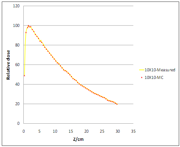 | Figure 2. A comparison of measured and calculated depth doses curves of the 6MV photon beam for field size of  |
|
3. Results
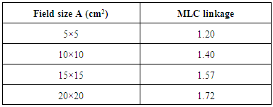
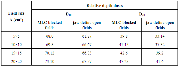
- MLC linkage: MLC leakage is an important parameter needed for the commissioning of a treatment-planning system. We have calculated the MLC leakage as a function of field size in our study and are presented in table 2. MLC leakage represents the dose on the central beam axis with MLC blocked fields normalized by the dose of jaw define open fields of the same field size at 1.5 cm depth for SSD 100 cm. Jaw defined open field taken as the MLC leaves, are withdrawn underneath the jaws so that to not intercept the beam, where the field size is defined by the treatment jaws only. MLC blocked fields define a field in which the MLC leaves are configured to fully block the open field produced by the jaw. To ensure that the jaws blocked the rounded tips of the leaves completely in MLC blocked fields, the leaves of MLC were positioned asymmetrically with respect to the central axis and their projected offset at 8.0 cm of isocenter.
|
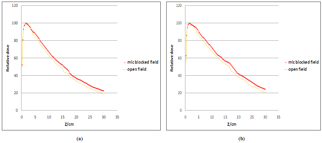 | Figure 3. Comparison of relative depth dose curves calculated for MLC blocked and jaw define open fields for 6MV photon beams for field sizes: (a)  (b) (b)  |
4. Analysis of Spectra
- The analysis has been made in four parts:(i) Photon fluences spectra Figure 4 shows central axis photon spectra as a function of energy (number of photons per MeV per incident electron on the target) for both MLC blocked and jaw define open fields for 20×20 cm2 field size. Photon originated in target passes through the collimating system on their way to the scoring plain at an SSD 100 cm. Scoring plain is an annular region around the central axis with radius 0 < r < 2.25 cm. The range of possible energy of photon is divided into interval (bin) of 0.25 MeV. The number of photon within each energy bin crossing the scoring plain is being recorded separately for both MLC blocked and jaw define open fields. In figure 4 for comparison, the fluence plots are normalized in such a way that total area under each curve equals one. The precision of calculated central-axis photon spectra is high and uncertainty in each 0.25 MeV wide bin is usually between 1 to 5%, except for the high-energy end of the spectra. It was observed from figure 4 that for MLC blocked field the fluence of photon were having more high energy photons in comparison to the jaw define open field. Our results are in agreement with the results reported by Kim et al. [2] in which they coated an harder photon spectra for MLC blocked field in comparison to open field.
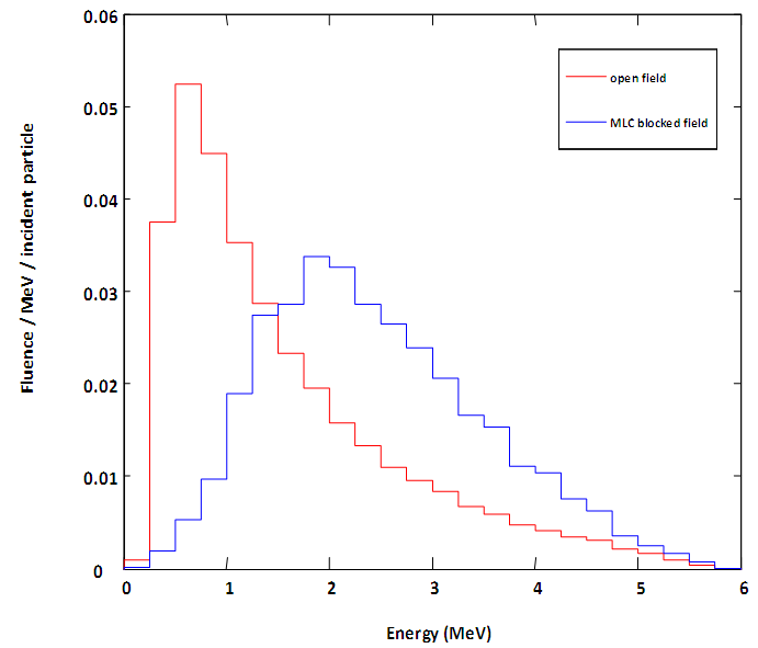 | Figure 4. Photon fluences per initial electron on the target, at the top of the water phantom as a function of energy (MeV) for field size  |
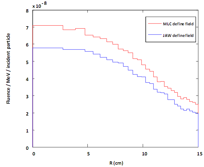
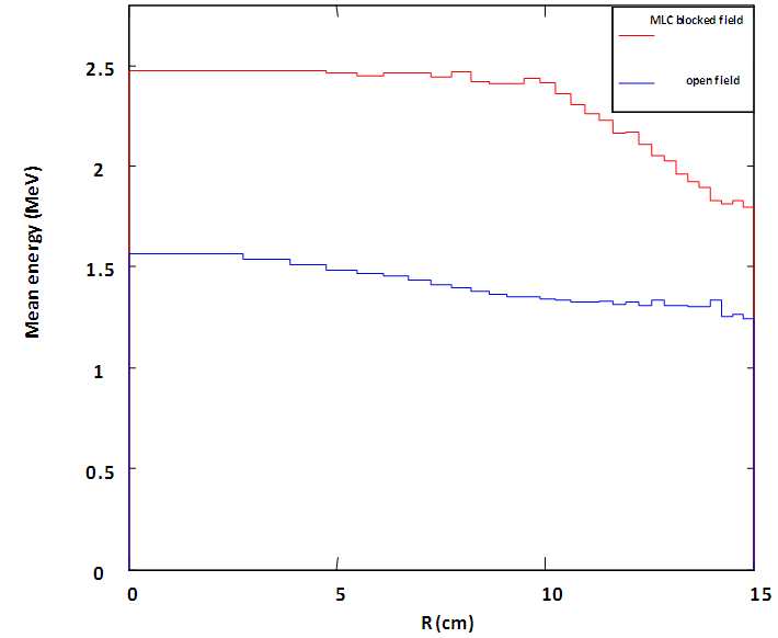 | Figure 5. Photon average energy distribution of the MLC blocked and jaw define open fields as a function of off axis distance for field size of  and SSD of 100 cm and SSD of 100 cm |
 | Figure 6. Electron fluences per initial electron on target, at the top of the water phantom as a Function of off axis distance for  field size calculated for both MLC and Jaw define field field size calculated for both MLC and Jaw define field |
|
5. Discussion
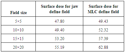
- Our study showed an agreement in MC calculated and measured depth-dose data within 1% of local dose, and 1 mm in depth at all depths and field size which give satisfactory validation of our simulation model for 6 MV photon beam. Thereafter we used this simulation model to calculate MLC leakage as a function of field size. It was observed that the calculated MLC leakage value increases with increase in field size. Our results are in agreement with the results reported by Kim et al. [2] in which they reported an increase in MLC leakage value with increase in field size. The calculated PDDs for MLC blocked field showed slightly higher values in comparison to the jaw define open beam for all field sizes. Differences in the PDDs between the two cases were found to increase with depth for all field sizes. In our study we calculated average energy distribution of photon as a function of off axis distance and central axis photon fluence spectra as a function of energy for both MLC blocked and jaw define open fields for 20×20 cm2 field size. Significant increase in average energy on central axis was observed for MLC blocked field in comparison to jaw define open field. This increment in average energy is due to the removal of low energy photons by MLC which also affects the on axis photon spectra as for MLC blocked field it contains more high energy photons in comparison to the jaw define open field. In our study we calculated surface dose for both MLC and jaw define fields. Clear increment in surface dose for MLC define fields was observed. These results were further verified with the calculation of electron fluence spectra as a function of off axis distance for 20×20 cm2 field size at 100 cm SSD for both MLC and jaw define fields. Considerable increase in electron fluence was observed for MLC define fields in comparison to jaw define fields. The possible explanation for this increment is that the use of MLC to define treatment field increases the photon interactions within the MLC which causes generation of secondary electrons. These low energy electrons contribute to surface dose.
6. Conclusions
- A Monte Carlo simulation model of 6 MV photon beam from Varian Clinic 600 unique performance accelerator has been developed and benchmarked against measurements. We have performed Monte Carlo simulations to study the properties of radiation transport through multileaf collimators. The results of our study showed that MLC leakage increases with increase in field size. The MLC substantially modified the photon energy spectrum by removing lower-energy photons resulting in rise of PDDs of MLC blocked fields in comparison to the jaw define open fields for all field sizes. The use of MLC to define treatment field increases surface dose due to increases in electrons.
References
| [1] | Mohan, R., Arnfield, M., Tong, S., Wu, Q., & Siebers, J. (2000). The impact of fluctuations in intensity patterns on the number of monitor units and the quality and accuracy of intensity modulated radiotherapy. Medical physics, 27(6), 1226-1237. |
| [2] | Kim, J. O., Siebers, J. V., Keall, P. J., Arnfield, M. R., & Mohan, R. (2001). A Monte Carlo study of radiation transport through multileaf collimators. Medical physics, 28(12), 2497-2506. |
| [3] | Verhaegen, F., & Seuntjens, J. (2003). Monte Carlo modelling of external radiotherapy photon beams. Physics in medicine and biology, 48(21), R107. |
| [4] | Sheikh-Bagheri, D., & Rogers, D. W. O. (2002). Monte Carlo calculation of nine megavoltage photon beam spectra using the BEAM code. Medical physics, 29(3), 391-402. |
| [5] | Mesbahi, A., Reilly, A. J., & Thwaites, D. I. (2006). Development and commissioning of a Monte Carlo photon beam model for Varian Clinac 2100EX linear accelerator. Applied radiation and isotopes, 64(6), 656-662. |
| [6] | Lee, P. C. (1997). Monte Carlo simulations of the differential beam hardening effect of a flattening filter on a therapeutic x-ray beam. Medical physics, 24(9), 1485-1489. |
| [7] | Rogers, D. W. O., Faddegon, B. A., Ding, G. X., Ma, C. M., We, J., & Mackie, T. R. (1995). BEAM: a Monte Carlo code to simulate radiotherapy treatment units. Medical physics, 22(5), 503-524. |
| [8] | Rogers, D. W. O., Walters, B., & Kawrakow, I. (2001). BEAMnrc users manual. NRC Report PIRS, 509. |
| [9] | Kawrakow, I., & Walters, B. R. B. (2006). Efficient photon beam dose calculations using DOSXYZnrc with BEAMnrc. Medical physics, 33(8), 3046-3056. |
| [10] | Walters, B., Kawrakow, I., & Rogers, D. W. O. (2005). DOSXYZnrc users manual. NRC Report PIRS, 794. |
| [11] | Ma, C. M., & Rogers, D. W. O. (1995). BEAMDP users manual. NRC Report PIRS-0509 (D). |