-
Paper Information
- Previous Paper
- Paper Submission
-
Journal Information
- About This Journal
- Editorial Board
- Current Issue
- Archive
- Author Guidelines
- Contact Us
American Journal of Biomedical Engineering
p-ISSN: 2163-1050 e-ISSN: 2163-1077
2016; 6(1): 19-24
doi:10.5923/j.ajbe.20160601.03

Novel Twin Screw Co-Extrusion-Electrospinning Apparatus
 Abstract
 Reference
 Full-Text PDF
 Full-text HTML
Raúl Montiel1, Rosalba Patiño-Herrera2, J. A. Gonzalez-Calderón3, Elías Pérez4
1Área de Polímeros, Depto. de Física, DCBI, Universidad Autónoma Metropolitana-Iztapalapa, Vicentina, México
2Departamento de Ingeniería Química, Instituto Tecnológico de Celaya, Guanajuato, Mexico
3Departamento de Ingeniería Ambiental, Instituto Tecnológico de Celaya, Guanajuato, Mexico
4Instituto de Física, UASLP, San Luis Potosí, México
Correspondence to: Raúl Montiel, Área de Polímeros, Depto. de Física, DCBI, Universidad Autónoma Metropolitana-Iztapalapa, Vicentina, México.
| Email: |  |
Copyright © 2016 Scientific & Academic Publishing. All Rights Reserved.
This work is licensed under the Creative Commons Attribution International License (CC BY).
http://creativecommons.org/licenses/by/4.0/

The present work presents the design and construction of a device that allows for the continuous processing of a scaffold based on three interconnected steps: 1) melting for extrusion; 2) electrospinning for achieving nanoscale fibers and finally 3) exposure to UV radiation for reaching proper fiber crosslinking. All necessary for fabricating crosslinked networks or meshes with important applications in biomedicine.The suggested design, based on twin screw extrusion, meets the conventional methods of plastic extrusion at different temperatures and different loading and feeding speeds. This novel design includes a secondary feed port to incorporate other plastics, additives, or plasticizers. Therefore, it can be used like a co-extruder. In addition, by applying high voltage to the isolated output capillary, the device can act as an electro-spinning machine. This allows for obtaining a graduated ´layer by layer´ scaffolding generation, including phase separation during the melting process, which permits the production of scaffolds of a wide range of compositions, porosity and mechanical properties.
Keywords: Design, Twin screw extrusion, Electrospinning
Cite this paper: Raúl Montiel, Rosalba Patiño-Herrera, J. A. Gonzalez-Calderón, Elías Pérez, Novel Twin Screw Co-Extrusion-Electrospinning Apparatus, American Journal of Biomedical Engineering, Vol. 6 No. 1, 2016, pp. 19-24. doi: 10.5923/j.ajbe.20160601.03.
Article Outline
1. Introduction
- Twin extruders, produce a thrust much greater that of a single screw, providing higher accelerations as well as shear stress of greater intensity. Twin screw extruders may be found rotating in the same direction (co-rotating), and in opposite directions (counter-rotating). According to the thrust or flow, the twin screw extruders are counter-rotating when the flight depth of first one does not penetrate into the corresponding flight depths of the second one, see Figure 1(a), and have little dependence on the viscosity of the load, Figure 1(b). In this type of extruder, the materials tend to move the screws towards the barrel wall and therefore cannot generate speeds high enough to be adequately mixed.
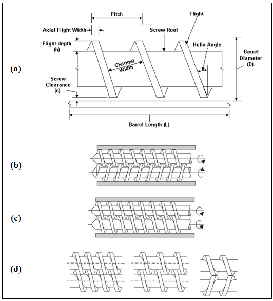 | Figure 1. (a) twin screw parameters, (b) counter-rotating, (c) co-rotating and (d) interpenetration degree |
 According to Mani et al [1], an acceptable approximation for the flow rate is:
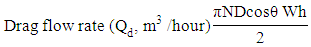 N is screw speed (revolutions per hour), D is diameter of screw (m), θ is flight angle, W is width of screw (m) and H is flight depth (m), see Figure 1 and 6.This design allows the scaffolding graduates generation layer by layer including phase separation in the melt [2, 3]. Another option suggested by Leong, K, 2008 [2], used in bone tissue engineering, is based upon the use of porous polymeric scaffolds seeded with one individuals own stem cells. This approach promotes tissue constructs based upon cells´ proliferation and differentiation on a scaffold within a bioreactor which are then implanted in the injured area.Common polymeric materials used in tissue engineering scaffolds are polyglycolic acid, polylactide, polycaprolactone (PCL) and its copolymers or their bio-particles, such as hydroxyapatite and tricalcium phosphate, as well as other growth factors bio agent and some proteins [4, 5, 6-10]. From bio-resorbable polymers, osteo-conductive and additives extrusion technology twin screws can be applied to manufacture implants and scaffolds for the regeneration and repair of bone tissue. In this twin screw co-extrusion technology (TSE), it includes a head electrospinning device. Normally, for making graded structures, PCL and PGS-PCL biocomposites with high availability and tricalcium phosphate particles (TCP) and PCL is used. This study's results suggest that PGS elastomer is an auspicious osteoconductive material for the regeneration of bony defects. These results can be an innovative reassessment of the current art of selection for novel bone scaffold materials.This twin screw co-extruder has the versatility to make electrospinning and co- electrospinning for developing new production processes more viable to use in scaffold for tissue engineering in the regeneration of both bone and soft tissue. This design will be able to scale the size and distribution of porosity scaffolds varying continuously, by adding bioactive agents and other components. As an example scaffolds with interconnected porosity from polycaprolactone, incorporating different concentrations and particle size distribution of β-hydroxiapatita and tricalcium phosphate can be produced to increase the conductivity; with the possibility of additional bioactive agents for cell proliferation and differentiation [13-15].In addition to controlling the mechanical properties in both directions: radial and axial, potentially allowing the best imitation of the natural complexity of native tissues, might even be suitable for the repair of critical size bone defects and fusion for spinal applications. Despite advances in tissue engineering, none of these methodologies is flexible enough to allow industrially scalable and reproducible classification of bone graft substitutes and scaffolding for a wide range of compositions, porosity and specific mechanical properties.
2. Apparatus Description
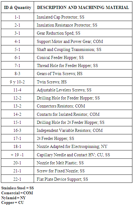
- The Twin co-extruder consists of a stainless steel cylinder block which at its center has two cylindrical bores next to one another to allow the placement of two screws with chord pitch equal to the length of the screws which rotate in the same direction, to drag and compress a polymer melt, forcing it out for an small extrusion die or capillary nozzle. In Figure 2, an assembly drawing of the main parts is shown. The co-extruder has a secondary feed port for adding others polymers, additives and plasticizers, the co-extruder die can be replaced by a capillary nozzle or needle to fabricate scaffolds by electrospinning. The device has independent variable resistors for controlled heating, according to the temperature profile of engineering plastics fed on the main port or hopper at the opposite of the output die. The twin screw extrusion system is controlled by tree coupled gears and a servo motor whose speed control is mounted on a small console along with other registry systems and temperature control.In Figure 2 and Table 1, the identification numbers (ID), the quantity of these (ITEMS), description and material machining are listed.
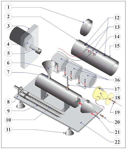 | Figure 2. Identification of main parts of the extruder |
|
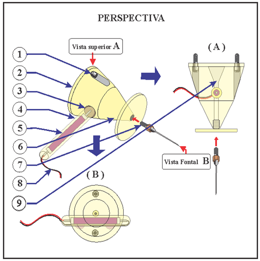 | Figure 3. Drawing of the parts of the nozzle electrospinning |
|
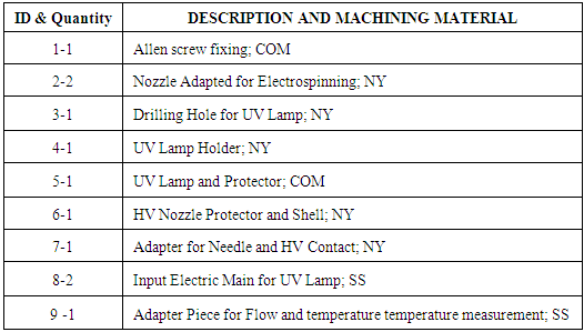
 | Figure 4. A drawing showing the extruder from a lateral view |
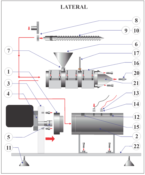
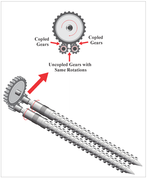 | Figure 5. Shows the engagement of the gears and twin screw to obtain the same rotation at the screws, i.e., co-rotating |
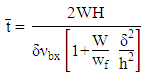 The dimensionless time as given by:
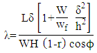 Were r is the throttle ratio and L the effective length of screw.
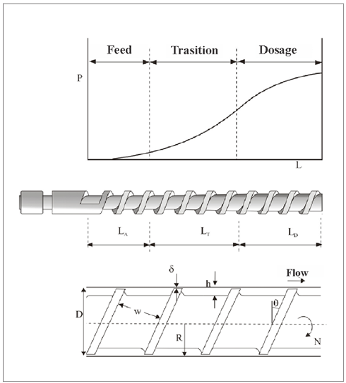 | Figure 6. Sections and parameters of the screw |
 helix angle, W channel width, h channel depth, d clearance between the cylinder and the fillet, wf flight width (see Figure 1).
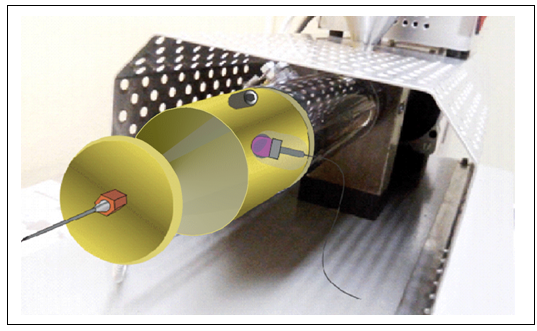 | Figure 7. Displaying the electrospinning accessory coupled to the extruder |
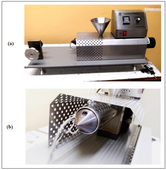 | Figure 8. (a) Photography in side view, (b) Photography in 25 ° front view |
3. Results and Calibration
- Several tests were made in engineering plastics, in which the melting temperature and mixing speeds were calibrated. In the Figure 9, shows a photograph of polypropylene films obtained with several loads of titanium oxides (TiO2), Silicon and Alumina. These films were annealed to relieve the stresses in the extrusion. Small parts of these films were cut for the purpose of their characterization by means of X-ray, DSC, IR, etc.
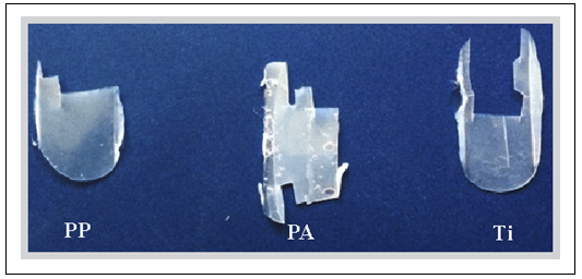 | Figure 9. Extruded polypropylene films with TiO2 |
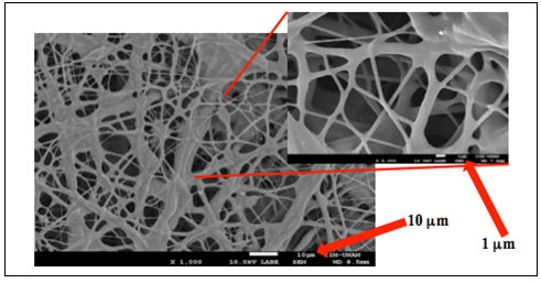 | Figure 10. PGS-PCL UV crosslinked fibers |
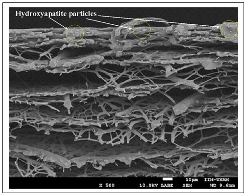 | Figure 11. Co-extruding PGS-PCL fibers in layer by layer, at different loads of PCL, whit 25% hydroxyapatite particles |
4. Conclusions
- Since the mesenchymal cells culture protocols require more extended study biomedical approach, we only claim the design and construction of the co-extruder, which allows the extrusion of films and electrospinning with the formation of crosslinked fibers, for the potential of soft and hard tissue regeneration. Therefore we suggest that we have achieved a novel design and simple and cheap fabrication of an extruder that provides a method for co-extruding engineering plastics, oppening the possibility of adding new plastics at different proportions to produce homogeneous mixtures of copolymers or related polymers with a wide variety of links on structural properties. In electrospinning mode, this design allows fabricating scaffolds that can vary according to the composition and distribution of the shape and size of the micro and nano fibers, allowing for the production of scaffolds with a wide range of compositions, porosities and mechanical properties.
ACKNOWLEDGEMENTS
- The authors express their gratitude to Dr. Augusto Jacobo Montiel Castro for language assistance in the drafting of this document.