-
Paper Information
- Next Paper
- Paper Submission
-
Journal Information
- About This Journal
- Editorial Board
- Current Issue
- Archive
- Author Guidelines
- Contact Us
American Journal of Biomedical Engineering
p-ISSN: 2163-1050 e-ISSN: 2163-1077
2016; 6(1): 12-18
doi:10.5923/j.ajbe.20160601.02

Impacts of Robotic Compliance and Bone Bending on Simulated in vivo Knee Kinematics
 Abstract
 Reference
 Full-Text PDF
 Full-text HTML
Rebecca J. Nesbitt1, Nathaniel A. Bates2, Teja D. Karkhanis1, Grant Schaffner3, Jason T. Shearn1
1Department of Biomedical Engineering, University of Cincinnati, Cincinnati, USA
2Department of Orthopedic Surgery, Mayo Clinic, Rochester, USA
3Department of Aerospace Engineering & Engineering Mechanics, University of Cincinnati, Cincinnati, USA
Correspondence to: Nathaniel A. Bates, Department of Orthopedic Surgery, Mayo Clinic, Rochester, USA.
| Email: |  |
Copyright © 2016 Scientific & Academic Publishing. All Rights Reserved.
This work is licensed under the Creative Commons Attribution International License (CC BY).
http://creativecommons.org/licenses/by/4.0/

Robotic testing offers researchers the opportunity to quantify native tissue loads for the structures of the knee joint during activities of daily living. These loads may then be translated into design requirements for future treatments and procedures to combat the early onset of knee degeneration following an injury. However, high knee loads during testing have the potential to deflect a robotic end effector and cause inaccuracies in the applied kinematics. Furthermore, bone bending could also induce kinematic change. This study aimed to quantify the effects of robotic compliance and bone bending on the accuracy of simulated in vivo kinematics in a KUKA KRC210 serial robotic system. Six (6) human cadaver knees were subjected to cyclic human gait motion while 6 DOF forces and torques were recorded at the joint. A Vicon T-Series camera system was used to independently record the applied kinematics. Periods of highest kinematic deviation occurred during instances of low joint loading, suggesting negligible levels of forced deflection for simulations of moderate levels of activity while results of this small study indicate that high physiologic loading poses low risk of deviation from target kinematics, further testing is necessary to confirm.
Keywords: Knee, Robotics, Simulation, Gait, Kinematics
Cite this paper: Rebecca J. Nesbitt, Nathaniel A. Bates, Teja D. Karkhanis, Grant Schaffner, Jason T. Shearn, Impacts of Robotic Compliance and Bone Bending on Simulated in vivo Knee Kinematics, American Journal of Biomedical Engineering, Vol. 6 No. 1, 2016, pp. 12-18. doi: 10.5923/j.ajbe.20160601.02.
Article Outline
1. Introduction
- Current treatment and reconstruction methods of native knee tissues fail to prevent the early onset of osteoarthritis (OA) and knee joint degeneration. [1] Due to the difficulties associated with the identification of unmet functional demands via direct in vivo measurement, many researchers have developed robotic testing platforms to study tissues during simulated kinematics in the laboratory. [2-8] These methodologies allow for the in vitro investigation of mechanical behaviors within the tibiofemoral joint during simulated clinical tests [6, 9-11] as well as in vivo recorded gait [12] and athletic tasks. [13] It has been demonstrated that these robotic models can reproduce joint motion with excellent intra- and inter-specimen reliability. [13] However, this reliability does not implicate that robotic models of joint articulation are without limitation.One such robotic limitation lies within the relative joint stiffness of the robotic manipulator and biologic specimen to be examined. [14] While several studies have demonstrated highly accurate methods of collecting kinematic data during activities of daily living (ADLs), [15-21] only limited data exists to support the accurate reproduction of these kinematics on human knee specimens using robotics. [13, 22] Further, though the referenced study comments on the reliability of robotic simulation with identical input, it does not explicitly quantify the influence of confounding factors such as system stiffness. While inputs would be precisely executed in theoretical systems with infinite stiffness, real systems show some degree of compliance, which makes it possible for the high knee loads generated during ADLs to alter the path of a robotic end effector or cause bone bending during testing. [14] This could result in altered kinematics applied to the joint. Accurate reproduction of in vivo kinematics requires that the system itself be much stiffer than the test object (the knee joint). While this is intuitive, the actual compliance of the robot and bony fixation interfaces in our lab have yet to be quantified. The objective of this study was to better understand the implications of system stiffness and to assess deviation within our own robotic laboratory model. Specifically, this study aimed to 1) apply previously recorded in vivo kinematics to human knees in vitro, 2) independently measure simulated kinematics and applied loads, 3) quantify the effects of robotic compliance and/or bone bending. This information will allow for the assessment of the kinematic accuracy of applied physiologic motions, and will be invaluable to proceed with this robotic testing platform in the investigation of more aggressive ADLs that produce higher loads across the joint. It was hypothesized that; a) the kinematic errors generated from the present robot model would be smaller in magnitude than previously reported kinematic errors associated with in vivo motion analysis, and that b) the magnitudes of these kinematic errors would correlate to magnitudes of joint loading for any given time point.
2. Materials and Methods
2.1. Robotic Manipulation
- Three specimens were procured and successfully tested from the University of Cincinnati Body Donor program and a tissue bank (Anatomy Gifts Registry, Hanover, MD) with a mean age of 77.7 ± 19.6 year and mass of 71.9 ± 21.1 Kg. All specimens were dissected free of soft tissue, leaving only the menisci and the cruciate and collateral ligaments with surrounding joint capsule intact. For each specimen, the tibia was potted into a custom-built adjustable fixture using PMMA bone cement. A PMMA mold was also applied to the femur as close to the tibiofemoral joint as possible, which allowed the bone to be rigidly bolted into a fixture on the stationary testing platform where the simulations were performed. Detailed accounts of specimen preparation and mounting are documented in previous literature. [7]A six-camera, infra-red motion tracking system externally recorded specimen motion (Vicon; T-Series). Sixteen (16) reflective markers (10mm diameter) were attached directly to the bony anatomy of each specimen with glue and double-sided tape. Clusters of 4 markers each were attached to 1) the base of the robotic end effector, 2) near the tibiofemoral joint line of the proximal tibia, 3) near the tibiofemoral joint line at the distal femur, and 4) the proximal femur (Figure 1). Markers were placed as close to the joint landmarks as possible to prevent relative motion between them, allowing the cameras to capture the true anatomic motion of the knee. The cameras were placed to surround the robot work volume and marker trajectories were sampled throughout simulation at 120 Hz. Camera calibrations revealed an average residual of 0.674 ± .09 mm.
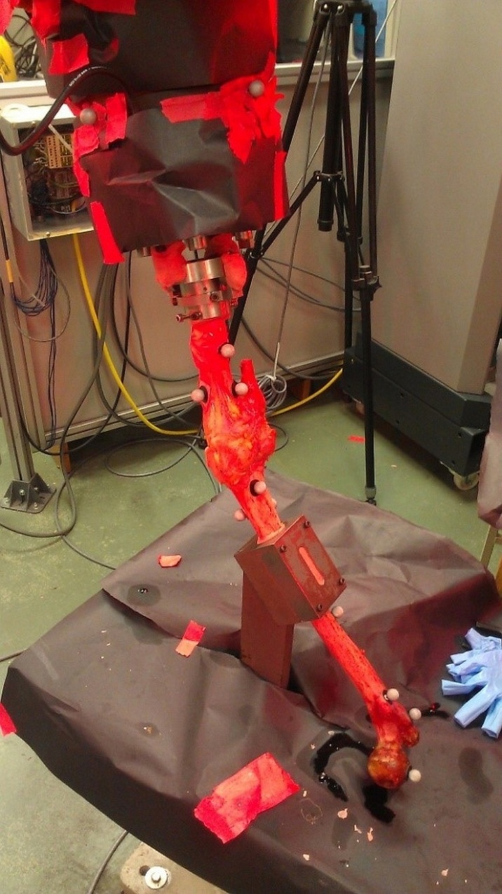 | Figure 1. Posterior view of a specimen with reflective markers attached. All other potentially reflective surfaces were covered with black matte paper |
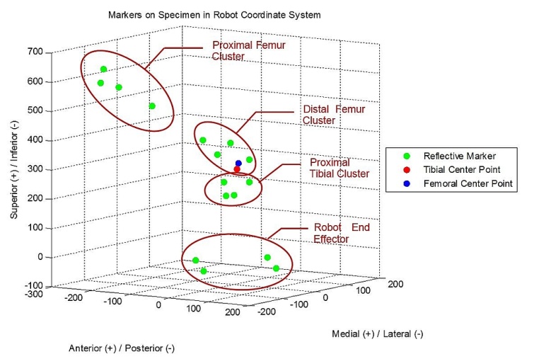 | Figure 2. Reflective marker positions as measured in the robotic coordinate system using the CMM. Tibial and femoral center points are examples of bony landmarks used to define the tibial and femoral coordinate systems. Absolute distances from bony landmarks to each of the markers in the closest cluster were used to place landmarks within the marker coordinate system. This depiction is vertically inverted compared to Figure 1 |
2.2. Data Analysis
- Forces and torques were filtered using a Fourier transfer to eliminate high frequency noise and were normalized to body weight before being averaged into a single cycle. Marker data was labeled within the Vicon iQ software workspace and exported to spreadsheets. A custom MATLAB script cleaned the data by unifying trajectories for markers of the same label and eliminating dual instances caused by artifact. A moving average filter applied to each DOF of data extracted noise above 20 Hz. All 10 test cycles were then averaged together to establish overall marker trajectories for a gait cycle. Test cycles missing full or partial spans of data due to “lost” markers were eliminated from the overall calculation. Standard deviations in cycle trajectory averaged approximately 0.3 mm.Marker data was then used to generate independently recorded anatomic kinematics at the knee joint itself. Because of the setup alignment of the tibia with the robotic end effector, the robotic coordinate system and the tibial aspect of the joint coordinate system (JCS) are identical in unloaded positions while the femoral aspect of the JCS remains stationary throughout testing (Figure 3). Anatomic kinematics reported by the robotic system assume that the tibial and femoral bones are rigid and that offsets from each bone’s JCS to the known or stationary fixture positions are constant throughout testing. However, even with short distances from the joint to each of the fixtures, the bones may be able to flex with respect to the fixtures in relatively high load conditions, which could cause deviation from the reported kinematics. Therefore, markers were clustered as close to the tibial and femoral JCS landmarks as possible to minimize relative motion between them, allowing the camera system to independently assess the position of the actual JCS during testing.
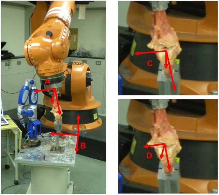 | Figure 3. Robotic test setup including each of the coordinate systems referenced in this study: A) Robotic coordinate system, B) Marker coordinate system, C) Femoral coordinate system, D) Tibial coordinate system |
2.3. Eliminated Data
- The three specimens were verified to be orthogonal by the CMM during setup at a zero-load condition. The average femoral orthogonality of the remaining three specimens was 0.998 ± 0.002, and average tibial orthogonality was 0.989 ± 0.015. Instances do occur where we are unable to derive orthogonal bony coordinate systems from a given specimen’s recorded marker data. The calculated coordinate systems from such specimens are never orthogonal enough to achieve numerical stability and prevent mathematically accurate calculations kinematics. Accordingly, any tested specimens that fell within this category were excluded from the present investigation.
3. Results
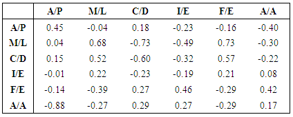
- Using only orthogonal data across the gait cycles of each of the 3 numerically stable specimens, the average anterior/posterior kinematic error of the tibia with respect to the femur was calculated at 8.1 ± 13.6 mm posterior; medial/lateral error at 6.9 ± 7.8 mm medial; superior/inferior error at 6.3 ± 9.6 mm superior; internal/external error at 3.0 ± 6.9° external; flexion/extension error at 5.1 ± 5.0° flexed; and ad/abduction error at 6.8 ± 3.9° abducted compared to the input kinematics (Figure 4). Highest deviations from the target kinematics occurred during the swing phase of gait, when knee loads were at their lowest (Figure 5). Correlation coefficients of the same subgroup were largest for medial deviation and medial force (0.68), medial deviation and distractive force (-0.73), and medial deviation and flexion torque (0.73, Table 1).However, considering only one specimen with the most orthogonal data, average anterior/posterior kinematic error was calculated at only 2.1 ± 0.6 mm anterior; medial/lateral error at 1.6 ± 1.1 mm medial; superior/inferior error at 0.8 ± 0.4 mm inferior; internal/external error at 0.1 ± 9.6° external; flexion/extension error at 1.0 ± 4.2° flexed; and ad/abduction error at 3.0 ± 1.0° abducted compared to the input kinematics. Correlation coefficients with the corresponding load data were much lower, with a maximum coefficient of only 0.47 for anterior deviation compared with compressive load.All correlation coefficients were less than the critical value of .811.
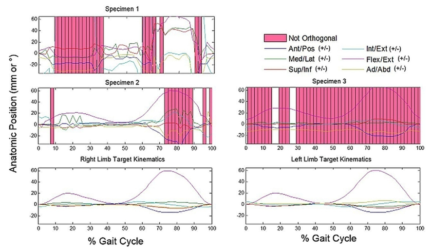 | Figure 4. Comparisons of calculated and target anatomic positions of the tibial coordinate system with respect to the femoral coordinate system in each of the 3 specimens resulting in orthogonal bony coordinate systems for at least one time point during gait. Deviations from target kinematics were greatest during periods of increased flexion |
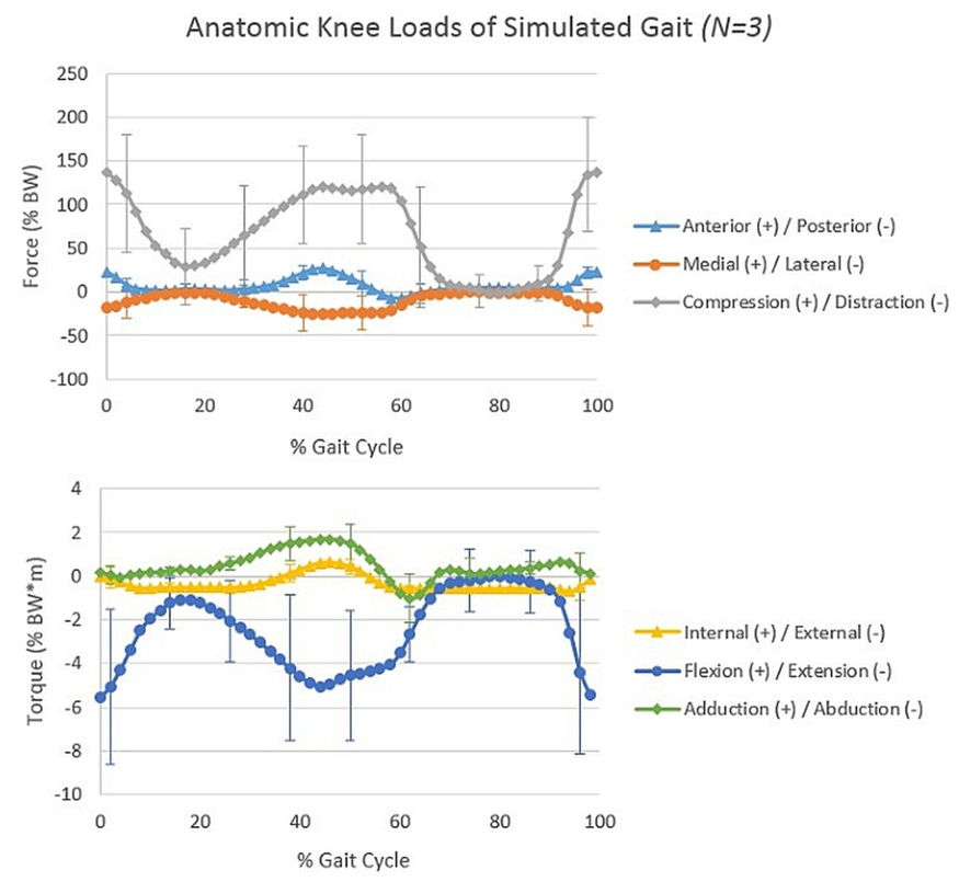 | Figure 5. Average dynamic knee forces and torques of the 3 orthogonal specimens, normalized to body weight, throughout a simulated gait cycle with standard deviation error bars. Heel strike corresponds to 0% and 100% gait. Toe-off occurs at 64% of gait. Heel strike and push-off demonstrate the highest loading values during gait |
4. Discussion
- The present investigation examined the effects of system stiffness relative to tibiofemoral joint kinematics during an in vitro gait simulation. It was hypothesized that a) the kinematic errors generated from the present robot model would be smaller in magnitude than previously reported kinematic errors associated with in vivo motion analysis , and that b) the magnitudes of these kinematic errors would correlate to magnitudes of joint loading for any given time point.The present data partially supported the hypotheses. Mean errors from skin-based markers throughout a gait cycle were 9.0 mm anterior/posterior, 6.2 mm medial/lateral, 4.4 mm superior/inferior, 2.5° internal/external, 2.6° flexion/ extension, and 3.3° ad/abduction. [16] These magnitudes generally increased when evaluated during a more dynamic task such as athletic cutting. [15, 16] Error values from the most orthogonal subject in the present study were smaller in magnitude than these previously reported bone pin versus skin marker errors throughout the gait cycle. However, the average magnitude of errors across all three subjects were greater than those previously reported from in vivo captures. During the present study, the most orthogonal specimen created a simulation that maintained greater accuracy than the current accepted standard for in vivo 3D motion analysis, while less-orthogonal systems did not.Although verified calibration and calculation techniques were used to complete and analyze this study, [7, 8, 12] only half of the specimens tested generated usable results as defined in the methodology. This was due to errors in orthogonality of mathematically reconstructed bony coordinate systems during gait simulation, leaving true anatomic position impossible to accurately calculate. These errors may have been generated in two ways: 1) The method of calculating and placing anatomical landmarks into the marker coordinate system was not accurate enough to maintain orthogonality. This includes possible marker occlusion due to camera placement and the introduction of error by prodding markers with the CMM tip, itself; 2) While CMM data confirmed orthogonality during limb setup at zero load, bone bending caused landmark positions to shift relative to one another during testing, leading to physical orthogonality disparities.With residuals of almost 1 mm in magnitude in the Vicon system, the inherent system error may have easily been high enough to promote inconsistencies and calculation error when solving for landmark positions. Unfortunately, these landmark position calculations could not be avoided in the current study, as the working envelope of the CMM prevented the marker and robotic coordinate systems from being dually measured by the same equipment. Accordingly, it is possible that these error sources would prevent our calculations from accurately placing marker positions within the system despite the bony constructs maintaining an anatomic orthogonality.On the other hand, bone deformation could be the culprit if to relative motion between markers. Small perturbations in the motion path of robotically simulated joint articulations can create significant loading differences. [25, 26] On a series robot, a 1.0 mm shift in the applied compression position altered the corresponding joint compression forces by 359.4 ± 8.5 N during the stance phase of gait. [26] Similarly, on a parallel robot system, perturbations of 0.5 mm altered ligament loading by between 34% and 110%. [25] However, orthogonality errors in the present investigation were not accompanied by these drastic alterations in force or torque at the joint. For this reason, a mathematical or marker/camera placement error is more probable than a physical mal-alignment due to significant bone bending.Even with computational challenges, a subset of data was successfully presented which compares actual kinematic output with target values during simulations of anatomic motion. Results showed that kinematic deviations were not significantly linked with the amount of load experienced at the knee joint (all correlation coefficients <.811). In fact, most deviation occurred during flexed periods of gait when loads were low – namely mid stance and swing. These errors may be explained by the flexion of the specimen interfering with the line of sight between one or more markers and the more posteriorly positioned cameras. This outcome suggests that end effector deflection truly is negligible compared to other accepted sources of error associated with in vivo motion analysis.
5. Conclusions
- The results indicate that kinematics of simulated activities producing high loads at the joint are not at an increased risk to be influenced by bone bending and/or robotic compliance. Periods of high-loading did not correspond to decreased orthogonality, nor did they correlate to increased kinematic deviation. However, future studies employing higher resolution equipment are necessary to confirm these findings.
ACKNOWLEDGEMENTS
- This work was supported by the National Institutes of Health (R01 AR056660 & R01 AR056259). The authors would like to acknowledge Guarav Mukherjee for his assistance in setting up and calibrating the Vicon system for use in our robotics laboratory.
References
| [1] | A. von Porat, E. M. Roos, and H. Roos, "High prevalence of osteoarthritis 14 years after an anterior cruciate ligament tear in male soccer players: a study of radiographic and patient relevant outcomes," Ann Rheum Dis, vol. 63, pp. 269-73, Mar 2004. |
| [2] | J. W. Xerogeanes, R. J. Fox, Y. Takeda, H. S. Kim, Y. Ishibashi, G. J. Carlin, et al., "A functional comparison of animal anterior cruciate ligament models to the human anterior cruciate ligament," Annals of Biomedical Engineering, vol. 26, pp. 345-352, 1998. |
| [3] | A. Kanamori, S. L. Woo, C. B. Ma, J. Zeminski, T. W. Rudy, G. Li, et al., "The forces in the anterior cruciate ligament and knee kinematics during a simulated pivot shift test: A human cadaveric study using robotic technology," Arthroscopy, vol. 16, pp. 633-9, Sep 2000. |
| [4] | Y. Fukuda, S. L. Woo, J. C. Loh, E. Tsuda, P. Tang, P. J. McMahon, et al., "A quantitative analysis of valgus torque on the ACL: a human cadaveric study," J Orthop Res, vol. 21, pp. 1107-12, Nov 2003. |
| [5] | S. P. Darcy, R. H. Kilger, S. L. Woo, and R. E. Debski, "Estimation of ACL forces by reproducing knee kinematics between sets of knees: A novel non-invasive methodology," J Biomech, vol. 39, pp. 2371-7, 2006. |
| [6] | S. L. Woo, S. D. Abramowitch, R. Kilger, and R. Liang, "Biomechanics of knee ligaments: injury, healing, and repair," Journal of Biomechanics, vol. 39, pp. 1-20, 2006. |
| [7] | D. V. Boguszewski, J. T. Shearn, C. T. Wagner, and D. L. Butler, "Investigating the effects of anterior tibial translation on anterior knee force in the porcine model: is the porcine knee ACL dependent?," Journal of Orthopaedic Research, vol. 29, pp. 641-6, May 2011. |
| [8] | R. J. Nesbitt, S. T. Herfat, D. V. Boguszewski, A. J. Engel, M. T. Galloway, and J. T. Shearn, "Primary and secondary restraints of human and ovine knees for simulated in vivo gait kinematics," Journal of Biomechanics, vol. 47, pp. 2022-2027, 2014. |
| [9] | S. L. Woo, R. E. Debski, A. J. Vangura, J. D. Withrow, T. M. Vogrin, E. K. Wong, et al., "Use of robotic technology to study the biomechanics of ligaments and their replacements," Operative Techniques in Orthopaedics, vol. 10, pp. 87-91, 2000. |
| [10] | S. L.-Y. Woo and R. E. Debski, "Robotics technology and ligament research: from in-vitro to in-vivo biomechanics," BED, vol. 42, pp. 137-138, 1999. |
| [11] | S. L.-Y. Woo, R. E. Debski, E. K. Wong, M. Yagi, and D. Tarinelli, "Use of Robotic Technology for Diarthrodial Joint Research," Journal of Science and Medicine in Sport, vol. 2, pp. 283-297, 1999. |
| [12] | S. T. Herfat, D. V. Boguszewski, and J. T. Shearn, "Applying simulated in vivo motions to measure human knee and ACL kinetics," Annals of Biomedical Engineering, vol. 40, pp. 1545-53, Jul 2012. |
| [13] | N. A. Bates, R. J. Nesbitt, J. T. Shearn, G. D. Myer, and H. T. E., "A Novel Methodology for the Simulation of Athletic Tasks on Cadaveric Knee Joints with Respect to In Vivo Kinematics," Annals of Biomedical Engineering, vol. 43, pp. 2456-2466, 2015. |
| [14] | J. M. Rosvold, S. P. Darcy, R. C. Peterson, Y. Achari, D. T. Corr, L. L. Marchuk, et al., "Technical issues in using robots to reproduce joint specific gait," Journal of Biomechanical Engineering, vol. 133, p. 054501, May 2011. |
| [15] | D. L. Miranda, M. J. Rainbow, J. J. Crisco, and B. C. Fleming, "Kinematic differences between optical motion capture and biplanar videoradiography during a jump-cut maneuver," Journal of Biomechanics, vol. 46, pp. 567-73, Feb 1 2013. |
| [16] | D. L. Benoit, D. K. Ramsey, M. Lamontagne, L. Xu, P. Wretenberg, and P. Renstrom, "Effect of skin movement artifact on knee kinematics during gait and cutting motions measured in vivo," Gait Posture, vol. 24, pp. 152-64, Oct 2006. |
| [17] | D. L. Benoit, D. K. Ramsey, M. Lamontagne, L. Xu, P. Wretenberg, and P. Renstrom, "In vivo knee kinematics during gait reveals new rotation profiles and smaller translations," Clin Orthop Relat Res, vol. 454, pp. 81-8, Jan 2007. |
| [18] | M. A. Lafortune, P. R. Cavanagh, H. J. Sommer III, and A. Kalenak, "Three-dimensional kinematics of the human knee during walking," Journal of Biomechanics, vol. 25, pp. 347-357, 1992. |
| [19] | C. Reinschmidt, A. J. Van den Bogert, A. Lundberg, B. M. Nigg, N. Murphy, A. Stacoff, et al., "Tibiofemoral adn tibiocalcaneal motion during walking: external vs. skeletal markers," Gait and Posture, vol. 6, pp. 98-109, 1997. |
| [20] | C. Reinschmidt, A. J. van den Bogert, N. Murphy, A. Lundberg, and B. M. Nigg, "Tibiocalcaneal motion during running, measured with external bone markers," Clinical Biomechanics, vol. 12, pp. 8-16, 1997. |
| [21] | C. Reinschmidt, A. J. van den Bogert, B. M. Nigg, A. Lundberg, and N. Murphy, "Effect of skin movement on the analysis of skeletal knee joint motion during running," Journal of Biomechanics, vol. 30, pp. 729-732, 1997. |
| [22] | N. A. Bates, R. J. Nesbitt, J. T. Shearn, G. D. Myer, and T. E. Hewett, "Relative Strain in Anterior Cruciate Ligament and Medial Collateral Ligament during Simulated Jump Landing and Sidestep Cutting Tasks: Implications for Injury Risk," Am J Sport Med, vol. 43, pp. 2259-2269, 2015. |
| [23] | E. S. Grood and W. J. Suntay, "A Joint Coordinate System for the Clinical Description of Three Dimensional Motions: Application to the Knee," Journal of Biomechanical Engineering, vol. 105, pp. 136-144, 1983. |
| [24] | A. Mundermann, C. O. Dyrby, D. D. D'Lima, C. W. Colwell, Jr., and T. P. Andriacchi, "In vivo knee loading characteristics during activities of daily living as measured by an instrumented total knee replacement," Journal of Orthopaedic Research, vol. 26, pp. 1167-72, Sep 2008. |
| [25] | R. A. Howard, J. M. Rosvold, S. P. Darcy, D. T. Corr, N. G. Shrive, J. E. Tapper, et al., "Reproduction of in vivo motion using a parallel robot," J Biomech Eng, vol. 129, pp. 743-9, Oct 2007. |
| [26] | S. T. Herfat, D. V. Boguszewski, R. J. Nesbitt, and J. T. Shearn, "Effect of perturbing a simulated motion on knee and anterior cruciate ligament kinetics," Journal of Biomechanical Engineering, vol. 134, p. 104504, Oct 2012. |
| [27] | E. A. Pedersen, M. P. Akhter, D. M. Cullen, D. B. Kimmel, and R. R. Recker, "Bone response to in vivo mechanical loading in C3H/HeJ mice," Calcif Tissue Int, vol. 65, pp. 41-46, July 1999. |