-
Paper Information
- Paper Submission
-
Journal Information
- About This Journal
- Editorial Board
- Current Issue
- Archive
- Author Guidelines
- Contact Us
American Journal of Biomedical Engineering
p-ISSN: 2163-1050 e-ISSN: 2163-1077
2015; 5(4): 116-129
doi:10.5923/j.ajbe.20150504.02

System Architecture and Implementation of a Wireless-Based Home Health Care Monitoring System Intended for Use in a Medical Center Environment
 Abstract
 Reference
 Full-Text PDF
 Full-text HTML
Barry K. Gilbert1, Mark E. Vickberg1, Daniel J. Schwab1, Clifton R. Haider1, Orhun H. Kantarci2, Ivana T. Croghan3, Robert A. Sainati1
1Special Purpose Processor Development Group, Department of Physiology and Biomedical Engineering, Mayo Clinic, Rochester, USA
2Department of Neurology, Mayo Clinic, Rochester, USA
3Department of Medicine, Mayo Clinic, Rochester, USA
Correspondence to: Barry K. Gilbert, Special Purpose Processor Development Group, Department of Physiology and Biomedical Engineering, Mayo Clinic, Rochester, USA.
| Email: |  |
Copyright © 2015 Scientific & Academic Publishing. All Rights Reserved.
This work is licensed under the Creative Commons Attribution International License (CC BY).
http://creativecommons.org/licenses/by/4.0/

We describe an end-to-end wireless and/or wireline approach to a continuous health care monitoring and alerting system for individual free-living patients in their homes, intended for use as a clinical tool set by medical professionals based in medical center or hospital environment. The system begins with the patient being monitored in his/her private home, who wears a small physiological monitoring, recording, and wireless transmission unit. This body-worn unit communicates wirelessly with a transceiver gateway positioned at a convenient location in the home. The gateway in turn reformats the received data into conventional Ethernet packets, which can then be transmitted across any channel capable of transporting such packets. The data packets traverse any of four separate wireless or wired channels to a medical center, where they are fed into a graphical user interface for viewing and appropriate clinical decision-making by medical professionals. All of the elements of this proposed system have been demonstrated with actual hardware and software over the past four years.
Keywords: Body-Worn unit, Real-Time operating system, Biometric sensors, ECG, Real-Time clock, Wireless transmission, Wireline transmission, Satellite transmission, Biomedical electronics
Cite this paper: Barry K. Gilbert, Mark E. Vickberg, Daniel J. Schwab, Clifton R. Haider, Orhun H. Kantarci, Ivana T. Croghan, Robert A. Sainati, System Architecture and Implementation of a Wireless-Based Home Health Care Monitoring System Intended for Use in a Medical Center Environment, American Journal of Biomedical Engineering, Vol. 5 No. 4, 2015, pp. 116-129. doi: 10.5923/j.ajbe.20150504.02.
Article Outline
1. Introduction: Clinical-Quality Home Health Care Monitoring and Its Potential Advantages
- Over the past decade, the operational model for the delivery of health care in the United States has been under evaluation across the spectrum of providers and insurers, with the primary intent of cost reduction while maintaining or improving the health of the population. Increasingly, patients are being clinically prioritized, or “triaged”, through a system that limits direct patient-physician interactions, employing allied health care professionals wherever possible at all stages of the process. Simultaneously, a smaller percentage of potential patients actually visit a medical center, whether because of costs to the patient, travel issues, or other variables. The value of employing continuous monitoring of the patient in his/her free-living environment is also under scrutiny, especially with the proliferation of what may be referred to as “consumer self-help devices’ such as activity monitors, step counters, and the like. Part of the debate should consider whether monitoring devices need to produce data of diagnostic quality, or whether “self-help” data is sufficient for use in generating reliable clinical decision-making. Several workers have developed body-worn units significantly better than the self-help devices [1-4], and a handful of studies have been conducted to compare and contrast these various classes of devices [5-14]. The data collected by these more clinically-oriented monitoring units is typically recorded or “logged” in on-board nonvolatile memory [1-14], which is useful when the units can be returned to the clinical teams for offloading and analysis [10-14]. The next logical step in this evolutionary process is the transmission of critical data, or snapshots of data, back to caregivers at a medical center or equivalent clinical facility. The ability to 1) track selected physiological and biochemical variables in near-real time, followed by 2) the transmission of both alerts and data back to a medical center system that can 3) analyze the incoming “raw” data, 4) convert it to actionable information, and then 5) act on the analyzed data, can have significant medical benefit. Serious medical issues, whether acute (e.g., cardiac arrhythmias post-cardiac surgery) or chronic (e.g., blood oxygen saturation variations in chronic obstructive pulmonary disease (COPD) or sleep apnea patients), could be detected early, thereby lowering the burden on the entire care delivery chain. Several teams have developed wearable wireless-equipped body-worn physiological monitors [15-16], but have not described a full implementation of such a system that can handle many different deployment situations through the selection of various components from a single overarching architecture.This manuscript discusses an easily modified, expanded, or repurposed architecture for a home health monitoring system, the elements of which have been in development in our laboratory over the past decade. We will describe an “end-to-end” monitoring system architecture based upon a set of concepts that are different from notional approaches that have appeared elsewhere. Our reasons for these architectural choices are explained as well.
2. System Architecture
2.1. The Body-Worn Unit
- The patient “end” of the home monitoring system that we are developing is a small, unobtrusive autonomous wireless-equipped, body-worn sensing, recording, and transmitting unit; autonomous in that it requires no interaction from the monitored individual, except to wear the unit. The wireless unit (Figure 1) is an evolving version of a body-worn non-wireless data logging system developed here over the past twelve years [8-9] that has been deployed in several clinical studies in our medical center [10-14]. Both the wireless and data-logger versions have common features: a “real time operating system”, or RTOS, running on an embedded microcontroller or microprocessor; a stable “real time clock” [9]; a nonvolatile memory store; an architecture that supports a number of potential sensors that may have analog or digital outputs, or both; the ability to accept a range of battery types and energy storage capacities; and an “electrically small” antenna designed to operate efficiently when placed close to the subject’s body.
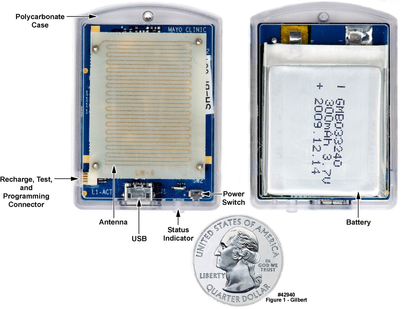 | Figure 1. Antenna-side and battery-side views of wireless-enabled body-worn unit with short-haul wireless transmission capability; unit supports three 3-axis accelerometers in addition to the wireless function. Note the meander line antenna. U.S. quarter (23 mm diameter) included for size comparison, and the 300 mAh label on the thin-film battery |
2.2. The Home Gateway
- The low-power wireless signal “packet” from the body-worn unit was detected by a “home gateway” (depicted in Figure 2) located in the subject’s home, which received the signal, reformatted it as needed, and retransmitted it, again in burst mode, back to a medical center, over any one of four possible long-haul transmission paths, as discussed below. The gateway was designed to transmit an acknowledgement signal back to the body-worn unit’s electronics. We have also designed and fabricated, but have not yet tested, a feature that will be important in a clinically fielded system: if the body-worn unit does not receive an acknowledgement signal from the gateway, it will increase its transmission power in programmable steps up to approximately 63 mW, and will continue to broadcast at this higher power until its battery is exhausted or until it eventually receives an acknowledgement from the gateway. In these initial feasibility demonstrations, encryption was not implemented; however, in a deployed system, encryption can be conducted at the body-worn unit using low-footprint encryption code [18] or at the gateway. Government regulation will dictate where the encryption is conducted. However, encryption at the gateway has the benefit of wall plug power availability, and the transmission distance from the body- worn unit to the home gateway will typically be less than thirty meters, thereby minimizing interception risk. The home gateway converts the as-transmitted packets into Internet Protocol packets, making them universally transportable. The first version of the home gateway was designed, fabricated, tested, and used in initial demonstrations of the real-time transport of data from informed-consent volunteers.
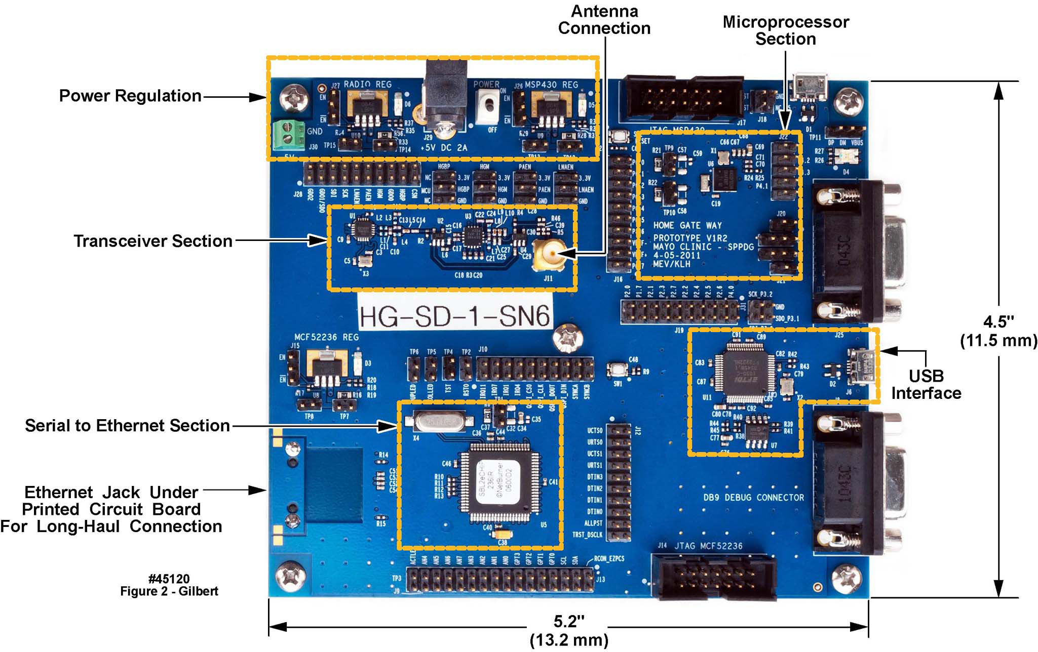 | Figure 2. Component-side view of the Mayo-designed prototype home gateway, with the functional sections labeled for clarity |
2.3. Testing the Combination of Body-Worn Unit and Home Gateway
- We tested the combination of body-worn unit and gateway system in the two-floor home of a volunteer. Figure 3 is a diagram of the volunteer’s home, illustrating various structures and items of furniture. The gateway was placed on a chair as indicated, and the volunteer, wearing the wireless-equipped body-worn unit transmitting a 1 mW signal, moved to different locations within the dwelling, implementing four different test conditions: with the unit at chest height with and without closed doors separating the unit from the gateway (two test conditions); and with the unit on the floor and covered by the volunteer’s body (two test conditions). A successful transmission was received at each location and body orientation for the transmission power level used for the test. The colored circles indicate the physical locations of the tests, with the associated numbers with reference to the test key in the lower leftmost portion of the figure. Note that even at only 1 mW of radio frequency (RF) power in the 900 MHz band, the signal was received at all locations.
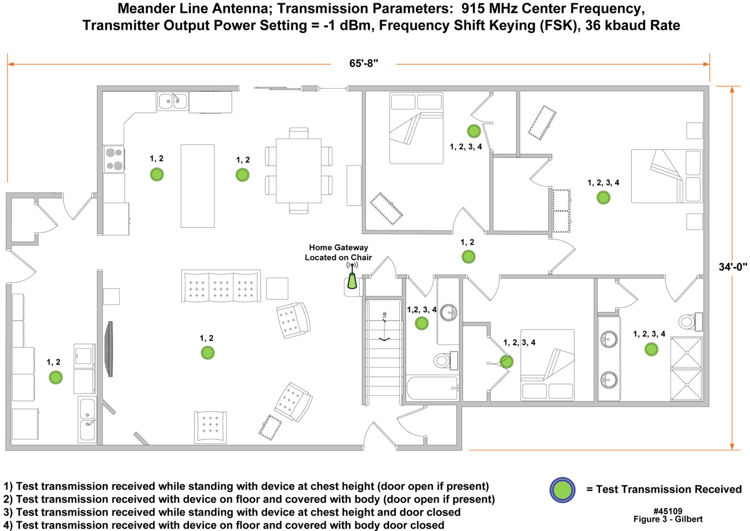 | Figure 3. Test of the wireless-equipped body-worn unit and the home gateway in the home of a volunteer, illustrating that RF link closure was established in locations using a centrally located gateway and approximately 1 mW of transmitter output power from the body-worn unit |
2.4. The Long-Haul Transmission Link
- We identified four full duplex communications options for transmitting the data packets back to a medical center, as illustrated in Figure 4: 1) cable modem or 2) asymmetric digital subscriber line (ADSL), hereafter referred to as “wireline” implementations; 3) “terrestrial wireless”; and 4) satellite communications. We demonstrated the cable modem implementation, but we did not test ADSL because ADSL typically works well only if the subscriber’s dwelling is within 4 km of a telephone company’s central office, and also because ADSL is gradually falling into disuse as cable penetration has become more prominent (50 million subscribers as of December 2013). For the terrestrial wireless implementation, we tested two different protocols, WIMAX and LTE (see below).
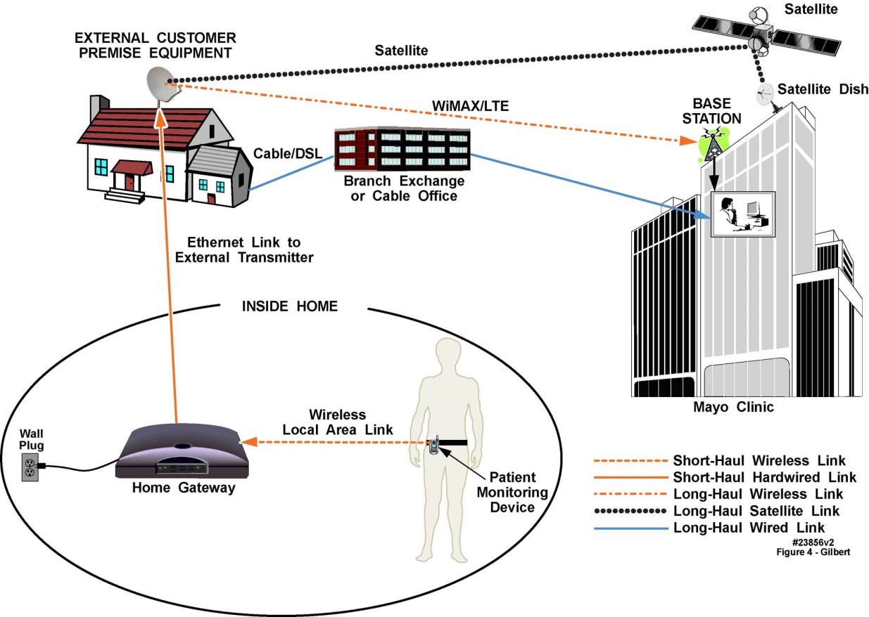 | Figure 4. Diagrammatic illustration of multiple approaches to establishing full duplex communication between a wireless-implemented body-worn physiological monitoring unit and a medical center. The cartoons in the oval illustrate those portions of the system that reside within the interior of the home. The cartoon of the home illustrates a notional antenna (shown larger than necessary, for illustration purposes) on the roof, though the antenna could be in an attic or on a high shelf. The branch exchange illustrates the link from the home if cable or DSL modems are used; and the large building on the right side of the diagram represents a medical center building. The home gateway is specially designed, not a Wi-Fi access point |
2.4.1. Terrestrial Wireless Transmission Demonstrations Using Engineering Test Data
- We began the investigation of this approach by acquiring a nationwide 10-year license from the FCC to 50 MHz of bandwidth at 3.65 GHz, a service referred to as the 3650-3700 MHz radio service band [19]. The architecture that we developed intentionally does not employ the use of the commercial cellular phone network, as will be discussed below. We demonstrated the complete end-to-end architecture three times, using surrogate components for some of the functional elements depicted in Figure 4: in Rochester MN (moderate urban environment), in La Crosse WI (light urban environment), and in Phoenix AZ (dense urban environment). In these initial studies, we transmitted engineering test data packets as a surrogate for actual physiological data. At 3650 MHz, the transmission range was 6 km typical, 10 km maximum. The data streams collected at these three locations were injected into each medical center’s connection to Mayo Clinic’s nationwide intranet, whence it was transported back to our laboratory in Rochester, MN. These tests confirmed that once the data was received at any medical facility, it could be transported by intranet and/or Internet to the point of analysis. Figure 4 illustrates the intended location of the long-haul RF antenna in the home of an individual being monitored, i.e., in the attic or on a high shelf facing toward the antenna on the nearby medical center or to a tower-mounted antenna. To avoid disturbing the homes of the volunteers, we deployed a heavy-duty extendable mast and antenna next to each dwelling, raised to a height that matched the height-above-ground of the attic of each of three dwellings, as depicted in Figure 5 (Scottsdale, AZ). The antenna for the medical center end of the RF link appears in Figure 6 (Franciscan Skemp Medical Center, La Crosse, WI).
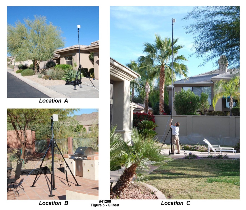 | Figure 5. Antenna and mast configuration for the RF transmission of engineering test data from the homes of several volunteers in Scottsdale AZ; receiving base station was located on a building at Mayo Clinic Scottsdale (not pictured) |
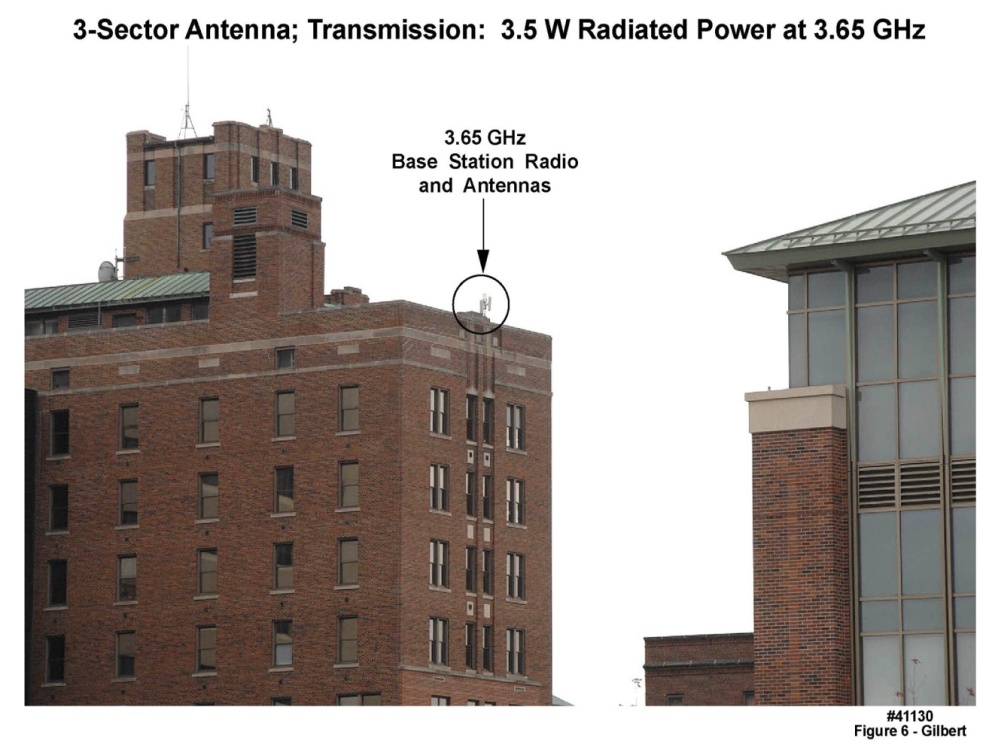 | Figure 6. Franciscan Skemp medical center building in La Crosse, WI, illustrating the positioning of the three-sector 3650 MHz full duplex antenna |
2.4.2. Satellite Transmission
- The region surrounding Rochester MN is characterized by a mixture of moderately dense urban and suburban environs, but in addition very large geographic areas which are characterized as deeply rural. Many such regions contain no or very few tall towers, and no tall buildings. Similarly, in rural mountainous terrain, the “reach” of terrestrial wireless may be constrained by the land conformation. To address these two issues, we attempted to demonstrate the use of a bidirectional satellite communications link (also diagrammed in Figure 4) using an Inmarsat satellite in geostationary orbit and a very small aperture terminal (VSAT) slightly larger than and with similar appearance to a typical laptop computer (the “screen” is actually the array antenna). This demonstration was unsuccessful, because the round-trip path delay exceeded the timeout loops in our electronics. A redesign would have alleviated this problem and should not be removed from consideration, because as indicated above, for some rural residences, very few other viable choices are evident.
2.5. Example of Raw Diagnostic-Quality Data Transported Across This Network Architecture
- We modified the wireless unit depicted in Figure 1 by attaching a small auxiliary circuit board to its motherboard; the auxiliary board contained ECG monitoring circuitry (Figure 7). The combined proof-of-concept circuit board provided the necessary combination of electronic components to deliver all the needed functions for a real-world test microcontroller and real-time firmware, battery, real-time clock, ECG circuitry, and transmission circuitry. In a fieldable version, the two circuit boards would be combined to create a compact unit similar in appearance to that of Figure 1.
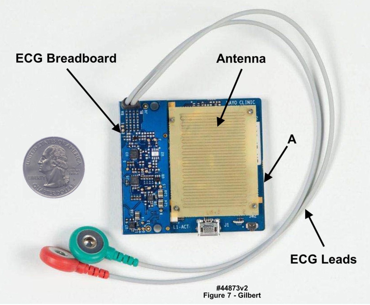 | Figure 7. Proof-of-concept wireless-enabled body-worn physiological monitoring unit employed to demonstrate real-time transmission of clinically valuable data from a wearer back to a medical center. Blue portion of board on left edge, marked “ECG Breadboard”, is ECG circuitry; right portion depicts meander-line antenna with wireless circuitry and microcontroller, marked “A”, beneath antenna. U.S. quarter (23 mm diameter) included for size comparison |
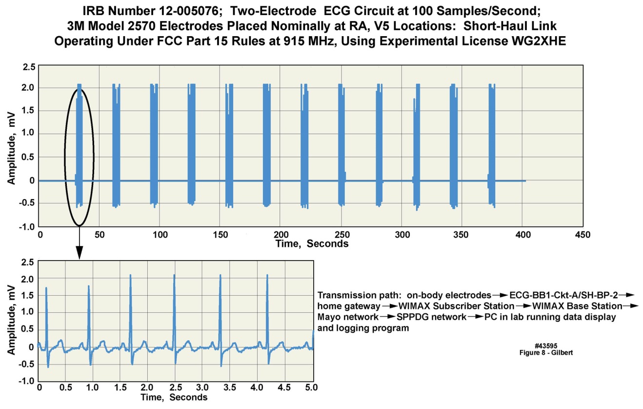 | Figure 8. Real-time digitized ECG waveform transmitted from a physiological monitoring unit placed on a volunteer, with the body-worn unit programmed to transmit five seconds of data out of every thirty elapsed seconds. Upper panel: a 375 second data snapshot. Lower Panel: a time-expanded view of one of the five-second “snapshots”. WIMAX long-haul transmission protocol was employed |
2.6. Arrival of Data Packets at the Medical Center and Subsequent Processing
- In our demonstration, when the data packets arrived at the medical center, they were transported through the medical center’s intranet to a server where, in a full clinical implementation, the header would be stripped from the packet and stored for later use, as would the payload itself. The raw data in the payload would be re-analyzed using more sophisticated algorithms or by allied health professionals, as described earlier. We demonstrated this capability by means of a specially written real-time graphical user interface (GUI) software package that displayed the data as it arrived from the transmission link from the home of the volunteer in Rochester, MN. Our intention is to make this GUI software more robust for use by clinical professionals with little time or inclination to concern themselves with “engineering details”.Three outcomes of the automated reanalysis are envisioned: 1) a false alarm; no action needed (false positives may be tolerated but must remain low to prevent observer fatigue; but we will attempt to minimize false negatives); 2) a critical medical event has been detected, in which case control is passed to a GUI in use by allied health professionals, for whatever health care action is appropriate; or 3) indeterminate, in which case, because the end-to-end transmission path is fully bidirectional (i.e., full duplex), the body-worn unit can be requested to send another raw data snapshot. Step 3 could be repeated a small number of times within a few tens of seconds, and if the results remain indeterminate, control would be passed to allied health professionals for immediate action.
2.6.1. Algorithms
- The algorithms will be subsumed into two categories: 1) simple, low-power-drain preliminary algorithms that will be programmed into the body-worn unit’s real-time operating system, to generate early and timely alerts; and 2) more sophisticated post processing algorithms, that will run on servers located at the medical center. Our medical center continues to develop sophisticated post processing algorithms, including a very comprehensive ECG analysis package that has been in use for several decades. Thus for the preliminary algorithms (e.g., real-time fall detection and reporting, and the detection of cardiac arrhythmias) we work with our clinical colleagues to develop or select the algorithms, and we will program them into the real-time environment. For the majority of clinical subspecialties the post processing algorithms will be identified and placed into production by our collaborators. We have demonstrated in MATLAB a cardiac rhythm algorithm which exactly reported changes in rhythm over a range of heart rates; however, this algorithm has not yet been programmed for real time operation. We have also demonstrated a prototype software framework and GUI that illustrates how the header data in the arriving packet would be used to warn an allied health professional team to an incoming alert based on the coded information in the packet header.
2.7. Selection of a “Best” Long-Haul Implementation for a Given Medical Center and Home Environment
- As we began to assess the range of options for cost-effective implementations of long-haul wireless connectivity for home health monitoring applications, we discovered that the universe of possibilities was much greater than we had originally believed. The task was so daunting that we rapidly realized that an algorithmic approach would be needed to resolve the fielding options on a case-by-case basis.
2.7.1. Deployment Options
- The number of deployment options as partially described above is very large. No single approach will be optimum from the perspective of efficacy, cost to the medical center, or cost to the monitored patient. For example, terrestrial wireless implementations must select among a number of transmission protocols, demographics, local terrain contours around a given medical center facility, land use, selected transmission frequency, and many other independent variables. Installation and subscriber costs for ADSL or cable modem vary by geographic region, provider, and service level. Many different offerings of satellite communications services, from “by-the-burst” to leasing of an individual transponder, are available. A formal detailed, continually-updated economic model, mapping a very large number of input variables, through a set of model equations, to result in a set of actionable dependent variables, must be developed to handle such a high degree of complexity. We collaborated with our Institution’s Division of Financial Planning and Analysis to create a multi-part model with these capabilities. The model contains sub-models for 700 MHz and 900 MHz implementations, and should be expanded to include a wireline sub-model, and a satellite communications sub-model. Finally, a number of payment and reimbursement models are available, which also must be examined as the implementation models evolve.
2.7.2. Carrier Frequency Selection for the Terrestrial Wireless Implementation Employing Signal Propagation Simulations
- RF propagation simulations conducted at both 3650 MHz (where we performedour physical field tests) and at 700 MHz, including terrain and land use elements, indicated that at a lower transmission frequency, e.g., in the 700 MHz range, the transmission radius, depending on local terrain conditions, would increase to 10 miles or more, and the amount of terrain covered per antenna (assuming omnidirectional antennas in the azimuthal plane) could be in the range of several hundred square miles, as illustrated in Figures 9 and 10. Figure 9 presents a pair of RF propagation simulations conducted with the software package EDX SignalPro, including both terrain and land use features, in the region around Rochester MN. Rochester is located in a natural bowl surrounded by hills at least two hundred feet higher than the bottom of the bowl, thereby limiting the RF transmission range at any given frequency. Radiated power levels as simulated in both the left panel (3650 MHz) and right panel (700 MHz) were limited to 3.5 watts, with the “medical center antenna” located on the top of a 22-story building at the center of the circle. The clear areas around the center of the circle are those exhibiting good-to-excellent RF coverage, which were roughly confirmed by actual physical RF signal strength measurements at a grid of locations around the circle’s center.
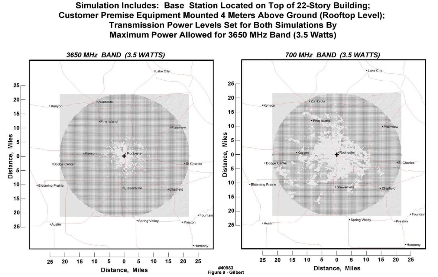 | Figure 9. Simulated RF signal propagation coverage for long-haul full duplex transmission path, incorporating actual terrain and land use variables in a region centered around downtown Rochester, MN, at 3650 MHz and at a hypothetical center frequency of 700 MHz. Clear regions in each chart illustrate land areas with good RF coverage; stippled regions indicate areas of insufficient RF signal strength to establish reliable communication between the building antenna and a residence. Land coverage from a single antenna is significantly greater at the lower frequency |
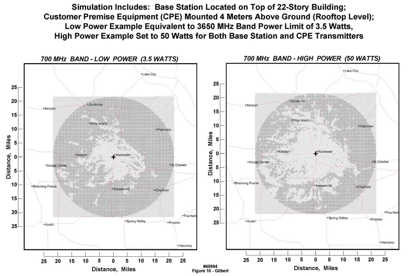 | Figure 10. Simulated RF signal propagation coverage for actual terrain and land use variables in a region centered around downtown Rochester, MN, at a carrier frequency of 700 MHz . Land coverage from a single antenna is significantly greater at 50 W radiated power (well above FCC-permitted levels, but perhaps allowable through variances in emergency situations) |
3. Architectural Elements of Commercial Wireless Systems Rendering Them Unattractive for This Application
- It has been widely discussed that home health monitoring can be conducted using the commercial cellular network in conjunction with specially prepared “apps” embedded into consumer “smart phones”. Although there is a role for such implementations, the pressure to employ “proven and available” technology is occurring without an understanding of the limitations of the commercial-consumer cellular network, and the motivations of the commercial carriers. Increasingly, the commercial cellular infrastructure is designed to address the average customer’s reliance on “smart phones” not only used for bidirectional voice calls, but very intensively for the downloading of massive amounts of digital data for such applications as “web surfing”. The commercial carriers have increasingly responded to these demands with network implementations which serve those specific customer applications, but also “cut corners” in important ways to maximize return on investment in plant and equipment. For example, because wireless providers are aware that at any given instant, many fewer than 100% of their subscribers are using the network, the wireless infrastructure is built out or “provisioned” to serve only a small percentage of the total number of subscribers; any additional equipment would, on average, go unused, i.e., generating “sunk costs” without return on the investment. Thus, whenever network usage increases beyond the “provisioning limit”, the system experiences a variety of operational anomalies: “dropped calls”, “garbling”, no-connects, etc. The wireless providers have learned that, unlike for the wired phone network engineered in the twentieth century under a “100% up-time, 100% usage” paradigm, the subscriber base will tolerate a significant amount of such anomalous behavior in exchange for convenience of usage. However, when confronted with a geographically broad event, e.g., September 11, 2001 in New York City and Washington DC and hurricane Katrina (August 25-31, 2005 in New Orleans) or the bombing of the Boston Marathon on April 15, 2013 [20-22], or a local disruptive event (e.g., a major fire in a large food processing plant centrally located in a small Midwestern town [23-24]), the commercial cellular systems tend to “crash”----because they are instantly overloaded. Further, with regard to light suburban-to-rural environments, cellular coverage can be “spotty”, in the sense that two residences separated by only a few hundred feet may experience differing levels of commercial cellular coverage---one may have good “reception” and the other none at all, disparities that are yet another but important form of unreliability.Second, as commented above, the nature of present cellular traffic patterns has caused the commercial cellular network to be optimized at its hardware and software levels for “volume downloads” of noncritical data (e.g., web data) which can be lost or garbled with generally low negative consequences. This customer base usage has driven the providers to create asymmetric full duplex networks, in which the provisioned download bandwidths exceed the supported upload bandwidths. Thus the “quality of service” (QOS) metric which is so important in the design of, e.g., high bandwidth fiber networks at the physical layer and data link layer, is not of first-order importance in the commercial cellular network; it is not designed for small-quantity high transport-rate uploads of time-critical and life-critical data. Stated alternately, the commercial cellular network, by design, is not intended for the types of critical information associated with individual patient monitoring and care in home or office environments. Traffic volume for patient monitoring will be low, geographically dispersed, and asymmetric in the opposite direction when compared to commercial cellular traffic. These requirements in turn argue for a low geographic density of antennas operating at the lowest possible wireless frequencies, for the home health monitoring paradigm, which can significantly mitigate deployment costs. Medical centers could install antenna towers on their buildings (as in our demonstrations); alternately or in addition, it is possible to contract with any of several commercial companies that supply antenna rental services and backhaul capability on towers positioned across the U.S.Third, an asymmetry exists between the capability for international volume manufacture of cell phones and tablet displays, versus the time that it takes to design, fabricate and deploy the corporate infrastructure to support the network traffic generated by these phones. As an example, several years ago, as large scale providers began to sell millions of “smart phones” each month, they were confronted with successive waves of traffic volume expansion, to the point at which traffic from the heaviest individual subscribers (largely high-volume downloads) were intentionally throttled by the carriers. As of this writing, there is now a discussion of the next wave of even higher bandwidth wireless network traffic based upon the new 5G protocol, promising average speeds of tens of Mb/second to individual users, with peak speeds even higher. This new 5G capability in turn will compel the providers to expend large amounts of capital, once again, to upgrade their networks, with the inevitable disruptions that accompany the broad fielding of new technologies. Summarizing, in our view the commercial cellular network is not the environment to be entrusted with life-critical data from our most vulnerable and dependent citizens.It is for the above reasons that we tested a transport architecture that can be considered as a “private network” approach, which is designed and provisioned specifically for the operating conditions to be generated by home health monitoring, including fast upload speeds, low density but life-critical traffic, and high QOS.
3.1. Involvement by the Federal Communications Commission (FCC) in the Eventual Widespread Implementation of Clinically-Oriented Home Health Monitoring
- Regardless of the transport mechanism selected for either the short-haul link (from the body-worn unit to the gateway) or the long-haul link (from the gateway to the medical center), the link’s operating parameters, such as frequency, allowed transmit power, and available bandwidth, as well as priority for frequency access in the case of primary or secondary users, or traffic control in terms of net-neutrality, are all regulated by the Federal Communications Commission (FCC). Additionally, further restrictions may be imposed by the owner/operator of the selected long-haul network (e.g., if a commercial satellite service is employed).For on-body communications, as well as very close (1-2 meters) off-body short-haul links, the newly designated FCC medical body area network (MBAN) protocol, along with the new IEEE 802.25.6 wireless standard, provide a new option that does not compete with the crowded WiFi and Bluetooth frequencies. Another option that uses very similar technology to the commercial cellular service (i.e., the LTE protocol, discussed earlier), but that operates under a very different “business model”, is the U.S. public safety broadband network (PSBN), which is gradually being implemented. Although use of the PSBN for individual health and safety has not been specifically codified in the most recent set of regulations, a positive response by the FCC to comments made by Mayo Clinic in the rulemaking process [25] regarding this type of use was received. Specifically, the FCC stated that “the Commission envisions that in providing health care services to the sick or injured … would be eligible users of the 700 MHz public safety spectrum.” Exercising this option would likely require further clarification, perhaps through a declaratory rulemaking or through modification of the existing rules through a petition by a consortium of potential users.
4. Summary
- We have described a prototype end-to-end full-duplex home health care monitoring system for individual patients, employing; 1) a wireless-capable body-worn unit supporting one or more sensors and including data packet generation and transmission; 2) a “home gateway” that receives the transmitted signal from the body-worn unit, and retransmits the packet to a medical center using any of four different transmission protocols; 3) a mechanism at the medical center for processing the packet contents to verify that a medical event may be under way; and 4) a display system intended for health care providers to allow the incoming data to be triaged rapidly. While the complete system remains experimental, every functional element has been demonstrated, including the real-time transport of clinically significant patient data.
ACKNOWLEDGEMENTS
- The authors wish to thank Dr. K. Bobis, C. Burfield, Dr. J. Fleischmann, T. Funk, C. Felton, P. Lenko, Dr. D. Mohr, S. Neumann, S. Polzer, S. Schuster, P. McCarty, D. Moertel, J. Prairie, D. Rowlands, G. Ryland, J. Schubert, and Dr. B. Smith, for their contributions to this work.