-
Paper Information
- Paper Submission
-
Journal Information
- About This Journal
- Editorial Board
- Current Issue
- Archive
- Author Guidelines
- Contact Us
American Journal of Biomedical Engineering
p-ISSN: 2163-1050 e-ISSN: 2163-1077
2015; 5(3): 79-85
doi:10.5923/j.ajbe.20150503.01
Intervertebral Implant Performance Based on Dynamic Stiffness Response
 Abstract
 Reference
 Full-Text PDF
 Full-text HTML
Antonio Valdevit, Marina Dawoud
Department of Chemistry, Chemical Biology and Biomedical Engineering, Stevens Institute of Technology, Hoboken, NJ, USA
Correspondence to: Antonio Valdevit, Department of Chemistry, Chemical Biology and Biomedical Engineering, Stevens Institute of Technology, Hoboken, NJ, USA.
| Email: |  |
Copyright © 2015 Scientific & Academic Publishing. All Rights Reserved.
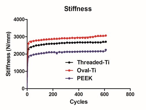
Intervertebral implant stiffness has traditionally been assessed under static conditions. The implant/vertebra construct was subjected to mechanical loading under dynamic conditions with resulting data analyzed using non-linear regression to extract dynamic response parameters. The intervertebral implants evaluated were a Threaded-Titanium, Oval-Titanium and Polyetheretherketone (PEEK) device. Specimens were loaded from -50N to -350N at 1Hz for 600 cycles with continuous load versus deformation acquired at cycle 10 and at 25 cycle intervals thereafter. Elastic stiffness for each design was averaged across respective cycle intervals and subjected to a nonlinear analysis. Resulting model parameters were compared using a 1 way ANOVA with a Tukey post-hoc test for statistical differences between designs. From the stiffness versus cycle non-linear regression analysis, a two phase exponential fit was the preferred model yielding two stiffness rate parameters (K1 and K2). No statistically significant differences were detected for the Fast component (K2), however, for the Slow component (K1), a statistically decreased stiffness rate was detected (P<0.01) for the Oval-Titanium implant compared to both the Threaded-Titanium and PEEK implants. Gradual stiffening of the Oval-Titanium implant may be mechanically advantageous during initial osteogenesis by providing a more stable mechanical environment, potentially reducing the risk for subsidence.
Keywords: Subsidence, Cyclic, Intervertebral, Stiffness
Cite this paper: Antonio Valdevit, Marina Dawoud, Intervertebral Implant Performance Based on Dynamic Stiffness Response, American Journal of Biomedical Engineering, Vol. 5 No. 3, 2015, pp. 79-85. doi: 10.5923/j.ajbe.20150503.01.
Article Outline
1. Introduction
- Vertebral endplate mechanics have been the focus of many investigations in an attempt to gain insight into the clinical outcome related to intervertebral implant devices. While many studies focus on the ultimate strength of the implant/vertebra construct with respect to subsidence and the mechanical properties associated with the implant, such studies do not address the sinusoidal or dynamic nature of physiological loading within the spine. [1, 2] To date, there are few investigations that conduct cyclic loading upon spinal elements. In these static studies, the overall stiffness is recorded through the load versus deformation data consists of a ratio attributed to the individual stiffness values associated with the implant and the vertebral body. The analogy may be made to a solid steel block upon soft compliant foam. If one were to load the materials, the resulting stiffness would be comparable to that of the foam in isolation. [3] Such a configuration was postulated by Kelly and co-workers in investigating the stress-strain relationships in trabecular bone where localized stress concentrations and material yielding in trabecular microstructure. It was reported that for a continuum representation of trabecular bone, a crushable foam plastic was required to illustrate the pressure dependent yield behaviour of trabecular bone. [4] Since the vertebral endplate is on average less than 1 mm thick condensed trabecular bone (Roberts 1989), several studies have concluded that the endplate stresses are dependent upon the modulus of elasticity associated with the underlying cancellous bone. [5, 6] Employing implant materials of varying modulus (cortical bone, titanium, and stainless steel) in a finite element model, Palm et al. determined that interface stresses were independent of implant material upon the intervertebral endplate. [7] The comprehension of implant/endplate load transfer and how the underlying trabecular bone responds due to cyclic loading and oscillatory fluid flows may be important in establishing clinical parameters for predisposition to implant subsidence. [8] Clinically, stiffening of the functional spinal unit (FSU) is a consequence of surgical intervention for fusion. While such a condition is unavoidable, one would ideally focus on a resulting mechanical configuration that will provide sufficient stability yet not result in stress shielding due to an overly stiff construct. The modulus of elasticity for trabecular bone has been reported to be approximately 0.10GPa [9], while titanium displays a modulus of 110GPa [10], reinforced PEEK a modulus of approximately 18GPa [10], and unfilled PEEK a modulus of 4GPa [10]. As most implant materials for interbody fusion display an increased modulus relative to trabecular bone, in order to provide sufficient stability through stiffening of the vertebra/implant construct without increasing stress upon the weak trabecular bone, the implant design should increase the contact area between the implant and the vertebral body and engage the outer rim for increased load bearing so as to decrease the loading in the weaker central region. [1, 2, 11] Under cyclic loading at 5Hz, Seidel et al. found that increases of vertebral area approximately 13% can increase the number of cycles to vertebral failure by almost a factor of two, while a decrease in vertebral area by the same amount can reduce the number of cycles to vertebral failure by approximately 2.5 times. [12]In this study, the construct implant/vertebra stiffness was computed under dynamic conditions and it was hypothesized that stiffening of the construct would occur. In addition, it was further hypothesized that the stiffening of the implant/vertebra construct could be assessed through non-linear regression leading to a parametric assessment of the implant performance.
2. Main Body
2.1. Methods
- Porcine L4 and L5 vertebral bodies (Animal Technologies, Tyler, TX) were employed so as to minimize the effects of bone density variability. The devices investigated in this study were a Threaded-Titanium cage in a paired configuration, (BAK, Spine-Tech, Minneapolis, MN) (Figure 1A), an oval shaped open titanium cage with a proprietary roughened surface, also referred to as the Oval-Titanium implant, (Endoskeleton TA, Titan Spine, Mequon, WI) (Figure 1B) and a closed PEEK cage with a spiked pattern, (AVS, Stryker, Kalamazoo MI) (Figure 1C).
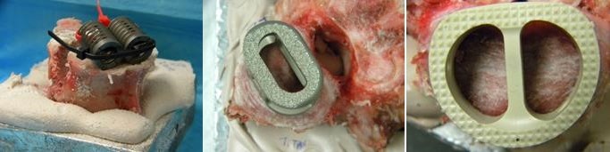 | Figure 1. Intervertebral implants tested. A) Threaded-Titanium (paired), B) Oval-Titanium, C) PEEK |
|
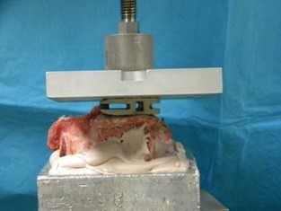 | Figure 2. Mechanical loading of implants employing a spherical connector to permit uniform contact between the loading platen and the implant |
 | (1) |
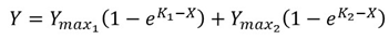
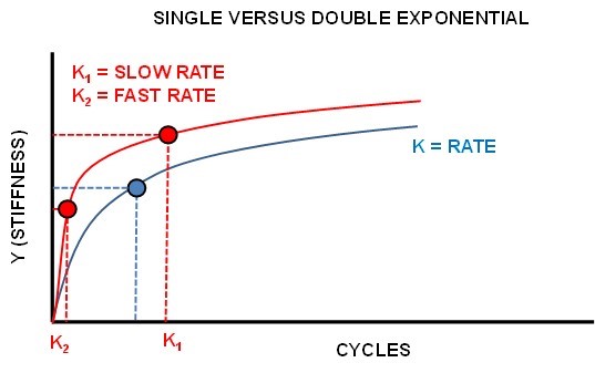 | Figure 3. Single versus Dual Exponential regression |
 | (2) |
2.2. Results
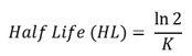
- The resulting average stiffness versus cycle number for each implant is seen in Figure 4. Each curve was fitted with a dual exponential fit versus a single exponential as determined by the AIC procedure with the R2 >0.92 for the fitted data.
 | Figure 4. Results of dual exponential fitting for Stiffness versus Cycle Number |
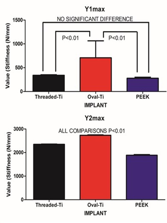 | Figure 5. Fitted amplitudes for the starting stiffness for the SLOW (A) and FAST (B) exponential components |
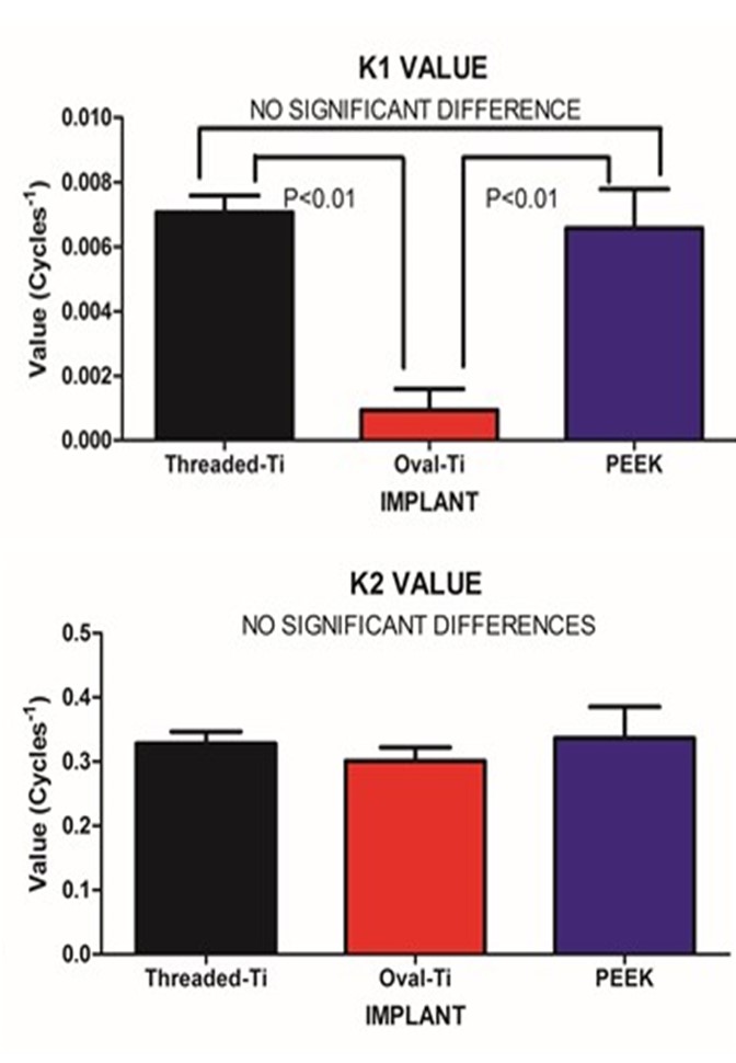 | Figure 6. Fitted stiffness rates (K) for the SLOW (A) and FAST (B) exponential components |
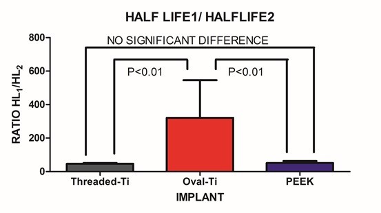 | Figure 7. The ratio of SLOW/FAST components for the fitted Half-lives |
2.3. Discussion
- Under large magnitude loading, the resulting stiffness is primarily confined to the weakest member in the structure. In the case of traditional in-vitro static testing of intervertebral implants, the weakest structure will likely be the vertebral body. While the stronger outer shell of the vertebral body will directly bear the loads transmitted through the implant, it should be recognized that at the mid-sagittal plane, the anterior thickness of the vertebral shell is increased relative to the corresponding posterior and endplate thickness. Such a finding is in agreement with the physiological motion experienced by the spine. The thicker and hence, mechanically stronger central anterior region will bear a greater load under flexion/extension. The endplate and posterior aspects being thinner will permit a level of ductility during loading. Further, the internal pressurization of the vertebral body under both static and dynamic loading is realized through the observance by Silva et al., that the vertebral shell is composed of layers of fused trabecular bone rather than true cortical bone. [17] Such an observation would indicate that internal pressurization is a dynamically regulated process that can be controlled through transport of fluids through the fussed trabecular bone mesh of the vertebral body. Disruption of the internal regulation of the vertebral body pressure by limiting the normal expansion of the outer shell during loading may adversely affect the physiological blood flow within the body and predispose the endplate to detrimental nutrient levels due to altered flow. [18, 19] The net result is that the weaker trabecular bone within the body that will act as pressurized foam in order to aid in loading resistance. [4] This concept was eluded to by Polikeit who employed a finite element model to investigate the effects of intervertebral device insertion upon adjacent segments. While insertion of the device increased the stresses as compared to intact conditions, the alteration in cancellous bone density displayed a profound increase in stress; the more dense the cancellous bone, the greater the stress concentration below the device. [20] Penzkofer et al., found that while implant/endplate contact was important in cases of misalignment, a strong correlation between stiffness and bone mineral density was found (R2=0.82). [21] Stiffness values for a construct comprised of a vertebral body and either a circular or rectangular implant were evaluated by Pekmezci et al. The results indicated that constructs employing a rectangular implant displayed an increased stiffness (1054±329)N/mm as compared to those constructs utilizing a circular implant (473±205)N/mm. The finding suggests that those designs that provide a reduced force per unit area (via increased contact area) and engage the increased mechanical integrity of the vertebral shell will likely display an increased construct stiffness and decreased subsidence rate. [1] This was reflected in the current study in which the Oval-Titanium implant displayed the greatest construct stiffness, or initial stability, and the least overall subsidence compared with the PEEK and Threaded-Titanium implants. While designers of implants should optimize the geometry, clinically, subsidence and stiffness are influenced by bone density, whether it be in the vertebral shell or in the underlying trabecular bone. [2] Both locations play a role in support of the implant. The shell supports the implant through the mechanical integrity of the fused trabecular bone while the porous internal trabecular bone through internal pressurization. The current study represents evaluation of implant performance based on stiffness of the resulting implant/vertebra construct structure under dynamic sub-failure loading. One of the few studies that examined the effects of cyclic loading upon cage designs was conducted by Krammer et al. In that study, a cylindrical threaded titanium cage, a bullet shaped PEEK cage and a rectangular titanium cage with an endplate anchorage device were examined under loading from 200N to 1000N for 40000 cycles at a rate of 5 Hz. Beyond the 100 cycle point, only minor differences in the subsidence tendency for the three cage designs were noted. [22] Large loading amplitudes combined with an increasing number of loading cycles can lead to vertebral failure and hence mask the actual performance of the device under investigation. In contrast, the current study only applied a maximum compressive load of 350N, thereby simulating partial weight bearing as in the early stages of surgical recovery. Under these less demanding loading conditions, the vertebral body can partake in the load resistance and hence the construct stiffness comprised of both implant and vertebral body may be elucidated. At the physiological load levels in this study, this construct load resistance was manifested by a dual exponential fit to the resulting stiffness versus cycle number data. The FAST stiffness rate and associated Half-lives between the three implants was not statistically different. This was to be expected as all three implants display a significantly increased modulus as compared to the underlying trabecular bone. In contrast, the SLOW components depict the gradual settling and strain hardening associated with cyclic loading. Such a condition is not only common to many materials but in the case of bone remodelling, it may be important. Wolff’s Law states that bone will remodel according to the local environment. In the case of the Threaded-Titanium and PEEK implants, the increased SLOW K values (i.e. decreased SLOW Half-lives) will produce a more rapid stiffness increase once the initial settling has occurred. In contrast, the decreased SLOW K value (i.e. increased SLOW Half-life) for the Oval-Titanium implant will permit a more gradually increasing stiffness, thereby allowing more time for adaptation. This was manifested by the SLOW/FAST ratio for the respective Half-lives of each implant. The Oval-Titanium implant displayed a SLOW/FAST ratio that was approximately 7 times greater than the Threaded-Titanium implant and over 6 times greater than the PEEK implant. Such a presentation leads to the concept of a “Landing” of the implant upon the vertebral endplate. In the case of the Oval-Titanium implant, a “Softer” landing after initial deployment is obtained by virtue of the increased SLOW component with respect to the FAST component. In the case of the Threaded-Titanium and PEEK implants a significantly different “Harder” landing is observed as the SLOW component is reduced relative to the FAST component. Using a finite element simulation Wang et al., determined that the structural stiffness of an implant/vertebra construct was weakest immediately following insertion of the implant. In addition, bone remodelling will adapt itself to the changing loading conditions subsequent to the implantation so as to reduce the incidence of subsidence. [23] Based on the fact that the immediate post-operative period is the most mechanically compromised, clinically, the ideal condition would be to engage a “Soft Landing” in order to reduce the incidence of initial subsidence. Work by Ferretti et al, investigated bone formation and resulted in the identification of two mechanisms related to osteogenesis; static and dynamic. [24] In Static osteogenesis, osteoblasts differentiated at a distance of (28±0.4)μm from blood capillaries. Dynamic osteogenesis involved traditional moving osteoblasts across laminae. In addition, it was found that cells from both processes being structurally and ultra-structurally comparable. In summary, static osteogenesis appears to be responsible for the initial layer of bone remodelling. As such, it is weaker woven bone but provides significant numbers of osteocyte lacunae and a stabilizing mechanism that is critical for the initial repair phase of bone healing. It is responsible for increasing the bone ossification center and subsequently bone size. In contrast, Dynamic osteogenesis is accountable for the generation of lamellar bone, resulting in bone compaction and/or thickening of the trabeculae and therefore displays increased mechanical integrity. [25]These two processes can be considered in the context of the SLOW and FAST components for each implant. All three implants behaved comparably at onset as evidenced by the FAST lives on the order of two cycles. This parameter can be thought of as a mechanical settling of the implant upon the endplate. The subsequent SLOW parameters can be assigned to the clinical settling, where changes occur on a significantly longer temporal scale. This secondary phase of settling may be important in static osteogenesis, where distances from the blood supply should remain constant in order to initiate the initial phase of bone healing. The laying down of woven bone, though weak, increases the local moment of inertia and hence imparts an increase in mechanical integrity and stability. The subsequent dynamic osteogenesis will eventually remodel the region and provide the long term stability. In the case of these particular implants, the Oval-Titanium implant displayed the greatest values for the respective SLOW parameters, indicating that it should provide an increased window for static osteogenesis to engage through a reduced rate of stiffening as compared to the Threaded-Titanium and PEEK devices.It is unknown at what point the transition from static to dynamic osteogenesis occurs. It is most likely a gradual transition where static osteogenesis initially dominates followed by a symbiotic transition to dynamic osteogenesis. The SLOW parameters identified in this study may be employed as a time marker to clinically identify the onset of dynamic osteogenesis. Clinically, one may employ mineralization within the bone graft contained within the implant as an indicator for dynamic osteogenesis initiation. With the mineralization time point identified the SLOW parameters fitted in this study may be used as a measure of implant performance as each cycle was applied at 1Hz.
3. Conclusions
- Implant performance cannot be evaluated by a single static failure testing regimen as it does not adequately reflect the oscillatory sub-failure loading that occurs physiologically. This study represents a dynamic evaluation of intervertebral implant performance under dynamic conditions combined with a nonlinear temporal analysis. The resulting analyses revealed that all implants display a FAST and a SLOW component of performance, with all three implants displaying comparable FAST stiffness rates, characteristic of initial mechanical settling upon the vertebral endplate. The Oval-Titanium implant displayed the least SLOW stiffness changes as compared to the Threaded-Titanium and PEEK implants. This reduced stiffening rate may be important in the establishment of static osteogenesis as an initiator of bone healing and stability. An increased SLOW rate with respect to the FAST rate represents a “soft” landing which allows for bone adaptation to occur and may reduce the risk of implant subsidence.
ACKNOWLEDGEMENTS
- This work is the result of a sponsored research grant from: Titan Spine LLC, 6140 Executive Drive, Mequon, WI, USA 53092.