-
Paper Information
- Next Paper
- Paper Submission
-
Journal Information
- About This Journal
- Editorial Board
- Current Issue
- Archive
- Author Guidelines
- Contact Us
American Journal of Biomedical Engineering
p-ISSN: 2163-1050 e-ISSN: 2163-1077
2015; 5(1): 1-5
doi:10.5923/j.ajbe.20150501.01
Simple Technique for Fabricating a Guide Stent for Inclined Implant Placement
Mona M. Elramady1, Magdy A. Awadalla1, Faten S. Mohamed1, Tamer M. Nassef2, 3
1Department of Prosthodontics, University of Alexandria, Alexandria University, Alexandria City, Egypt
2Department of Computer and Software, Misr University for Science and Technology, 6th of October City, Giza, Egypt
3Department of Electronics and Communication, October High Institute of Engineering and Technology, 6th of October City, Giza, Egypt
Correspondence to: Tamer M. Nassef, Department of Computer and Software, Misr University for Science and Technology, 6th of October City, Giza, Egypt.
| Email: |  |
Copyright © 2015 Scientific & Academic Publishing. All Rights Reserved.
The guide stent (also known as a surgical guide) is a plastic jig used by the surgeon to precisely drill the holes for the angulated implant (s) in a predetermined location and/or used for radiographic evaluation during treatment planning for implant placement. It is fabricated in the dental laboratory and should be designed with input from the entire implant team. However, the utilization of surgical stents is imperative for optimum implant installation. This article will describe how a guide stent is fabricated. For accurate placement implants in a definitive inclined position. For each patient maxillary complete denture was constructed and mandibular complete over denture supported by two inclined implants with the help of a fabricated radiographic stent and evaluated by clinical, radiographic, and finite element analysis for each patient. The implant is positioning to be precisely executed, and when safe positioning of implants with optimal use of available bone and save time for surgical work.Keywords Guide Stent, Angulated Implant, Compressive strength, Dental Fabricated
Keywords:
Cite this paper: Mona M. Elramady, Magdy A. Awadalla, Faten S. Mohamed, Tamer M. Nassef, Simple Technique for Fabricating a Guide Stent for Inclined Implant Placement, American Journal of Biomedical Engineering, Vol. 5 No. 1, 2015, pp. 1-5. doi: 10.5923/j.ajbe.20150501.01.
Article Outline
1. Introduction
- The process of making and using a surgical guide stent is intended to enable the surgeon to maintain the same horizontal and vertical axes of cylindrical endosseous implants during the surgical phase of implant placement as those determined at the treatment planning stage. Furthermore, the stent can be used with the entire series of surgical drills, thereby minimizing the chance of inadvertently enlarging the implant site as a result of freehand use of the hand piece. [1] Cylindrical endosseous implants that are correctly located on the edentulous ridge may have an incorrect angulation. [2]Several surgical guide stents have been described in the literature. [3-7] Balshi and Garver [4] described a stent where 2 mm holes are made in an acrylic resin template to act as a guide for the 2 mm pilot drill. Because of its thickness and spacing to allow irrigation, the stent cannot always guide the drill to the full depth of the hole. Once the 2 mm hole has been made, the stent is of little value and the remaining site preparation is done freehand. Furthermore, if an alternative implant location is preferred, the stent cannot be used. The stent described by Edge [5] has drawbacks similar to those of Balshi and Garver. [4] Pare1 and Sullivan [6] and Hobo et a1. [7] described a stent whereby the buccal contours of the proposed implant-supported restoration are created in the stent. The stent does not serve as a direct mechanical guide, and site preparation is done freehand. Engleman et a1. [3] also described a stent similar to that of Pare 1 and Sullivan; however, they suggest that the angulation of the implant site be verified by placing guide pins into the pilot holes with the stent in position.With this technique, the implant angulation (z axis) with respect to the proposed restorations can only be determined after the pilot hole has been prepared.Successful implant treatment is directly related to achieving integration and restoring hard and soft supporting structures for esthetics and function. [3] It is necessary for the clinician to visualize the final prosthetic result before implant placement and to have thorough understanding of the surgical and prosthodontic phases of treatment to achieve a predictable outcome. [8] This desire of predictable results led to development of prosthetically guided implantology. Despite significant advances in devices and techniques, placing dental implants in a correct position still remains a challenge. Diagnostic casts, probing depths and panoramic radiography can lead to unpredictable results as they do not give three-dimensional (3-D) radiographic information required [9-13] for correct positioning and orientation of implant. [3] Moreover, implant supported prosthesis requires determination of final prosthesis during treatment planning stage. Thus for a successful implant supported prosthesis the Prosthodontist should plan the implant position in accordance with accurate mesiodistal and buccolingual location, angulation with residual bone and correct implant orientation. To achieve these objectives dental CT scan imagingincon junction with radiographic guide (stent) with radiopaque marker should be used.Surgical stent provides communication between the surgeon and restoring dentist, so that the implant is placed at the ideal position and angulations The purpose of stent is to preview the definitive restoration and its relationship to adjacent structures, to communicate the restoration planned by the Prosthodontist to the surgeon, to reduce osteotomy and to locate healing screws at the time of second stage surgery. [2] A method of using existing mandibular complete prosthesis as radiographic stent and a duplicated denture as a surgical template. Advantages of the technique are twofold: it is cost effective and makes use of equipment and materials commonly found in dental clinics.Malaligned implants often complicate the clinical and laboratory procedures employed for the fabrication of superstructures. Due to improper load distribution, an overall increase in stress concentrations on supporting implants may occur; in the long run, this may compromise the maintenance of the bone-implant interface. The utilization of surgical stents is imperative for optimum implant installation. A modified surgical stent that serves as a guide to proper mesiodistal paralleling of dental implants. [14]Correct positioning of dental implants is largely dependent on the experience and attention of the surgeon since conventional surgical guides include a single-diameter guide channel that allows only one drill to pass through. [3]Osseointegration of implants is the most important but not the only requirement for a successful implant supported prosthesis. Several studies have demonstrated that an esthetic [4] and functional [5] implant-supported that an esthetic [4] and functional [5] implant-supported prosthesis depends on the optimal placement of osseointegrated implants. Dual-purpose stents can facilitate correct implant placement. [6] Accordingly, implant failure specifically attributed to malangulation is not reported for the anterior maxillary region. The incidence of biomechanical failure increases, however, for implant applications in the posterior region. [15]Non-parallel placement of implants is the primary cause of nonaxial loading during function. Although off-set loading is not the only factor that contributes to the loss of Osseointegration, [16] axial loading of implants should be provided if possible. Conventional surgical stents are frequently and efficiently used for site preparation in most circumstances. However, a simple guide for the arrangement of implant angulation is often missing from stents or templates fabricated as shells.Implant parallelism occurs in both the buccolingual and mesiodistal directions. The buccolingual angulation of an implant often is restricted by the structural form and angulation of the available bone, which may be determined and provided by direct visualization during surgery. [17] However, the mesiodistal paralleling of implants could be ensured with the use of surgical stents provided by prosthodontists. A modification of the conventional surgical stent that will guide the surgeon in parallel placement of implants in the posterior edentulous mandible.There are 2 basic advantages of the perpendicular plane included in the described guide. First, the surgeon can easily place the first implant in the determined angulation by aligning the surgical drill parallel to the reference axis drawn on the perpendicular acrylic plane. Consequently, more implants can be placed mesiodistally parallel to one another with regard to such reference lines traced on the same plane (or with the use of surgical guide pins).Second, the modified design is not a drastic departure from conventional acrylic stents. Complicated stent designs may interfere with site preparation and cause improper implant placement. The one feature added to this modified stent is intended to facilitate ease in the establishment of implant angulation. The perpendicular plane also retracts the mucoperiosteal flap lingually and provides improved visualization during site preparation. Thus, the design is user-friendly.The inability to determine the buccolingual angulation of implants is the primary disadvantage of the modified stent. Buccolingual imaging of the bone with 2-dimensional computed tomography, along with the use of diagnostic stents with radiopaque markers, is the most accurate technique. [18] However, even with this approach, modification of the stent through accurate transfer of the radiographic information is mandatory for surgical purposes. [19]The width and angulation of available bone can serve as a useful and restrictive guide for establishing buccolingual implant angulation. Wide residual ridges that allow various buccolingual angulations for implant placement are uncommon. The high cost, limited availability, and exposure to ionizing radiation associated with computed tomography, [20] in addition to the complicated procedures associated with many dual-purpose stents, all appear less necessary when conventional radiographic techniques can reveal sufficient residual bone dimensions for implant placement.A modification of the conventional surgical stent for mesiodistal implant parallelism has been described. When computerized tomography is not required to evaluate the buccolingual angulation of available bone, the simple design and function of the modified stent make it advantageous for use in the posterior edentulous mandible. Cylindrical endosseous implants that are correctly located on the edentulous ridge may have an incorrect angdation.This study describes a new method to make a surgical guide stent that would enable the operator to maintain the same r, y, and z coordinates of the implant throughout the course of the surgical phase. The use of patient's complete denture prosthesis as radiographic guide after incorporation of radio opaque medium to optimize information from computed tomography scans for implant placement. This article also provides a step by step procedure for duplicating complete denture prosthesis to be used as surgical stent for mandibular implant supported over denture.
2. Materials and Methods
2.1. Study Design
- For each patient maxillary complete denture was constructed and mandibular complete over denture supported by two inclined implants with the help of a fabricated radiographic stent and evaluated by clinical, radiographic, and finite element analysis for each patient.
2.2. Methods
- The prepared Preparation of the stent: The radiographic stent was fabricated to evaluate the implant sites: A Vacuum thermoplastic base plate material was adapted to the mandibululer stone casts. At the desired implant locations –the mandibuler cast was marked by a pencil on the crest of the edentulous ridge.Then again, the locations are marked on the lingual surface of the clear acrylic thermoplastic base plate material using an indelible pencil – corresponding to locations on the mandibuler cast.The locations roughly at canine and first premolar area (each implant were 5 mm anterior to the mental foramen) and the two implants were equidistance to each other.Two small openings 5 mm length and 2.7 mm diameter were drilled in the specified locations on the lingual surface of the stent. Two small metal tubes 5 mm length and 2.7 mm diameter were fixed to the concavities using a clear cyanoacrylate adhesive. The patient wore the thermoplastic stent and the surgen was taken to confirm that the location of the tubes did not interfere with the important mandibular structures. A line was drawn using indelible pencil on the labial surface of the canines of the stent extending from the tip of the canines to the lower surfaces of the cast. According to the natural inclination of the canines which are directed misially toward the mild line. Then a protractor was used to drawn another line which is inclined by15°. A straight hand piece was fixed by special metallic part to be parallel to the vertical arm of the survivor then the cast with the surgical stent is placed on it and the table is tilted to the right and to the left to drill the point of placement of the metallic tubes for the Accurate inclined positional of the implants.After setting, specimens were removed and ground on silicon carbide papers ranging from 650 to 2000. Specimens were inspected visually for discontinuity, voids, cracks and irregularities in ambient light and if present the specimens were discarded.
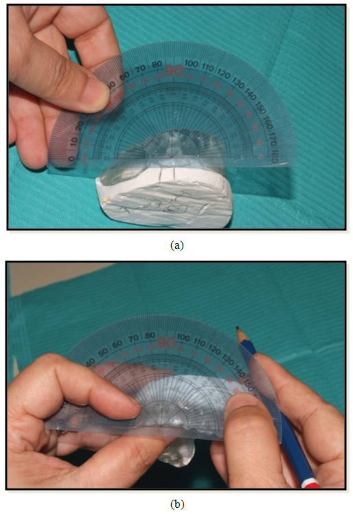 | Figure 1. Indelible pencil on the labial surface to draw the canine lines. Mould used for compressive strength testing |
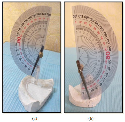 | Figure 2. Simple tool to measure the angle on the model |
3. Results
- Measuring the distance between the inclined implant line at 15° and the mental foramen of all patients of both sides were presented in (Fig.3).
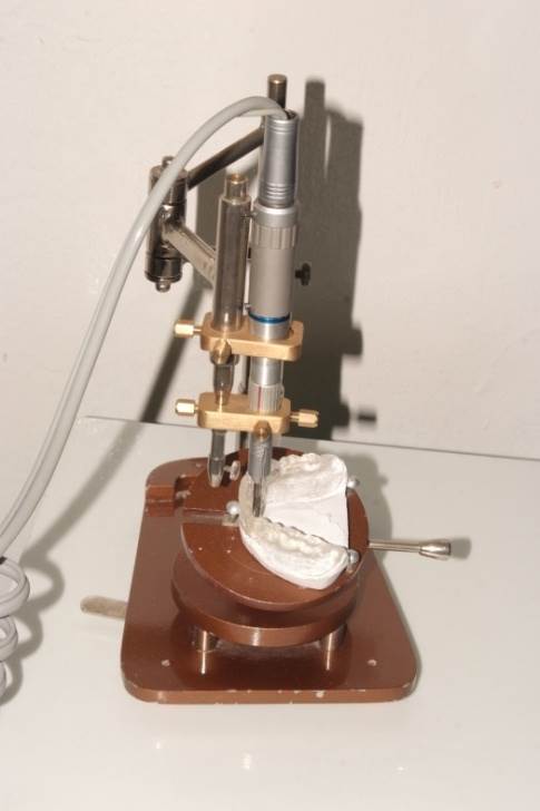 | Figure 3. Specially designed cupper plate with 2 holes and 2 screws attached to the dental surveyor mandrill |
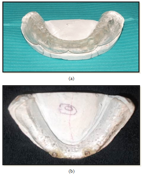 | Figure 4. The surgical stent with two drilled holes for receiving a guiding ring of (2.6mm diameter, 5 mm length which act as a guiding channel) |
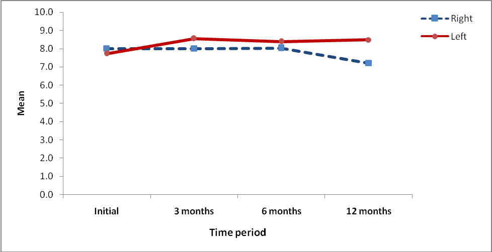 | Figure 5. XRD Mean and standard deviation of the distance between the inclined implant line at 15° and the mental foramen: of all patients of both sides |
4. Conclusions
- The implant is positioning to be precisely executed, and when safe positioning of implants with optimal use of available bone and save time for surgical work. To avoid nerve injury during surgery in the foraminal area, guidelines were developed with respect to verifying the position of the mental foramen.
 Abstract
 Reference
 Full-Text PDF
 Full-text HTML