-
Paper Information
- Paper Submission
-
Journal Information
- About This Journal
- Editorial Board
- Current Issue
- Archive
- Author Guidelines
- Contact Us
American Journal of Biomedical Engineering
p-ISSN: 2163-1050 e-ISSN: 2163-1077
2014; 4(4): 79-87
doi:10.5923/j.ajbe.20140404.02
Growth of Flower-Like Brushite Structures on Magnesium Substrates and Their Subsequent Low Temperature Transformation to Hydroxyapatite
 Abstract
 Reference
 Full-Text PDF
 Full-text HTML
Sridevi Brundavanam, Gérrard Eddy Jai Poinern, Derek Fawcett
Department of Physics, Energy Studies and Nanotechnology, School of Engineering and Energy, Murdoch University, Murdoch, Australia
Correspondence to: Gérrard Eddy Jai Poinern, Department of Physics, Energy Studies and Nanotechnology, School of Engineering and Energy, Murdoch University, Murdoch, Australia.
| Email: |  |
Copyright © 2014 Scientific & Academic Publishing. All Rights Reserved.
Dicalcium phosphate dihydrate (DCPD) Brushite coatings composed of flower-like structures were formed on magnesium substrates via a straightforward chemical immersion technique in order to slow down the corrosion rate of the metallic substrates. Moreover, the synthesised DCPD coatings were also converted to hydroxyapatite (HAP) coating using a low-temperature hydrothermal process to further investigate their ability to reduce the corrosion rate of the substrates in phosphate buffer saline (PBS) and Ringer’s solutions. Degradation studies found DCPD coatings were capable of providing the most significant reduction in the corrosion rate of around 0.100 mm/yr compared to 3.828 mm/yr for the uncoated substrates soaked in Ringer’s solution at 37ºC.
Keywords: Magnesium, DCPD, Hydroxyapatite, Coating, Simulated Biodegradation
Cite this paper: Sridevi Brundavanam, Gérrard Eddy Jai Poinern, Derek Fawcett, Growth of Flower-Like Brushite Structures on Magnesium Substrates and Their Subsequent Low Temperature Transformation to Hydroxyapatite, American Journal of Biomedical Engineering, Vol. 4 No. 4, 2014, pp. 79-87. doi: 10.5923/j.ajbe.20140404.02.
Article Outline
1. Introduction
- Ideally, orthopaedic and dental devices must have a surface chemistry and physical structure that is biological compatible. In addition, they must also induce a positive osteogenic response and avoid any unfavourable immune responses [1]. Biodegradable implant materials currently in use and under development offer many attractive features for a number of clinical applications such as bone fixation, controlled release of pharmaceuticals, endovascular stents and orthopaedic implants [2-4]. The use of biodegradable materials in orthopaedic surgical procedures is of particular interest, since the function of many implants usually comes to an end when tissue regeneration and healing has taken place [3, 5]. The majority of these implants are biologically inert and engineered from metallic materials such as cobalt-chromium based alloys, stainless steels and titanium alloys. Metallic materials are very appealing for load bearing applications due to their ductility, high strength, fracture toughness and anticorrosion properties [6-8]. Typically, many of these implants are only needed for a short period of time to provide the necessary structural and mechanical support during tissue regeneration. However, to remove the implant after tissue regeneration requires a second surgical procedure. The additional surgical procedure is both costly and significantly increases the risk of infection and scarring of the patient [9]. Alternatively, the implant can be left in situ and as a result a number of potentially detrimental effects can take place such as corrosion of the implant material itself, inflammatory responses, stress-shielding and subsequent weakening of surrounding tissues. For example, there can be a significant release of toxic metallic ions such as chromium, cobalt and nickel during biological corrosion and mechanical wear. The production of these toxic metallic ions immediately solicits an unfavourable inflammatory response from the body’s immune system. The unfavourable immune response significantly reduces the biocompatibility of the implant and often leads to secondary revision surgery [10-12]. The other major disadvantage of metallic implants is their superior mechanical properties that are often many times greater than those of natural bone tissues. For instance, cobalt-chromium based alloys can have an elastic modulus that is ten times greater than that of bone and titanium based alloys are typically five times greater [6, 13, 14]. The significant difference between the mechanical properties of the implant and the surrounding bone creates a stress-shielding effect that causes bone resorption and subsequent implant failure. Furthermore, metallic implants are biologically inert and do not biologically or chemically interact with the surrounding tissues. The lack of interaction results in very little interfacial bonding or osteointegration taking place [15]. One currently used technique to improve the osteointegration of metallic implants involves coating them with a bioactive material such as calcium phosphate [16].An attractive alternative to conventional metallic implants is to develop a biologically degradable implant that achieves complete dissolution by the end of the tissue regeneration period [17]. Some successful outcomes have been achieved using biodegradable polymers in applications such as sutures, bone and dental cements, bone grafting materials, plates, screws, pins and fixation devices [18-24]. However, their low mechanical strength means they are only suitable for low-load bearing applications and soft tissue reconstruction. On the other hand magnesium (Mg) is a metallic material with the potential to overcome the limitations of conventional metallic implant materials and degradable polymeric materials. Magnesium offers a number of attractive features such as biocompatibility, biodegradability and mechanical properties similar to bone [25]. The density of Mg is 1.74 g/cm3 at 20℃ and is slightly less than bone which ranges from 1.8 to 2.1 g/cm3. There is also a close similarity between the elastic modulus of Mg (45 GPa) and bone which varies from 40 to 57 GPa [26, 27]. The close similarity of its mechanical properties and its favourable biocompatibility makes Mg a promising material for the development of biodegradable orthopaedic implants [25, 28].Despite Mg many advantages, but its poor corrosion resistance in chloride rich body fluids (pH ranges between 7.4 and 7.6) has severely limited its use in medical applications. The rapid corrosion rate results in two fundamental problems. The first involves the rapid formation of subcutaneous hydrogen gas bubbles that appear during the first week after surgery [29, 30]. However, the bubbles can be drawn off using a subcutaneous needle [31]. The second problem results in the loss of mechanical integrity between the implant and the surrounding bone tissue that prevents effective tissue regeneration. However, this vulnerability to corrosion can be considered as an advantage when designing a biodegradable implant. For example, controlled degradation of the implant will allow natural bone tissues to regenerate and replace the implant [32]. Generally, Mg corrodes in an aqueous environments according to the following equations. The anodic reaction can be explained by the partial reaction expressed in equation (1). While the partial reaction occurring at the cathode can be expressed by equation (2).
 | (1) |
 | (2) |
 | (3) |
2. Materials and Methods
2.1. Materials
- All chemicals used in this work were supplied by Chem-Supply (Australia) and all aqueous solutions were made using Milli-Q® water (18.3 MΩ cm-1) produced by an ultrapure water system (Barnstead Ultrapure Water System D11931; Thermo Scientific, Dubuque, IA).
2.2. Mg Substrate Pre-treatment
- Mg (99.9% pure) sheets were cut into rectangular strips 40 mm in length, 3 mm in width and 0.15 mm in thickness. The strips were polished using 1200 grit silicon carbide (SiC) paper to remove all surface oxides and contaminants. After polishing, the strips were cleaned in a 5 wt% nitric acid (HNO3) solution followed by ultrasonically rinsing in acetone for 10 min. The acetone was then lightly rinsed from the substrates using Milli-Q® water before being allowed to air dry. After drying the weight of each substrate was recorded using an Ohaus PA214C microbalance.
2.3. Substrate Surface Treatment
- The electrolyte used to form the DCPD coatings was prepared by adding 0.32 M of Ca(NO3)2 and 0.19 M of KH2PO4 to 100 mL of Milli-Q® water. The mixture was then thoroughly stirred at 400 rpm for 10 min. The electrolyte was prepared at 25 ± 1ºC and the resulting pH was 4. DCPD coating were prepared by immersing in the prepared electrolyte. Individual substrates were removed from the electrolyte at pre-determined time intervals (3, 15, 30, 60, and 180) so that the size and morphology of the forming coating could be quantified using advanced characterisation techniques. At the end of each immersion period samples were removed from the electrolytic solution, washed in Milli-Q® water, and then allowed to air dry for 24h. Conversion of DCPD coatings to hydroxyapatite (HAP) was achieved by immersing the DCPD coated substrates into a 1M solution of sodium hydroxide (NaOH) at 80ºC for 2h. At the end of this period substrates were removed from the electrolyte solution, washed in Milli-Q® water, and then allowed to air dry for at least 24 h. The HAP coatings were then examined using the advanced characterisation techniques discussed below.
2.4. Corrosion Testing
- The corrosion resistance of coated and non-coated Mg substrates were tested in freshly prepared phosphate buffer saline (PBS) solution and Ringer’s solution. The composition of the PBS solution (in g/L) consisted of 8.006 NaCl, 0.201 KCl, 1.420 Na2HPO4 and 0.240 KH2PO4. The Ringer’s solution composition (in g/L) consisted of 8.6 NaCl, 0.6 KCl and 0.66 CaCl2. 2H2O. The pH of the respective solutions were adjusted to 7.4 and maintained at 37ºC during the corrosion studies to match body fluid pH and temperature. Polarization curves were generated using an EG&G Princeton Potentiostat/galvanostat (Model 273A, supplied EG&G Princeton applied research) configured for a three-electrode experimental set-up. The working electrode in all corrosion tests consisted of a test substrate with a surface area of 1 cm2. A saturated calomel electrode (SCE) was used as the reference electrode and a platinum wire (Pt) was used as the counter electrode. A Tafel test procedure was performed over a voltage range from -2.5 V up to 1.0 V, with a step size of 10 mV and a 1s time interval for the 10 mV scan rate. From the resulting experimentally derived polarization curves parameters such as corrosion potential (Ecorr), corrosion current density (Icorr), anodic/ cathodic Tafel slopes (βa and βa) and corrosion rate were derived. The polarization resistance (Rp) was calculated at the near open circuit potential (OCP) using the Stern–Geary equation:
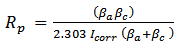 | (4) |
2.5. Advanced Characterisation Techniques
2.5.1. X-ray Diffraction (XRD) Spectroscopy
- XRD spectroscopy technique was used to examine and identify crystalline size and phases present in the surface coating. Spectroscopy data was recorded at room temperature, using a GBC® eMMA X-ray Powder Diffractometer [Cu Kα = 1.5406 Å radiation source] operating at 35 kV and 28 mA. The diffraction patterns were collected over a 2θ range of 20° to 60° with an incremental step size of 0.02° using flat plane geometry with 2 second acquisition time for each scan.
2.5.2. Scanning Electron Microscopy (SEM) and Energy Dispersive Spectroscopy (EDS)
- The SEM technique was used to study the size, shape and morphological features of the surface coating formed on the substrates during the immersion process. All micrographs were taken using a JCM-6000, NeoScopeTM with an attached energy dispersive X-ray spectroscopy function. Samples were mounted on individual substrate holders using carbon adhesive tape before being sputter coated with a 2 nm layer of gold to prevent charge build up using a Cressington 208HR High Resolution Sputter coater.
2.5.3. Transmission Electron Microscopy (TEM)
- The size, morphology and topography of DCPD particles formed were investigated using TEM. Sample preparation consisted removing a portion of the coating from the surface of the substrate. The samples were then placed into small tubes containing Milli-Q® water. The tubes were then sealed and placed into an ultrasonic bath for 10 minutes. The suspensions were then filtered 2 times before a single drop from each sample was deposited onto its respective carbon-coated copper TEM grid using a micropipette. The samples were then allowed to slowly dry over a 24-hour period. After sample preparation a bright field TEM study was carried out using a Phillips CM-100 electron microscope (Phillips Corporation Eindhoven, The Netherlands) operating at 80kV.
2.5.4. Fourier Transform Infrared Spectroscopy (FT-IR)
- FT-IR spectroscopy was used to investigate CaP powders synthesized during the immersion process using a Perkin–Elmer Frontier FT-IR spectrometer with Universal Single bounce Diamond ATR attachment. FT-IR spectra were recorded in the range from 525 to 4000cm−1 in steps of 4 cm-1.
3. Results and Discussions
3.1. XRD Analysis of Calcium Phosphate Formation on Substrates
- Before chemical immersion a representative Mg substrate was examined using the XRD technique [49]. The resulting Mg XRD pattern is presented in Figure 1 (c) and confirms the substrate purity. The XRD pattern also revealed that there was no contamination present on the substrate surface. XRD analysis was also carried out on chemically treated substrates. Figure 1 (b) presents a typical XRD pattern of a substrate after an immersion period of 180 min. Analysis of pattern (b) reveals the presence of a crystalline calcium phosphate phase identified as di-calcium phosphate di-hydrate (DCPD) or Brushite (JCPDS 11-293). No other calcium phosphate phases were found in the samples. However, the XRD analysis did confirm the presence of Mg peaks (002), (101) and (102) produced by the underlying substrate. The coating produced during immersion was formed via the following reaction [9, 48]:
 | (5) |
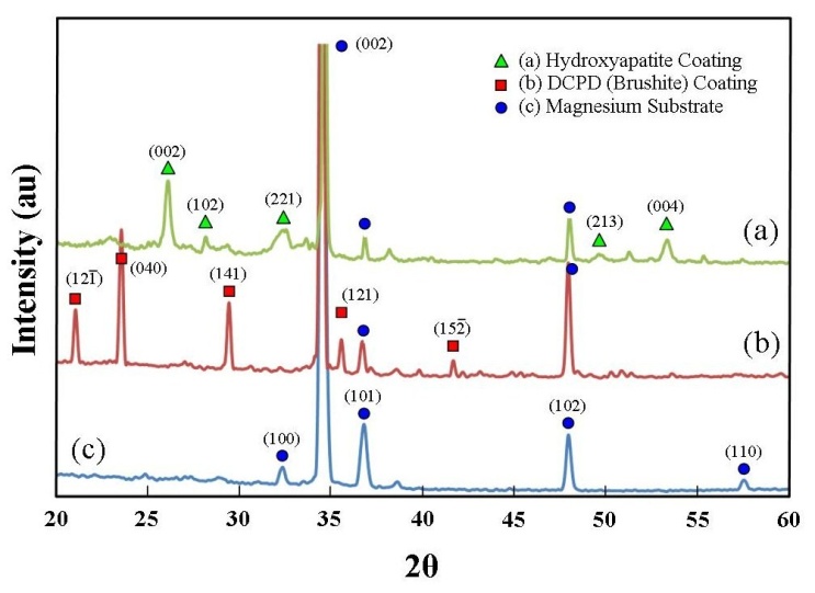 | Figure 1. XRD patterns for uncoated and coated substrates: (a) hydroxyapatite coating converted from a DCPD coating; (b) DCPD coating, and (c) pure magnesium substrate |
3.2. SEM and EDS Analysis of Coating Formation
- The size, morphology and topographical features of the deposited DCPD coatings were examined using SEM and the composition of the coatings were investigated using EDS spectroscopy. Figure 2 presents a series of SEM micrographs taken during the formation of a typical DCPD coating at immersion periods of 3, 15, 30, 60, and 180 min. Figure 2 (a) is a micrograph of a representative Mg substrate prior to chemical immersion. Micrograph 2 (b) was taken after a 3 min immersion period. The image reveals the presence of scattered individual small DCPD plate assemblies that are typically around 50 µm in size. After 15 minutes the scattered plate-like assemblies are beginning to grown into flower-like features. At this point in time the features are around 150 µm in size as seen in Figure 2 (c). For an immersion period of 30 min, the flower-like features have grown in size and are starting to merge with nearby neighbours as seen in Figure 2 (d). Also clearly visible at this stage were large areas of exposed underlining substrate. Following a further 30 minutes of immersion, the flower-like features completely cover the substrate surface as seen in Figures 2 (e) and 3 (a). An enlarged view of the flower-like petals is presented in Figure 3 (b), while Figure 3 (c) presents a detailed end view of the petals showing their plate-like structure. Typically, at the end of a 180 min immersion period substrates were completely covered with large flower-like features typically around 500 to 700 µm in size as seen in Figure 2 (f).
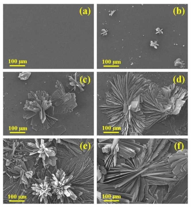 | Figure 2. (a) Cleaned magnesium substrate and subsequent formation of DCPD coating after electrolyte immersion periods of (b) 3; (c) 15; (d) 30; (e) 60, and (f) 180 min |
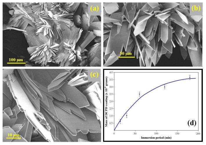 | Figure 3. (a) DCPD (brushite) coating decorated with ornate flowers covering the entire substrate surface; (b) enlarged view of flower petals; (c) detailed end view of DCPD crystal plates forming the petal structure, and (d) mass of DCPD coating formed with increasing immersion periods |
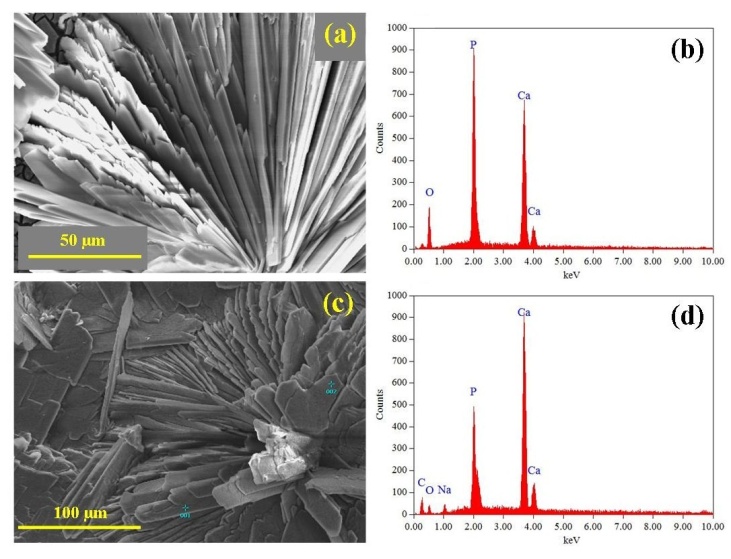 | Figure 4. (a) a representative SEM micrograph of a DCPD flower decorating the coating; (b) EDS analysis of the flower showing its elemental composition; (c) a typical SEM micrograph taken after the conversion to form HAP, and (d) EDS analysis of the coating after conversion |
3.3. FT-IR and TEM Analysis of DCPD Formation
- Analysis of the FT-IR spectroscopy data was carried out to identify species, functional groups and vibration modes associated with each peak of the DCPD and HAP coatings. Figure 5 presents the results of the FT-IR analysis. Conversion of DCPD to HAP was confirmed by the appearance of a peak located at 601 cm-1 that corresponds to PO43- functional groups normally associated with HAP and not DCPD. TEM analysis of the DCPD coatings revealed that they were composed of plate-like structures that were configured in a flower-like feature. A TEM image of a single DCPD plate taken from a representative coating is presented in Figure 6 (a). Its appearance is solid, angular and typical of DCPD structures seen in the coatings. However, after chemical conversion the appearance and structure of the coating dramatically changes as seen in Figure 6 (b). The solid plate-like structure are transformed into a completely different morphology composed of HAP.
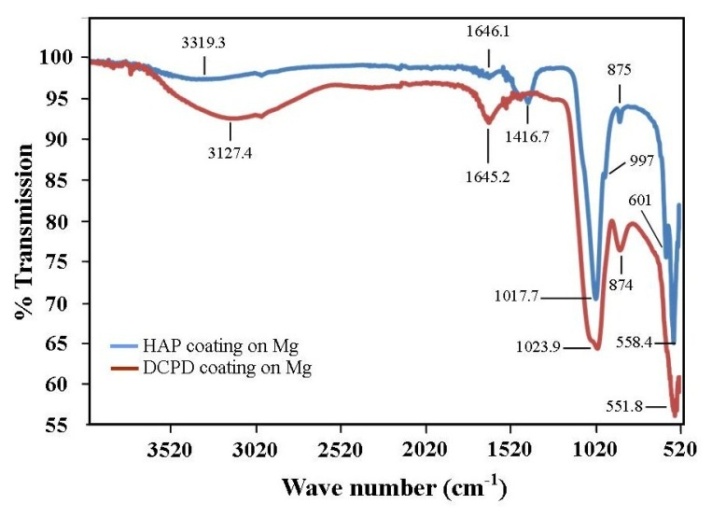 | Figure 5. Results of FT-IR analysis showing the presence of PO43- functional groups at peak position 601 cm-1 characteristic of HAP formation |
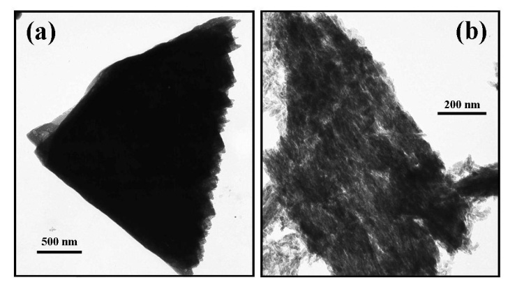 | Figure 6. TEM images taken before and after conversion: (a) a typical plate-like structure associated with DCPD coating, and (b) a typical HAP structure seen after the conversion process |
3.4. Corrosion Resistance of Coatings
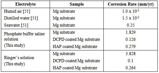
- To be an effective biodegradable material an Mg based implant must slowly degrade and allow regenerating bone tissues to progressively take over from the load carrying function of the implant. To achieve this objective the corrosion rate of the Mg implant must be effectively controlled and allow sufficient time for successful tissue regeneration to take place. Furthermore, by effectively controlling the corrosion rate of a biodegradable implant means that it is possible to avoid the long-term complications normally associated with conventional metal implants. This study has examined the performance of two CaP coatings in reducing the effects of corrosion on Mg substrates in PBS and Ringer’s solutions at 37ºC. Representative potentio-dynamic polarization curves produced by the corrosion tests for Mg substrates with and without CaP coatings are presented in Figure 7. Figure 7 (a) presents the PBS solution test results and clearly show a significant improvement in corrosion resistance of coated substrates. The DCPD coating provided the superior corrosion resistance compared to the HAP coating. The calculated corrosion rate for DCPD coatings were found to be 0.126 mm/yr and was a significant improvement over the 1.829 mm/yr for the uncoated Mg substrate. Importantly, the corrosion rate of the DCPD coating was half the value found for the equivalent HAP coating as seen in Table 1.
|
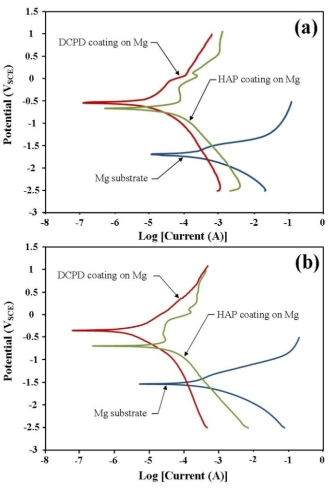 | Figure 7. Polarization curves produced during the corrosion tests carried out in (a) Phosphate buffer saline (PBS) solution and (b) Ringer’s solution for both DCPD and HAP coated magnesium substrates |
4. Conclusions
- The corrosion rate of Mg substrates in PBS and Ringer’s solutions at 37ºC was significantly reduced by the presence of a DCPD or HAP coating. The initial DCPD coatings were formed via a straightforward chemical immersion technique. The coatings were subsequently converted to HAP via a low-temperature hydrothermal process in order to examine which coating had the most effective corrosion resistance. FT-IR analysis was used to confirm DCPD conversion to HAP. Corrosion studies revealed that DCPD coated substrates had the lowest corrosion rate in both PBS (0.126 mm/yr) and Ringer’s solution (0.1 mm/yr) compared to HAP coated and uncoated Mg substrates. Both DCPD and HAP coatings have the capacity to significantly reduce the corrosive effects of PBS solution and Ringer’s solution. Since both these solutions are similar in nature to body fluids, the corrosion studies suggest that both coatings have the potential to reduce similar corrosive effects found in the body environment. However, further in vivo studies are needed to fully study and quantify the corrosive effects of actual body fluids on DCPD and HAP coatings formed in this study. This is of particular importance since Mg based degradable implants with DCPD and HAP coatings offer the potential to significantly improve biocompatibility and promote bone formation during tissue regeneration in hard tissue trauma treatments.
ACKNOWLEDGEMENTS
- The authors would like to thank Mr Ken Seymour for his assistance with the XRD measurements and Associate Professor Gamini Senanayake for his assistance with the electrochemical measurements.