-
Paper Information
- Previous Paper
- Paper Submission
-
Journal Information
- About This Journal
- Editorial Board
- Current Issue
- Archive
- Author Guidelines
- Contact Us
American Journal of Biomedical Engineering
p-ISSN: 2163-1050 e-ISSN: 2163-1077
2014; 4(2): 41-52
doi:10.5923/j.ajbe.20140402.03
A Smoothed Particle Hydrodynamics Approach to Simulation of Articular Cartilage
 Abstract
 Reference
 Full-Text PDF
 Full-text HTML
Philip Boyer 1, Chris Joslin 2
1Department of Systems and Computer Engineering, Carleton University, Ottawa, K1S 5B6
2School of Information Technology, Carleton University, Ottawa, K1S 5B6
Correspondence to: Philip Boyer , Department of Systems and Computer Engineering, Carleton University, Ottawa, K1S 5B6.
| Email: |  |
Copyright © 2014 Scientific & Academic Publishing. All Rights Reserved.
A practical preoperative simulation of femoral acetabular impingement (FAI) requires a faster method than is currently available to simulate the articular cartilage within the hip joint. Articular cartilage has been extensively studied with finite element methods (FEM), and several models have previously been developed to simulate its complex material behaviour. In the present study, the fibril-reinforced poroviscoelastic model was extended to function in a smoothed particle hydrodynamics (SPH) simulation. Four indentation tests and one unconfined compression test were designed and validated with previously published experimental reaction force results. 3D models were visualized to identify areas of peak stress and component stresses during simulations. Strong correlation in reaction forces (r=0.98~0.99) was found between simulations and published results. 3D models displayed stress distributions indicating correct component behaviour. The fibril-reinforced poroviscoelastic models were found to perform with greater accuracy than the hookean models while requiring a mean frame rate drop of only 29% (standard deviation 0.62%). Simulations functioned at rates exceeding 100 frames / second.
Keywords: Articular cartilage mechanics, Smoothed Particle Hydrodynamics (SPH), Porous flow, Solid deformation, Compression
Cite this paper: Philip Boyer , Chris Joslin , A Smoothed Particle Hydrodynamics Approach to Simulation of Articular Cartilage, American Journal of Biomedical Engineering, Vol. 4 No. 2, 2014, pp. 41-52. doi: 10.5923/j.ajbe.20140402.03.
Article Outline
1. Introduction
- Femoral acetabular impingement (FAI) is a medical condition in which abnormal bony protrusions on the femoral head or the rim of the acetabulum produce stress concentrations in the hip joint during motion. Damage incurred in the articular cartilage due to the increased stress in impinged areas is thought to be a precursor to cartilage degeneration and osteoarthritis [1, 40]. A preoperative simulation of real patient hip morphology that could be manipulated during the planning of procedures would be of great benefit to surgeons and could also conceivably reduce the necessity for total hip arthroplasties if the FAI is indentified early.Articular cartilage is an essential component to any such simulation despite a thickness not greater than 4 mm [1, 29]. It is a biphasic soft-solid tissue comprised of an interstitial fluid phase and a solid matrix that interact to distribute and dampen the load carried by a joint. Significant progress has been made towards the accurate simulation of articular cartilage with computational methods, beginning with the biphasic theory of Mow et al. [29]. Mak et al. [25] extended this to the biphasic poroviscoelastic (BPVE) model with fluid flow-dependent and independent parameters to simulate viscous effects. Both the transverse isotropic model [1, 9] and the conewise elasticity model [38] provide means of including directionality in loading response. Soulhat et al. [39] proposed the more rigorous approach to the simulation of cartilage fibrils, which was subsequently extended by Li et al. [21, 23] to the biphasic fibril-reinforced poroelastic model. It is beyond the scope of this paper to provide a thorough review of the field of cartilage simulation, but other significant works include those by DiSilvestro [9], Korhonen [18], Wilson [42], Garcia [13], and Seifzadeh [33], to name only a few.The finite element method (FEM) is the traditional means of modeling articular cartilage. While FEM is considered to be the gold standard for accuracy in computational methods, it is an unrealistic expectation that with the current technology included in a reasonable desktop PC that FEM could be made to perform interactively in a preoperative simulation considering the many nonlinear properties of articular cartilage. Other methods have been proposed for the simulation of soft tissue, perhaps the predominant of which is known as mass-spring [36, 1, 28]. However, mass-spring is impractical for the intended FAI simulations, since it is a non-volumetric method where spring elements connecting point masses must be tuned for each desired scenario [1, 44]. Smoothed particle hydrodynamics (SPH) is a Lagrangian particle technique that employs a nearest neighbour search to reduce the computational complexity of a simulation. While SPH was originally developed for the simulation of exploding celestial objects [14], considerable work has since been performed with fluid dynamics simulations of the Navier-Stokes equations [30, 6]. SPH has more sparingly been applied to solids, beginning with the work of Desbrun and Cani [11], and extended to bending, fracturing, and high impact tests [15, 7, 5]. Solenthaler et al. [37], provided an approach to derive the deformation field of an elastic solid, which was improved upon by Becker et al. [4] by a corotation method to prevent unrealistic forces in rotations. Porosity in an elastic solid material using SPH was proposed by Lenaerts et al. [20]. The recent work by Akinci et al. provided means to combine the simulation of solid and fluid SPH [1]. The extension of SPH to soft tissue is relatively sparse, with a few examples of fluid SPH confined by mass-spring meshes [31, 32], and a simulation of a virtual liver by Hieber et al. [17] that was limited to small deformations in two dimensions.The research presented here uses SPH to simulate articular cartilage as a biphasic fibril-reinforced poroviscoelastic material employing a combination of components drawn from previously published research and newly introduced methods. The objectives were to implement such a model and validate it using indentation and unconfined compression tests while considering the necessity of computational efficiency as applicable to a future real-time hip simulation.
2. Materials and Methods
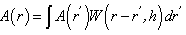
- The fundamental SPH integral interpolant is given by Gingold and Monagahan [14] in its generalized form as:
 | (1) |
 is the function of the spatial coordinates
  ,
,  is the smoothing kernel, and
  is a differential volume element. The integral is advanced in time for each particle using an integration technique, which in the current work is the commonly used leapfrog method. The continuum of a material can be represented by Lagrangian SPH particles with physical equations based upon the above interpolant.In the current procedure, the behaviour of articular cartilage in response to compression scenarios is considered to be due to the interactions of the stresses in each of the components:
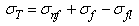 | (2) |
 is the total stress from all components, while
  ,
,  and
and  are respectively the stress contributions from the non-fibrillar solid matrix, the collagen fibril network, and interstitial fluid support.
2.1. Non-fibrillar Matrix
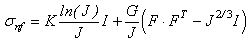
- The model used to represent the non-fibrillar matrix component of cartilage is based upon the works by Solenthaler [37] and Becker [4]. This model was extended to perform all computations in parallel using Nvidia’s CUDA framework and was tested to verify that it exhibited correct rotational behaviour. Since the underlying method remains the same as proposed in the aforementioned papers, for brevity it will not be repeated here except where specifically relevant to new components (in particular please refer to these papers for force evaluation in the solid matrix). One particular such case is that of the hookean constitutive material model, which has been replaced in the current research by the non-linear elastic neo-hookean model suggested by Wilson et al. [43]:
 | (3) |
 is the determinant of the deformation tensor
  . The deformation tensor follows directly from the calculations to obtain the strain in the elastic solid equations of Solenthaler et al. [37], with the addition of the identity tensor, yielding the relation:
 | (4) |
 | (5) |
 | (6) |
 is the Young’s modulus and
  the Poisson’s ratio.
2.2. Collagen Fibril Network
- Collagen fibre placement within the material is simplified with the assumption that a fibre is created between every particle and each of its neighbours, which in the case of the current tests are arranged in a regular lattice. There is a precedent for establishing fibre location according to element spacing [16]. This allows for the stress response of fibres to be modelled by the deformations and displacements affecting particle neighbourhoods rather than explicitly creating particles for their representation. The number of fibres differs depending on the particle position in the object volume.The strain
 in each fibre is determined by:
 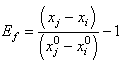 | (7) |
 and
and  represent the positions of particle i and its neighbour j, while the superscripts of 0 indicate the initial underformed positions. It is assumed that fibres only strengthen the material in tension so only positive strains are considered. Fibres are modelled as linear springs with stiffness
  in parallel with a nonlinear spring with stiffness
  as in the work by Li et al. [21], where
  and
and  are the modulus and strain of the fibre, respectively. Even without viscoelastic properties this is assumed sufficient to capture the behaviour of the fibril network for the current research. Viscoelastic effects in fibres could not be implemented at this time due to numerical precision constraints.In real cartilage tissue, fibre orientation is depth dependent, which as is typically assumed in FEM simulations to be 0° to the articular surface in the superficial zone (0% - 10% of depth), 45° in the middle zone (10% - 70% of depth), and 90° in the deep zone (70% - 100%). This is the depth dependency assumed for the current simulations. Individual fibre contribution to the stress profile can be found via a relationship between the particle orientations and the assumed fibre angle. Because the particle neighbourhoods and their associated fibres may have changed orientation, the new assumed fibre angle for the current particle’s zone is found by:
 | (8) |
 is the current assumed fibre angle,
  is the original undeformed assumed fibre angle, while
  and
and  are the current and undeformed angles between the particle and its neighbour. This leads to a multiplication factor M defined by:
 | (9) |
 | (10) |
2.3. Interstitial Fluid
- The behaviour of interstitial fluid through the porous structure of the non-fibrillar matrix is based upon the work by Lenaerts et al. [20] but has been significantly adapted to conform with the needs of the current research. Each SPH particle begins the simulation with an associated fluid mass that can then be exchanged between neighbouring particles and the external environment. The expression for the saturation of the material is given by Lenaerts et al. as:
 | (11) |
 is the absorbed mass of the fluid in particle ,
  is the fluid density,
  is the particle porosity, and
  the particle’s current volume, which is calculated as by Solenthaler et al. [37]. In the work by Lenaerts et al., the porosity was calculated based on the changing fluid density, but it is suggested here that it is beneficial to base the porosity on the changing fluid volume:
 | (12) |
 is the initial porosity of the current particle, is the current porosity, and
  is the initial particle volume. Now if the ratio of the current volume to the initial volume is reduced to equal the initial porosity of the material (0.5 for example), the porosity will also become equal to zero, simulating all the fluid mass exiting from that porous particle. This is essential for the simulation of cartilage since when all the fluid is exuded from the material the load should be entirely borne by the non-fibrillar matrix and collagen fibrils.Depth dependency of porosity is incorporated into the current procedure by:
 | (13) |
 is the depth dependent porosity,
  is a material constant,
  is the height of the sample and
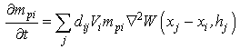
  is the current particle depth.The absorbed fluid mass is dependent on the fluid density by the relation:
 | (14) |
 of the bulk material must be updated to reflect the additional fluid component to the solid component
  for use in the equations defining the non-fibrillar matrix:
 | (15) |
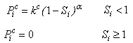
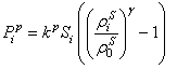
 acts to draw fluid into a porous material via surface tension, while the pore pressure
  can cause fluid to flow into or out of the material depending on the saturation.
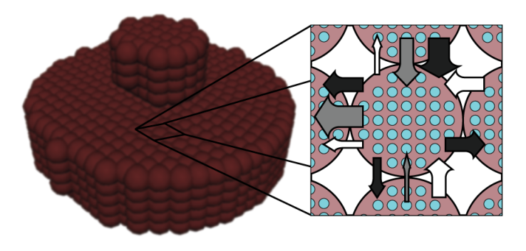 | Figure 1. Example fluid mass exchange between SPH particles. Black arrows represent pore (blue) pressure, white arrows represent capillary pressure, grey arrows represent resultant fluid flow between effective solid particle volumes (brown) |
 | (15) |
 | (16) |
 is again a user-controlled constant,
  and
and  are the current and original densities, and
  is a user-controlled constant to enforce incompressibility.The pore velocity
  , the rate at which the fluid mass is diffusing, is changed from the work of Lenaerts et al. so that it is more intuitively based on the difference in capilllary and pore pressure between a particle and its neighbours. This allows for the relationship to be reduced to a single equation:
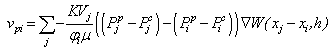 | (17) |
 is the permeability of the material,
  is the viscosity of the fluid, and
  is the SPH kernel employed in the work by Solenthaler [37]. The permeability can be made strain dependent by the relation [43]:
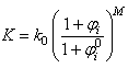 | (18) |
 is the initial permeability,
  is a positive constant, and
  and
and  are the initial and current porosity.Fluid SPH particles are never explicitly created in the simulation, so fluid mass is exchanged in the material in a Eulerian manner defined by the differential:
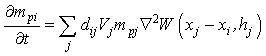 | (19) |
 is a scalar that is the result of a scalar product between the pore velocity and the unit vector of the neighbour-to-current particle direction, ensuring appropriate contributions to the mass exchange by each neighbouring particle:
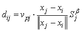 | (20) |
 is a user-defined constant to control diffusion, noting that in the current procedure this will have an additional effect to that originally intended by Lenaerts et al. in that it will increase diffusion with saturations greater than 1. An explicit Euler integration is performed during the update section of each time step to diffuse the fluid mass:
 | (21) |
 | (22) |
 is a user-defined constant, as in Lenaerts et al.Since the concern in the current research is only with the cartilage behaviour, it is not necessary to explicitly create SPH particles representing exterior fluid mass. This was accomplished through the creation of so-called void particles, which are essentially containers of infinite size with which the mass from the cartilage particles can be exchanged. They are instantiated in space according to the original particle positions as shown in Figure 2.Void particles are only considered in two neighbour loops within the simulation. The first is during the calculation of equation 17, which for void particle neighbours becomes:
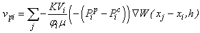 | (23) |
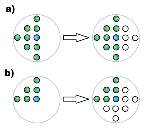 | Figure 2. Void particle instantiation: The current particle position (blue) and the positions of its neighbouring particles (green) are checked to determine where void particles should be placed (white) |
 | (24) |
2.4. Rigid Body Boundary Enforcement
- Cartilage compression simulations require the creation of rigid materials to represent indenters and plates that can be used to cause deformation in the material, or for bone in the case of a whole hip joint simulation. This is accomplished here by the virtual particle method [24], which employs boundary particles along the surface of any rigid object with two layers of virtual particles for neighbourhood support. Pressure forces exerted by boundary particles on any cartilage particles that enter their sphere of influence are calculated according to the SPH fluid pressure force calculations [27] using Desbrun’s spiky kernel [10]:
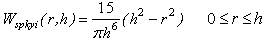 | (25) |
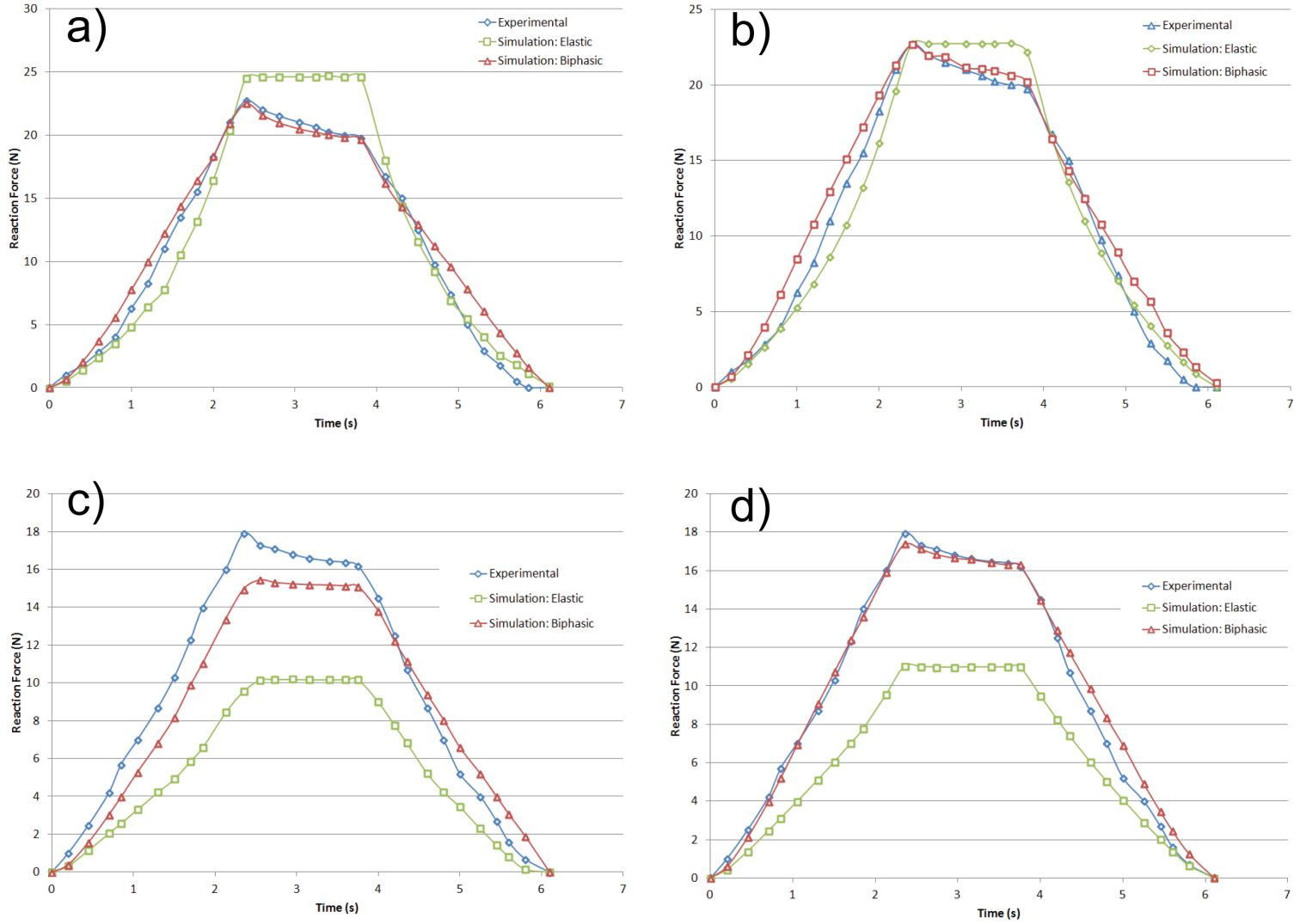
2.5. Simulation Parameters
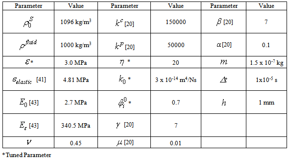
- Simulations were performed on an Intel Core i5-3450 CPU with 8GB of RAM and an NVIDIA GeForce 660Ti with 2GB of memory. The C++ program created to perform the simulations was divided into an initialization section with a combination of host and CUDA code, and a main loop that was run each time step with all associated calculations performed in parallel using CUDA. Visualizations were created in the Maya 2013 API through direct correlations to the output of particle positions from the C++ program. Four indentation tests and one compression test were performed to confirm validity. A minimum of two simulations were run for each test, corresponding to a perfectly elastic material model and the proposed biphasic fibril-reinforced poroviscoelastic material model. Indenter tests were prepared to match the complete femoral knee compartment experiments of the female subjects of Vidal-Lesso et al. [41] as closely as possible (for more complete subject details refer to that paper). The compression test was similarly based upon the highly regarded FEM work by Li et al. [22]. These experiments and simulations were chosen due to restrictions on stability within the simulation. Because the stability is based upon the deformation of the non-fibrillar matrix, the fluid mass is currently not able to support in excess of 20% of the load. However, by increasing the permeability of the material (3 x 10-14 m4/Ns versus 1.522 x 10⁻¹⁵ m4/Ns of Wilson et al. [43]), short time relaxation to match the published results can be achieved via faster diffusion (i.e. the solid matrix component is stiffer but fluid diffuses more quickly, thereby decreasing the stiffness of the bulk material at a rate approximating the literature at short time spans). A Poisson’s ratio of 0.45 was selected to simulate near-incompressibility.Indentation tests 1 and 2 were created to match specimen 1 of the work by Vidal-Lesso et al. [41], with a cartilage depth of 2 mm corresponding to a 5 particle thickness. Indentation tests 3 and 4 were created to match specimen 5 of the work by Vidal-Lesso et al. [41], with a cartilage depth of 3 mm corresponding to a 7 particle thickness. The cartilage thickness is constrained to the 1/2 mm initial particle spacing. Tests 1 and 3 were created as circular plugs 8 mm in diameter, while tests 2 and 4 were squares with 12 mm to each side. Creating both circular plugs and larger squares for similarly constrained simulations - with the larger squares having a greater similarity in surface area to the cartilage experiments of Vidal-Lesso et al. - allows for analysis of the effect of surface area on the simulations. In all indentation tests a circular indenter of 3 mm diameter applied a constant strain rate of 0.21 mm/s (as given in the above work; 0.07%/s strain rate equivalent) to achieve 0.5 mm displacement, followed by a relaxation period of 1.5s, and then an unloading period at the same rate. The compression test was similarly created to match the FEM work of Li et al. [22], where unconfined compression creates a 15% strain over a 15s period on a 3 mm diameter plug followed by 15s of relaxation. In this case, the simulations were not intended to be capable of mimicking the relaxation phenomena of the longer time span of that simulation. Rather, the concern was instead that the reaction force match their results at peak strain, thereby validating the simulation procedure for a second type of scenario in addition to the indenter tests.
|
3. Results and Discussion
- Figure 3 provides a visualization of Indenter test 4, which is the largest of the simulations with 6696 particles, and as such provides the most clarity for evaluation. Stress is represented as the average of the magnitudes of the principal stresses with increased brightness representing increased stress. At maximum strain (Figure 3b) the stress is concentrated around the area of the indenter, which over the following 1.5s spreads outward from that region due to the diffusion of fluid mass (Figure 3c). When the indenter is removed from the cartilage (Figure 3d), the material exhibits an area of low stress where the indenter had been because of lower fluid content, yielding a corresponding negative pore pressure.
 | Figure 3. Visualization of stresses in the particle system representing the cartilage in indenter test 4: a) t = 0s, b) t = 2.38 s, c) t = 3.88 s, d) t = 6.26 s |
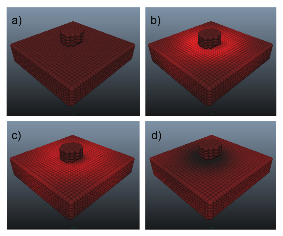
 | Figure 4. Visualization of component stresses at peak strain in indenter test 4: a) fibril stress, b) pore stress |
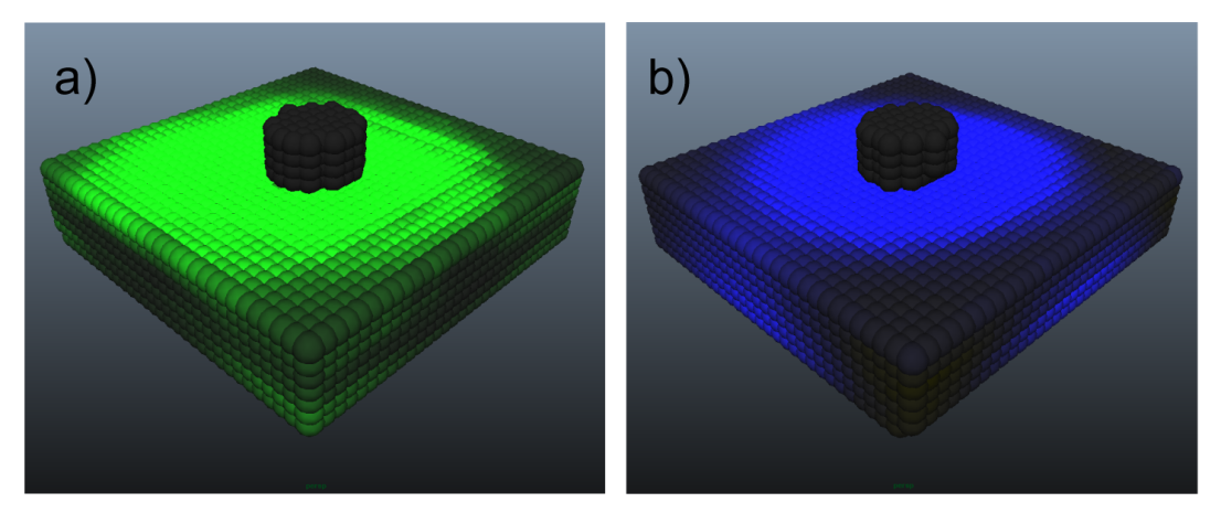
 | Figure 5. Indenter reaction force for biphasic and elastic simulations versus experimental [41]: a) Indentation test 1, b) Indentation test 2, c) Indentation test 3, d) Indentation test 4 |
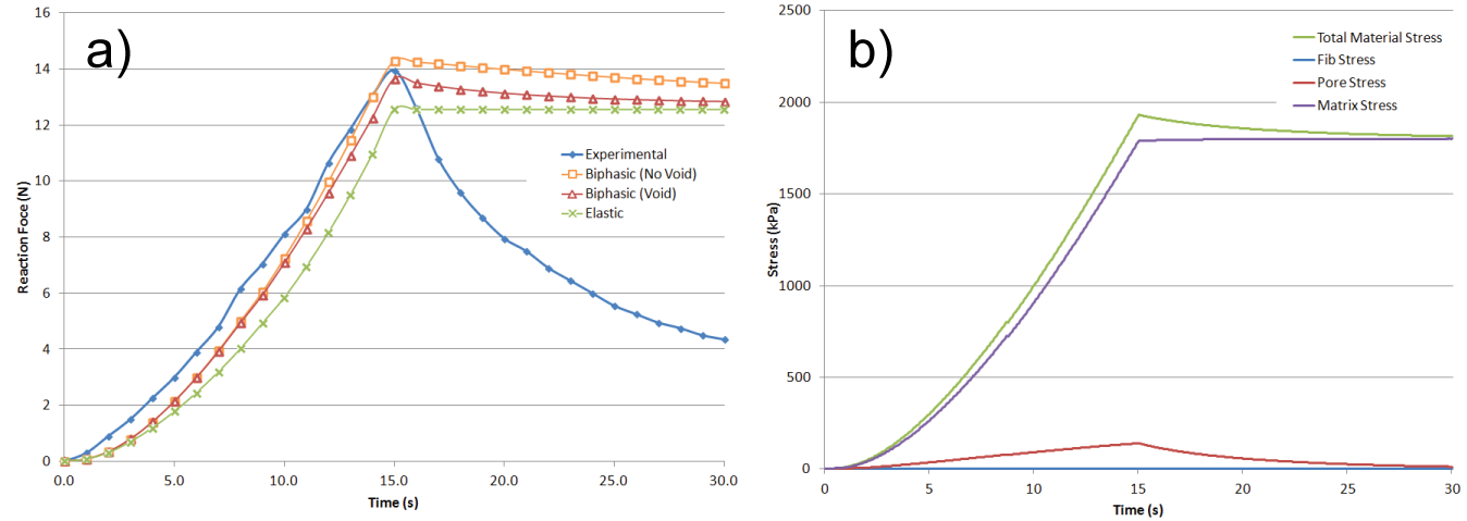 | Figure 6. Unconfined compression simulation results: a) Reaction force of elastic and biphasic (with and without void particles) simulations versus FEM results of Li et al. (“experimental”) [22], b) Component stress contributions and the total material stress |
4. Conclusions
- A new method has been presented to simulate articular cartilage in indenter and unconfined compression scenarios using SPH. Biphasic fibril-reinforced poroviscoelastic simulations produced superior results to Hookean material models in all cases. The decrease in frame rate of 29.03% (with standard deviation of 0.62%) is considered to be acceptable for the attained increase in accuracy. This may also be the first solid SPH simulation that is capable of producing accurate reaction force results to deformations.The stability requirements of the simulations placed restrictions on the available research that could be used for comparison, since the vast majority of published results are focused on long-time compression rather than the short-time scenarios presented here. However, short time compression is likely more relevant to FAI since peak stresses occur during motion where articular cartilage does not demonstrate long term relaxation phenomena. While the tuned parameters from indentation test 1 produced strongly correlated results in all subsequent tests, in the ideal case the stiffness and permeability parameters should be based on results determined through investigation of real cartilage samples. Increasing the stability of the simulations, in particular the fluid mass exchange, is therefore a primary concern with this procedure, but this cannot be accomplished by limiting particular variables since the fluid load support needs to be as high as possible to achieve closest approximations to experimental results. To alleviate this problem, an alternative to the simple leapfrog approach to integrating the particles of the solid portion of the material is suggested to be the next avenue of research, although it would have to be determined how to propagate the fluid flow in the material in this case, since it is currently performed in a Eulerian manner.Unlike in the case of the indentation tests, it was unclear how to represent localized stresses in the unconfined compression test other than with the method of division over the surface area of the material that was used by Li et al. This is largely due to the current lack of a means to reduce all of the extremely complex interactions of the components to a single stress value that is relevant throughout the bulk material.The lack of friction in the simulation is a concern that needs to be addressed. Specifically, it was necessary to restrain the bottom layer of the plugs from lateral movement otherwise the entire pieces would slide out from beneath the indenter without causing deformation. However, it should be noted that due to boundary lubrication and other mechanical effects, the real interaction between cartilage surfaces in a joint is nearly frictionless.The simulations were validated against knee compartment indentation experiments and FEM compression simulations found in the literature. In the future, “short time” experiments (as opposed to the 100 ~ 1000 second experiments that comprise the majority of published work) on articular cartilage extracted from the hip joint to determine material parameters and behaviour would provide a more suitable basis for validation. However, it is thought that the studies used for comparison in this work provide sufficient accuracy.The four tuned parameters as indicated in Table 1 above were found to be essential to the stability of the simulations. They were determined by a rigorous trial and error methodology that arrived at the values given that allow for the full range of material behaviour presented in the works of Vidal-Lesso et al. experiments and Li et al. simulations to be reproduced. Therefore it is highly recommended to use these same values in the reproduction of this work until the stability issues can be resolved. Nevertheless, although these parameters are not analogous to their real material equivalents, the material behaviour, suggested here to be a far more relevant consideration to a preoperative simulation of impingements, matches that expected of cartilage.CUDA was found to have a 1.5X to 2.4X increase in computational speed over host code in these simulations. However, although the frame rates presented in Table 2 could be argued to be interactive, they do not represent a real-time simulation. It was found to be necessary due to the high material stiffness to decrease the time step corresponding to each frame to an extremely small size. It is thought that an improved integration method could also allow for a significant increase in time step size. There is currently a 60,000 particle limit in the simulation, which was sufficient for the current simulations. However, a simulation of a complete hip joint for preoperative purposes may require significantly more particles than this. Since this limit was found to be directly relatable to the amount of onboard memory of the GPU (an investigation not shown in this paper), this limit could be increased by the use of a more powerful video card than the 2GB card used for the current simulations. Alternatively, it may be possible to devise a method of sending the particle data in batches to the video card to be operated upon rather than in bulk.An important adjustment to the visualization of the simulations that needs to be made in the future is to provide a stress magnitude correlation to the displayed colour. Currently, the colourization is only provided for analysis of general trends, and actual stress values are determined from internal investigation of the resulting numerical values of individual particles. Such an adjustment would make the simulations much more pleasant to analyze. Nevertheless, the visualization in its current state does not detract from the accuracy of the reaction force results.It is suggested here that the current research has reached a level of maturity to warrant the creation of an MRI-based simulation of a hip joint for further testing.
References
| [1] | N. Akinci, J. Cornelis, G. Akinci, M. Teschner M, “Coupling elastic solids with smoothed particle hydrodynamics fluids,” Comp. Anim. and Virtual worlds, vol. 24, pp. 195-203, 2013. |
| [2] | B. B. Baran, C. Basdogan, “Force-Based Calibration of a Particle System for Realistic Simulation of Nonlinear and Viscoelastic Soft Tissue Behavior,” In International Conference on Haptics, pp. 23-28, 2010. |
| [3] | E. Basafa, F. Farahmand, “Real-time simulation of the nonlinear visco-elastic deformations of soft tissues,” Int J Comput Assist Radiol Surg, vol 6, pp. 297-307, 2011. |
| [4] | M. Becker, M. Ihmsen, M. Teschner, “Corotated SPH for deformable solids,” In Proceedings of the 5th Eurographics Workshop on Natural Phenomena, pp. 27-34, 2009. |
| [5] | J. Bonet, S. Kulasegaram, M. X. Rodriguez-Paz, M. Profit, “Variational formulation for the smooth particle hydrodynamics (SPH) simulation of fluid and solid problems. Comp Meth App Mech Eng, vol. 193, pp. 1245-1256, 2004. |
| [6] | S. Clavet, P. Beaudoin, P. Poulin, “Particle-based viscoelastic fluid simulation,” In Proceedings of 2005 ACM SIGGRAPH, pp. 219-228, 2005. |
| [7] | P. W. Cleary, R. Das, “The potential for SPH modelling of solid deformation and fracture”, In IUTAM Symposium on Theoretical, Modelling and Computational Aspects of Inelastic Media, pp. 287-296, 2008. |
| [8] | B. Cohen, T. R. Gardner, G. Ateshian, “The influence of transverse isotropy on cartilage indentation behaviour: a study of the human humeral head,” Trans orthop Res Soc, vol. 18, pp. 185, 1993. |
| [9] | B. Cohen, W. M. Lai, G. S. Chorney, H. M. Dick, V. C. Mow, “Unconfined compression of transversely isotropic biphasic tissues,” Adv. Bioeng, vol. 22, pp. 187-190, 1992. |
| [10] | M. Desbrun, M. P. Gascuel, “Smoothed particles: A new paradigm for animating highly deformable bodies,” In Proceedings of the Eurographics workshop on Computer Animation and Simulation, pp. 61-76, 1996. |
| [11] | M. Desbrun, M. P. Gascuel, “Smoothed particles: A new paradigm for animating highly deformable bodies,” In Proceedings of the Eurographics Workshop on Computer Animation and Simulation, pp. 61-76, 2006. |
| [12] | M. R. DiSilvestro, Q. Zhu, J. K. Suh, “Biphasic poroviscoelastic simulation of the unconfined compression of articular cartilage. II. Effect of variable strain rates,” J Biomech Eng, vol. 123, pp. 198-200, 2001. |
| [13] | J. J. Garcĩa JJ, D. H. Cortés, “A nonlinear biphasic viscohyperelastic model for articular cartilage,” J Biomech, vol. 39, pp. 2991-2998, 2006. |
| [14] | R. A. Gingold, J. J. Monaghan JJ, “Smoothed particle hydrodynamics - theory and application to non-spherical stars,” Mon Not R Astron Soc, vol. 181, pp. 375-389, 1977. |
| [15] | J. P. Gray, J. J. Monaghan, R. P. Swift, “SPH elastic dynamics,” Comp Meth App Mech Eng, vol. 190, pp. 6641-6662, 2001. |
| [16] | S. Gupta, J. Lin, P. Ashby, L. Pruitt, “A fiber reinforced poroelastic model of nanoindentation of porcine costal cartilage: A combined experimental and finite element approach,” J Mech Behav Biomed Mats, vol. 2, pp. 326-337, 2009. |
| [17] | S. E. Hieber, J. H. Walther, P. Koumoutsakos, “Remeshed smoothed particle hydrodynamics simulation of the mechanical behavior of human organs,” Tech and Health Care vol. 12, pp. 305-314, 2004. |
| [18] | R. K. Korhonen, M. S. Laasanen, J. Töyräs, J. Rieppo, J. Hirvonen, H. J. Helminen, J. S. Jurvelin, “Comparison of the equilibrium response of articular cartilage in unconfined compression, confined compression and indentation,” J Biomech Eng, vol. 35, pp. 903-939, 2002. |
| [19] | H. J. Kurrat, W. Oberländer, “The thickness of the cartilage in the hip joint,” J Anat, vol. 126, pp. 145-155, 1978. |
| [20] | T. Lenaerts, B. Adams, P. Dutré, “Porous flow in particle-based fluid simulations,” In Proceedings of ACM SIGGRAPH, vol. 49, pp. 1-8, 2008. |
| [21] | L. P. Li, J. Soulhat, M. D. Buschmann, A. Shirazi-Adl, “Nonlinear analysis of cartilage in unconfined ramp compression using a fibril reinforced poroelastic mode,” Clin Biomech, vol. 14, pp. 673-682, 1999. |
| [22] | L. P. Li, W. Herzog, “Strain-rate dependence of cartilage stiffness in unconfined compression: the role of fibril reinforcement versus tissue volume change in fluid pressurization,” J Biomech, vol. 37, pp. 375-382, 2004. |
| [23] | L. P. Li, J. T. Cheung, W. Herzog, “Three-dimensional fibril-reinforced finite element model of articular cartilage,” Med Biol Eng Comput, vol. 47, pp. 607-615, 2009. |
| [24] | M. B. Liu, G. R. Liu, “Smoothed Particle Hydrodynamics (SPH): an Overview and Recent Developments,” Arch Comput Methods Eng, vol. 17, pp. 25-76, 2010. |
| [25] | F. Mak, “The apparent viscoelastic behavior of articular cartilage - the contributions from the intrinsic matrix viscoelasticity and interstitial fluid flows,” J Biomech Eng, vol. 108, pp. 123-130, 1986. |
| [26] | D. E. Martin, S. Tashman, “The biomechanics of femoroacetabular impingement,” Op Tech in Orthop, vol. 20, pp. 248-254, 2010. |
| [27] | J. J. Monaghan JJ, “Smoothed particle hydrodynamics,” Rep Prog Phys, vol. 68, pp. 1703-1759, 2005. |
| [28] | J. Mosegaard, P. Herborg, T. S. Sorensen, “GPU accelerated surgical simulators for complex morphology,” Stud Health Technol Inform, vol. 111, pp. 342-348, 2005. |
| [29] | V. C. Mow, S. C. Kuei, W. M. Lai, C. G. Armstrong, “Biphasic creep and stress relaxation of articular cartilage in compression: theory and experiments,” J Biomech Eng, vol. 102, pp. 73-84, 1980. |
| [30] | M. Müller, D. Charypar, M. Gross, “Particle-based fluid simulation for interactive applications,” In Proceedings of ACM SIGGRAPH, pp. 154-159, 2003. |
| [31] | M. Müller, S. Schirm, M. Teschner, “Interactive Blood Simulation for Virtual Surgery Based on Smoothed Particle Hydrodynamics,” J Tech Health Care, vol. 12, pp. 25-31, 2004. |
| [32] | J. Qin, W. M. Pang, B. P. Nguyen, D. Ni, C. K. Chui, Particle-based Simulation of Blood Flow and Vessel Wall Interactions in Virtual Surgery. In Proceedings of the 2010 Symposium on Information and Communication Technology, pp. 128-133, 2010. |
| [33] | Seifzadeh, J. Wang, D. C. Oquamanam, M. Papini, “A non-linear biphasic fiber-reinforced porohyperviscoelastic (BFPHVE) model of articular cartilage incorporating fiber reorientation and dispersion,” J Biomech Eng, vol. 133, pp. 1-8, 2011. |
| [34] | Seifzadeh, D. C. D. Oquamanam, N. Trutiak, M. Hurig, M. Papini, “Determination of nonlinear fibre-reinforced biphasic poroviscoelastic constitutive parameters of articular cartilage using stress relaxation indentation testing and an optimizing finite element analysis,” Comp Meth and Prog in Biomed, vol. 107, pp. 315-326, 2012. |
| [35] | O. Seungtaik, Y. Kim, B. S. Roh, “Impulse-based rigid body interaction in SPH,” Comp Anim and Virt Worlds, vol. 20, pp. 215-224, 2009. |
| [36] | X. Shaoping, X. P. Liu, H. Zhang, H. Linyan, “An improved realistic mass-spring model for surgery simulation,” In Proceedings of IEEE International Symposium on HAVE, pp. 1-6, 2010. |
| [37] | Solenthaler, J. Schläfli, R. Pajarola, “A Unified Particle Model for Fluid-Solid Interactions,” Comp Anim and Virt Worlds, vol. 18, pp. 69-82, 2007. |
| [38] | M. A. Soltz, G. A. Ateshian, “A conewise linear elasticity mixture model for the analysis of tension-compression nonlinearity in articular cartilage,” J Biomech Eng, vol. 6, pp. 576-586, 2000. |
| [39] | J. Soulhat, M. D. Buschmann, A. Shirazi-Adl, “A fibril-network reinforced biphasic model of cartilage in unconfined compression,” J Biomech Eng, vol. 121, pp. 340-347, 1999. |
| [40] | M. Tannast, D. Goricki, M. Beck, S. B. Murphy, K. A. Siebenrock, “Hip Damage Occurs at the Zone of Femoroacetabular Impingement,” Clin Orthop Relat Res 466:273-280, 2008. |
| [41] | Vidal-Lesso, E. Ledesma-Orozco, R. Lesso-Arroyo, L. Daza-Benitez, “Nonlinear Dynamic Viscoelastic Model for Osteoarthritic Cartilage Indentation Force,” In International Mechanical Engineering Congress, vol. 2, pp. 215-220, 2012. |
| [42] | W. Wilson, C. C. van Dokelaar, B. van Rietbergen, K. Ito, R. Huiskes, “Stresses in the local collagen network of articular cartilage: a poroviscoelastic fibril-reinforced finite element study,” J Biomech, vol. 37, pp. 357-366, 2004. |
| [43] | W. Wilson, C. C. van Dokelaar, B. van Rietbergen, R. Huiskes, “A fibril-reinforced poroviscoelastic swelling model for articular cartilage,” J Biomech, vol. 38, pp. 1195-1204, 2005. |
| [44] | Zerbato, S. Galvan, P. Fiorini, “Calibration of mass spring models for organ simulations,” In International Conference on Intelligent Robots and Systems, pp. 370-375, 2007. |