-
Paper Information
- Previous Paper
- Paper Submission
-
Journal Information
- About This Journal
- Editorial Board
- Current Issue
- Archive
- Author Guidelines
- Contact Us
American Journal of Biomedical Engineering
p-ISSN: 2163-1050 e-ISSN: 2163-1077
2013; 3(6): 143-147
doi:10.5923/j.ajbe.20130306.03
Digital Measurement of the Human Pupil's Dynamics under Light Stimulation for Medical Applications and Research
 Abstract
 Reference
 Full-Text PDF
 Full-text HTML
David Asael Gutiérrez Hernández1, Juan Arturo Aranda Ruiz2, Jorge Ramón Parra Michel1
1Escuela de Ingenierías. Universidad De La Salle Bajío. Av. Universidad 602, Col. Lomas del Campestre, León, Gto. México
2Unidad Profesional Interdisciplinaria de Ingeniería campus Guanajuato. Instituto Politécnico Nacional. Av. Mineral de Valenciana No. 200. Col. Fracc. Industrial Puerto Interior, Silao de la Victoria, Gto, México
Correspondence to: David Asael Gutiérrez Hernández, Escuela de Ingenierías. Universidad De La Salle Bajío. Av. Universidad 602, Col. Lomas del Campestre, León, Gto. México.
| Email: |  |
Copyright © 2012 Scientific & Academic Publishing. All Rights Reserved.
The human body can be affected for different kinds of diseases. A disease is always associated with specific symptoms and signs. It may be caused by factors that can come from an external source or by internal dysfunctions. The pupil changes of diameter and shape, as well as the pupil reaction to light and darkness are factors that become an important way to know and understand different diseases and how they affect the human body. In this work we propose an optoelectronic device that measures the pupil changes due to external light stimulations. A video camera is placed to record the pupil changes of diameter while this is stimulated by light pulses on red, green, blue and white. The pupil is placed in an initial diameter by means of a dark cabin, this will allow the measures to be more precisely, and then it is stimulated by the wavelength above mentioned. The results are shown in a graphic interface (software) designed for this development where, also, the pupil changes are shown in real time.
Keywords: Optoelectronics, Medical Applications, Pupil Dynamics, Pupil Diameter
Cite this paper: David Asael Gutiérrez Hernández, Juan Arturo Aranda Ruiz, Jorge Ramón Parra Michel, Digital Measurement of the Human Pupil's Dynamics under Light Stimulation for Medical Applications and Research, American Journal of Biomedical Engineering, Vol. 3 No. 6, 2013, pp. 143-147. doi: 10.5923/j.ajbe.20130306.03.
Article Outline
1. Introduction
- The pupil is a small hole that is located in the center of the iris, its main function is to allow light to enter in the lens of the eye. The principal characteristics of the pupil to be considered for researching objectives are the diameter of the pupil, which is controlled by smooth muscle within the iris; the pupillary size, shape, and reactivity to light that are regulated by the autonomic nervous system[1].The diameter of the pupil is controlled by the pupilloconstrictor and the pupillodilator muscles which are controlled in turn by the parasympathetic nervous system and the sympathetic nervous system respectively[2].In the Parasympathetic Response, also known as Pupillary Constriction, when light enters into the eye, the cones and rods of the retina serve as sensory receptors and send the impulse via afferent nerve pathways through axons in the optic nerve, optic chiasm, and optic tract[3]. This impulse reaches the Edinger–Westphal nuclei in the midbrain. The parasympathetic response originates in these nuclei, and efferent nerve pathways transmit the impulse via cranial nerve III to the pupilloconstrictor muscle[4]. Both the ipsilateral and the contralateral Edinger–Westphal nuclei receive identical afferent input, which causes the consensual light reflex[5].For the Sympathetic Response, known as Pupillary Dilation, the sympathetic pathway responsible for pupil dilation is originated in the posterior-lateral hypothalamus and involves 3 neurons[4]. The first ipsilateral preganglionic central neuron travels through the lateral brainstem to the spinal cord. The second preganglionic neuron crosses the lung apex and ascends the neck where it synapses in the cervical ganglion. The third postganglionic neuron accompanies the internal carotid into the skull base to the trigeminal ganglion and joins the nerve fibers of the abducens as it passes through the inferior orbital fissure. This neuron then continues through the trigeminal nerve until it reaches the pupillodilator muscle in the iris. The neurotransmitter responsible for this synaptic reaction is norepinephrine[6].The eye is innervated by 3 cranial nerves (CN), III, IV, VI, which work together to provide smooth eye movements.The oculomotor Cranial nerve III is in charge of controlling constriction due to the parasympathetic response of the pupil[7]. Cranial nerves III, IV, and VI are the responsible for extraocular eye movements (EOMs) because they innervate the muscles surrounding the eye.In other words, the pupil is controlled by a nerve pathway in the body which starts in the brain, travelling down the spinal cord, up over the top of the lung and under the subclavian artery and through extensions of the brain and finally travels close to the optic nerve and then to the pupil. Any interruption presented along this pathway can change the pupillary reaction.There are many conditions that could affect the pupil size. Some of these conditions are the result of a disease. For example, a mid-dilated pupil could represents a glaucoma; in brain tumors, if the tumor is near the origin of the pupillary nerve fibers could generate some problems within the pupil; the use of recreational drugs or medications can sometimes provoke the pupils to dilate or constrict abnormally, effects that are also caused by an aneurysm that pushes on certain blood vessels in the brain. Specific research around a specific disease has been done by studying the pupil responds, for example, the change of the pupil’s light reflex and mobility in Parkinson’s disease patients with and without cognitive disorder has been reported[8]. A pupillary examination in patients with traumatic brain injuries and its associated physiologic response is studied in[6]. Other example of research concerning the pupil change of size, does a study over more than 100 children living with diabetes where the size of the pupil has a significant content of information[9]. The authors of this work conclude that diabetic children had a significantly smaller median pupillary diameter, measured as the ratio between pupil and iris, than control children.Human beings have an interval of light color distinctions. This is based on the existence of three types of retinal receptor cells called cones sensitive to short waves, starting from 400 nanometers, corresponding to the range of blues and violets, sensitive to medium waves, which are around 550 nanometers in the range of greens and also responsive to long waves that are found in more than 600 nanometers and correspond to the range of cells.When excited in the whole field of long-wave receivers (R) is the visual sensation of red when excited in the whole field of medium wave receivers (V) is the visual sensation of green and when excited in the whole field of shortwave receivers (A) is the visual sensation of blue, for that reason it is impossible even to find equivalence or balance between the three.Considering the interval of light that human beings can tell, in this work, an optoelectronic device is design and built to give the graphs obtained by measuring the diameter of the human pupil when stimulated at 400, 550 and 600 nanometers versus time of capture. Results are presented for a couple of measurements in a couple of patients which conditions are not important for this work.
2. Design and Development of the Optoelectronic Instrument
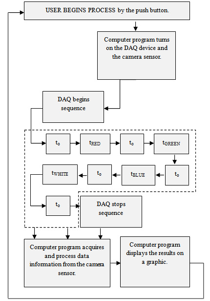
- There were some considerations for the correct design and construction of the optoelectronic device. 1) the pupil must be in total darkness to ensure pupil stability and to know the diameter of the pupil under dark conditions 2) The whole event has to be recorded, this means that the initial diameter has to be recorded and from there, all the variations on the pupil diameter due to the external light that, for this experiment, is coming from 3 light-emitting diodes corresponding to Red (R), Green (G) and Blue (B) colors as it is described above. The light stimulation responses, electronically, to a controlled sequence of pulses coming from a programed software in order to ensure a high precision method. 3) A camera sensor has to be considered into the optoelectronics design. 4) Due to the darkness condition, it will be impossible for the camera sensor to record any pupil change; in this case, a couple of Infrared Light-Emitting Diodes (IR LED) have to be placed in the device. Figure 1 shows the setup used in this work.
 | Figure 1. Experimental set up for measuring the pupil diameter changes along the time |
 | Figure 2. Structure of the optoelectronics device for measuring pupil dynamics |
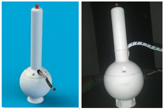 | Figure 3. Optoelectronic device for monitoring pupil changes |
3. Results
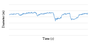
- Figure 4 shows the sequence of pulses of light that are used to stimulate the pupil. These pulses are electronically controlled to turn on and turn off the LEDs. X-axis is in seconds and Y-axis is in meters. The resulted graphic, shown in figure 4, represents the changes on the diameter of the pupil along the time. It is important to mention that the time on darkness, to and the time with light on, tRED, tGREEN, tBLUE, can be configured in the computer program, x – axis is in seconds, y – axis is the diameter of the pupil measuring in meters.As it is shown, the resulted graph contains 4 peaks representing the pupil reaction to external stimulation of light in RGB color model and white light stimulation. This kind of non-contact measurement can help to the study and diagnostic of different diseases on the human body. Because this measurement is a digital one, all the data can be mathematical processed to have a good quality correlation to all the different diseases to be studied for future works. The computer interface, figure 6, shows the results of the pupil changes of diameter and area along the time.
 | Figure 4. Sequence of light pulses electronically controlled to stimulate the pupil |
 | Figure 5. Pupil reaction lo RGB light stimulation |
 | Figure 6. The interface used together with this optoelectronic device shows the pupil and its reaction in real time during the measurements. The couple of graphics shown the reaction of the diameter and the area of the pupil to light stimulation against time |
4. Conclusions
- The proposed optoelectronic device has big advantages; is a non-contact, fast, economic and secure way to study diseases on the human body.The resulted graph gives a very clear idea of how the changes on the pupil diameter along the time and due to external light stimulations can be correlated to neurological reactions. This is a novel idea that can help for opportune diagnostics and to follow particular diseases with the objective to improve the quality of people life.It is important to mention that the pupil reactions are related to different conditions ranging from iris atrophy, eye surgical procedures or any other ocular condition that may affect the performance of the described device making the results highly unpredictable, however, because of the digital measuring coming from this device, this kind of conditions could be considered before the application of the device for a specific study or disease evaluation to generated a proper research method and an adequate processing of the acquired data.
ACKNOWLEDGEMENTS
- The authors wants to acknowledge to the Centro de Biotecnología Óptica Aplicada y Asociados and the Consejo de Ciencia y Tecnología del Estado de Guanajuato (CONCYTEG – Project 168731) for their support in this work.