American Journal of Biomedical Engineering

p-ISSN: 2163-1050    e-ISSN: 2163-1077

2013;  3(6): 119-131

doi:10.5923/j.ajbe.20130306.01

Electrochemical Synthesis, Characterisation, and Preliminary Biological Evaluation of an Anodic Aluminium Oxide Membrane with a pore size of 100 nanometres for a Potential Cell Culture Substrate

Gérrard Eddy Jai Poinern1, Xuan Thi Le1, Marilyn Hager2, Tom Becker3, Derek Fawcett1

1Murdoch Applied Nanotechnology Research Group, Department of Physics, Energy Studies and Nanotechnology, School of Engineering and Energy, Murdoch University, Murdoch, Western Australia 6150, Australia

2Animal Health Laboratories, Animal Virology, Department of Agriculture and Food, 3 Baron Hay Court, Kensington, Western Australia 6150, Australia

3Department of Chemistry, Curtin University of Technology, Bentley, Western Australia 6102, Australia

Correspondence to: Gérrard Eddy Jai Poinern, Murdoch Applied Nanotechnology Research Group, Department of Physics, Energy Studies and Nanotechnology, School of Engineering and Energy, Murdoch University, Murdoch, Western Australia 6150, Australia.

Email:

Copyright © 2012 Scientific & Academic Publishing. All Rights Reserved.

Abstract

In this study we investigate the electrochemical synthesis and characterisation of a nanometre scale porous anodic aluminium oxide (AAO) membranes with a mean pore diameter of 100 nm. The membranes exhibit interesting properties such as controllable pore diameters, periodicity and density distribution. These properties can be preselected by adjusting the controlling parameters of a temperature controlled two-step anodization process. The surface features of the nanometre scale membrane such as pore density, pore diameter and inter-pore distance were quantified using field emission scanning electron microscopy (FESEM) and atomic force microscopy (AFM). A preliminary biological evaluation of the membranes was carried out to determine cell adhesion and morphology using the Cercopithecus aethiops[African green monkey – (Vero)] kidney epithelial cell line. Optical microscopy, FESEM and AFM investigations revealed the presence of focal adhesion sites over the surface of the porous membranes. The positive outcomes of the study, indicates that AAO membranes can be used as a viable tissue scaffold for potential tissue engineering applications in the future.

Keywords: Regenerative Tissues, Nano-porous Anodic Aluminium Oxide, Cell Substrate, Tissue Scaffold

Cite this paper: Gérrard Eddy Jai Poinern, Xuan Thi Le, Marilyn Hager, Tom Becker, Derek Fawcett, Electrochemical Synthesis, Characterisation, and Preliminary Biological Evaluation of an Anodic Aluminium Oxide Membrane with a pore size of 100 nanometres for a Potential Cell Culture Substrate, American Journal of Biomedical Engineering, Vol. 3 No. 6, 2013, pp. 119-131. doi: 10.5923/j.ajbe.20130306.01.

1. Introduction

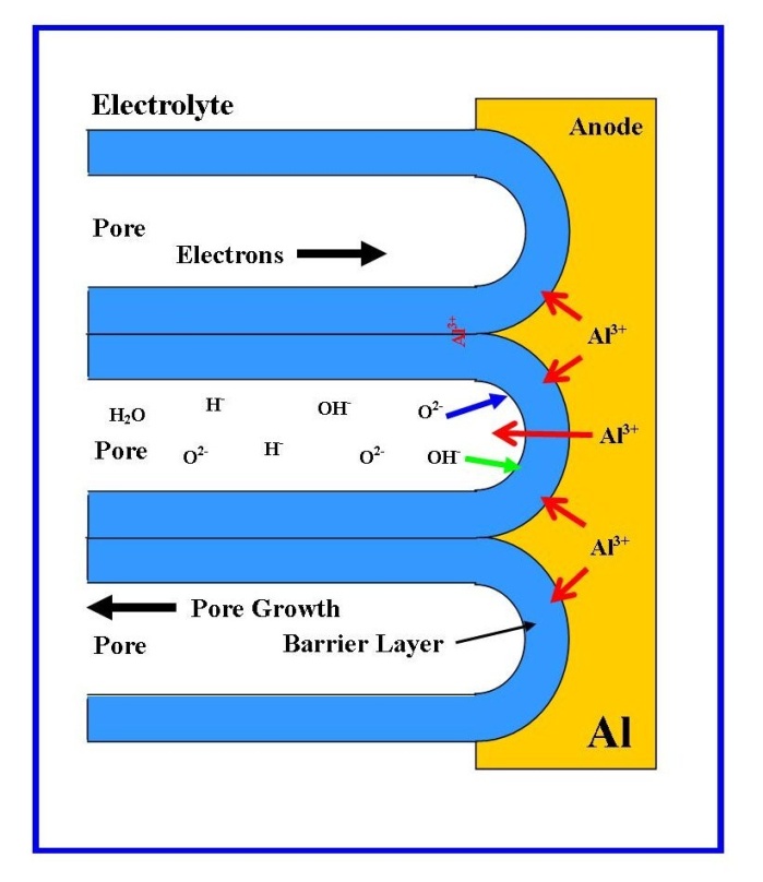
The primary function of tissue engineering is to create an environment that can promote productive biological processes and cellular signals, which can create or repair damaged tissues by rational design[1]. However, this environment is influenced by four main factors: 1) the types of cells; 2) the structure and physiochemical properties of the scaffold; 3) the biological processes, and 4) cellular and scaffold signals[2]. Individual cells are generally in the micron-size range, but their component structures and surrounding environment are in the nanometre to micrometre scale range. Cells actively interact with the surrounding topography and the molecular building blocks of life such as proteins, which are crucial for controlling cell functions such as proliferation, migration, and the production of the extracellular matrix, (ECM)[3].
Furthermore, the chemical and physical structure of the topography directly influences the behaviour of the cell in contact with the surface. For example, the adhesive attachment of a cell to a substrate surface is via protein adsorption, which is highly dependent on surface properties such as surface charge, surface chemistry[4], wettability[5], surface density of cell-binding ligands[6] and nanometre scale topography[7]. Therefore, to achieve a successful clinical outcome it is crucial that a tissue scaffold be completely biocompatible, i.e. no cytotoxicity, immunological reactions and inflammatory responses from the surrounding tissues[8-10]. The surface chemistry and wettability of the tissue scaffold are also important factors, since they must be chemically compatible with both the ECM and cellular tissue. By mimicking the ECM, the tissue scaffold promotes an environment, which actively supports the creation of new ECM, cell adhesion, intercellular interaction, proliferation and migration[11]. While the wettability of materials used to construct a tissue scaffold must also be carefully considered, since hydrophobic materials will not promote successful cell adhesion and attachment. It is also extremely important at the cell level, that the tissue scaffold also contains a network of pores and interconnecting channels to facilitate the diffusion of nutrients, oxygen, metabolites and waste products. Both pore size and pore surface area to volume ratio have been found to be important parameters in encouraging the in-growth of cells into the matrix of the tissue scaffold forming cellular associations[12].
The earliest clinical use of an aluminium oxide (Alumina) ceramic as a biomaterial has its origins in the 1970’s, when Hamadouche et al. successfully used it in a total hip arthroplasty procedure[13]. However, the study of porous aluminium oxide membranes derived from the anodization of aluminium metal made in a variety of polyprotic acids or electrolytes, temperatures and Anodization voltages goes back more than sixty years[14]. During anodization in a polyprotic acid (e.g., oxalic, phosphoric or sulphuric acid), the electrochemical process produces a nanometre scale porous oxide layer over the metal surface. A typical schematic of an experimental setup is presented in Figure 1. The first systematic study of this porous oxide layer was carried out by Keller and co-workers in 1953. This study revealed that the structure of the pore formed during anodization was the result of the solvent action of different electrolytes on the oxide coating and the dependence of anodic voltage on pore size[15].
The anodization process begins with Al3+ ions migrating from the Al metal across the metal/oxide interface into the forming surface oxide layer[16]. Meanwhile at the oxide/electrolyte interface, O2- ions formed in the electrolyte migrate into the oxide layer. The forming oxide layer (or barrier layer) consumes 70% of the available Al3+ ions, while the remaining Al3+ ions are dissolved into the electrolyte[17]. This balanced flow of Al3+ ions is a prerequisite for porous oxide growth and also takes into account the Al-O bonds in the oxide lattice breaking to release Al3+ ions[18]. The steady state growth in the pore structure results from the balance between the field-enhanced oxide dissolution at the oxide/electrolyte interface and the oxide growth at the metal/oxide interface. The electric field is high enough in the hemispherical shaped pore bases to propel the Al3+ ions through the barrier layer (the electric field strength in the pore walls is too small to make any significant contribution to the flow of ions), while the migration of O2- and OH- ions into the pore base oxide maintains the layers constant thickness[14, 19, 20]. The oxidation takes place over the entire pore base, with pronounced perpendicular oxide growth occurring at the pore boundaries, see Figure 2. In addition, the presence of neighbouring pore growth prevents oxide growth in any other direction and also explains the dependence of pore diameter to the strength of the electric field produced by the anodizing voltage. The net result of the oxide growth is a porous structure that contains numerous columnar structures, with a high aspect ratio and each containing a central circular channel, which extends from the base of the pore to the surface of the oxide layer.
Figure 1. Schematic of a typical experimental setup for anodization of aluminium
Figure 2. Schematic of pore formation mechanism in an acidic electrolyte
Unfortunately, the anodization process generally produces a disordered arrangement of pores. However, in 1998, Masuda et al. using a two-step anodization process were able to produce a highly ordered hexagonal pore structure from a set of pre-arranged macroscopic parameters such as acid type and concentration, temperature and anodization voltage[21]. Thus, by controlling the macroscopic parameters it was possible to dictate the resulting nanometre scale structures formed in the resulting anodic aluminium oxide (AAO) layer. For example, the size of the pore diameter was found to be dependent on the electrolyte and anodizing voltage, while a large aspect ratio pore structure or membrane thickness was found to depend on the duration of the anodization process[19, 22]. These attractive features have made porous AAO membranes an ideal template for a variety of nanotechnology based applications such as the synthesis of nanometre scale materials and devices[23-25], as biological/chemical sensors/electronic devices[26-29], filter membranes[30] and potential medical scaffolds for tissue engineering applications[31-33].
The present study is composed of three parts. The first two parts deal with the synthesis and characterization of the porous AAO membranes and forms the main thrust of the study, before a preliminary biological evaluation of the membranes is carried out. The first part consists of synthesising porous AAO membranes via the anodization of aluminium metal. An optimized two-step anodization process was used to produce a highly ordered hexagonal pore structure with a mean pore diameter of 100 nm from a set of refined pre-arranged macroscopic parameters. The mean pore diameter of 100 nm was selected for two reasons: 1) previous studies had indicated that this pore size had the potential to induce a favourable cellular response[34]; and 2) a commercially available 0.1 µm pore diameter (100 nm) Whatman® Anopore (Anodisc) membrane could be used throughout the study for comparative purposes. In the second part of the study a detailed FESEM examination of both the in-house synthesised AAO membranes and the commercially available Whatman® Anopore (Anodisc) membranes was carried out to investigate major surface features such as pore density, pore diameter and inter-pore distance. In addition to the FESEM examination an AFM analysis of the membrane surface was also carried out to confirm the presence of features and highlight the surface topography. Statistical analysis was then used to quantify the dimensions of the nanometre scale porous oxide structure of both types of membrane investigated. The third part of the study involved a preliminary biological evaluation of the porous membranes by examining both cell adhesion and morphology of the Cercopithecus aethiops[African green monkey – (Vero)] kidney epithelial cell line. Cell adhesion and morphology on all membranes and a glass control were investigated using optical microscopy, FESEM and AFM.

2. Materials and Methods

2.1. Materials

All chemicals were purchased from Sigma-Aldrich (Castle Hill: NSW, Australia) and used without further purification. Milli-Q® water (18.3 MΩ cm-1) was used in all aqueous solution preparations and was produced from a Barnstead Ultrapure Water System D11931 (Thermo Scientific, Dubuque, IA). The 99.99% pure aluminium foil (0.25 mm thick) was supplied by Alfa Aesar (USA) and the Anodisc membrane (diameter 25 mm, pore size 0.1 µm) used for comparative purposes was supplied by Whatman® Anopore (UK).

2.2. Fabrication of in-house Nano-porous AAO Membranes

Fabrication of the in-house membranes begins with a 100 mm square Aluminium (Al) high purity (99.99%) sheet, 0.25 mm thick supplied by Alfa Aesar, USA being cut into 50 mm x 20 mm strips. The strips are then placed into a tube furnace and annealed in a nitrogen atmosphere at 500 °C for 5 hours to initiate re-crystallisation and release mechanical stresses in the strips. After annealing, the strips were degreased in acetone and then etched in a 3.0 M sodium hydroxide solution for 5 minutes before being thoroughly washed in Milli-Q® water. The strips were then dried before a thin layer of polymer was applied to one side of the strip. Once the polymer had set, the strip was ready for the first step of the two-step anodization procedure. During the first step, each strip was anodized using a voltage of 60 V in an electrolyte solution consisting of 0.3 M oxalic acid for 5 hours. At the end of the first anodization step: the resulting thin oxide layer formed on the non polymer coated side of the strip was removed from the substrate by immersion in a stirred acidic solution composed of phosphoric and chromic acid (70 mL/L and 20 g/L, respectively) at 60 °C for 1 hour. This is an important stage of the process, since it selectively removes the first oxide layer and exposes a highly periodic and indented landscape covering the surface of the Al substrate. These indentations will form the initiation sites for pores formed in the second anodization step. The second anodization step is performed under the same conditions as the first step, except that the period of anodization is only for 3 hours. During the second step, a regular, honeycomb array of nanometre-sized pores are formed across the surface of the oxide layer. After the second anodization, the pores were then widened by chemical etching in a 5% solution of phosphoric acid at 35°C for 15 minutes. Then a thin layer of Acrifix® 192 polymer was applied to the anodized side of the Al strip. This serves as a physical support for the membrane during the removal of the Al substrate using an acidic solution mixture composed of 0.1 M copper chloride and 7% hydrochloric acid. Following the removal of the Al substrate, the barrier layer was removed from the membrane by etching in a 0.3 M solution of phosphoric acid. The final etching stage, results in the complete dissolution of the barrier layer and the acrylic support leaving an off white coloured oxide membrane. The final stage in producing the membrane is sterilization, which involved immersing the membranes in a 30% solution of hydrogen peroxide at 60ºC for 15 minutes. This was followed by quickly dipping the membrane into a solution of Milli-Q® water for 10 seconds to remove any hydrogen peroxide from the membrane surface and then placed under ultraviolet light for 2 h. The membranes are then placed in airtight containers, wrapped in Al foil and stored for future use. Figure 1 presents a field emission scanning electron microscopy micrograph of a typical AAO membrane fabricated in-house using the two-step anodization procedure.

2.3. Characterization of Substrates and Cells

The in-house fabricated nano-porous AAO membranes and Whatmann® Anodisc membranes were examined using a field emission scanning electron microscopy (FESEM). The micrographs were taken using the Zeiss Neon 40EsB FIBSEM (Carl Zeiss, Oberkochen, Germany) located at the Centre for Materials Research (CMR) at Curtin University of Technology. The field emission electron gun provided both high brightness and high resolution (0.8 nm). Samples were mounted on individual substrate holders using carbon adhesive tape before being sputter coated with a 2 nm layer of platinum to prevent charge build up using a Cressington 208HR High Resolution Sputter coater. Micrographs were taken at various magnifications ranging from 2 to 5 kV using the SE2 and In-Lens detectors. The AFM images were taken using the Digital Instruments Dimension 3100 AFM set for Tapping Mode. The AFM tips used were supplied by Nano-world innovative technologies and the silicon SPM sensor (non contact mode) was supplied by NCH-W Point-Probe[Thickness 4 µm, Width 30 µm and Length 125 µm]. The AFM’s force constant was 42 N/m and its resonance frequency was 320 kHz. Optical microscopy (OM) was used throughout the cell studies to examine cell-membrane interactions such as attachment, migration and proliferation. An Olympus BX51 compound microscope (Olympus Optical Co. Ltd., Tokyo, Japan) was used for all optical studies and photographs were taken using the DP 70 camera attachment.
Before optical microscopy observations, cells adhering to each respective membrane were fixed using a 1:1 solution of acetone and methanol. The cells were then stained using an aqueous solution containing 1% Fuchsin acid. After 1 h the excess stain was rinsed off the membranes using Milli-Q® water. After the membranes had dried, they were then mounted onto microscope slides ready for optical microscopy investigation at various magnifications (4x, 10x, 20x and 40x). Before FESEM observation could be carried out, the cell/membrane samples needed to be washed in increasing concentrations of ethanol prior to being sputter coated. Initially the cell/membranes were washed in a 30% solution of ethanol several times before being allowed to soak for 15 minutes in the ethanol solution. At the end of this period, sequential drying of the samples using progressively increasing concentrations of ethanol washes (2 washes of 50%, 70%, 80%, 90%, and 95%) was carried out until finally being washed in a solution of 100% ethanol for 30 minutes. Following the ethanol washing procedure, the samples were then treated with a 50:50 solution of ethanol:amylacetate for 30 minutes. This was then followed by 2 immersions in amyl acetate over a period of 1 h before being placed into a critical point dryer. Finally, the dried cell/membrane samples were mounted on FESEM stubs before being sputter-coated with a 2 nm layer of platinum metal for imaging purposes. The samples were then ready for FESEM investigations.

2.4. Cell Culturing and Growth on Membranes

2.4.1. Cell Seeding and Culture
The cell line used in this in vitro study was the Cercopithecus aethiops (African green monkey) Kidney (Vero) epithelial, and were supplied by the Animal Health Laboratories, Animal Virology, Department of Agriculture and Food, 3 Baron Hay Court, Kensington, Western Australia 6151, Australia. The cell culturing protocol was carried out in accordance with the Animal Health Laboratories procedure VIW-17 using a Cell Growth Medium 199 (Sigma-Aldrich) and 10 % fetal calf serum (FCS)[35]. A standard cell culturing procedure used in previous AAO cell line studies by the authors is presented and discussed in reference[34].
2.4.2. Cell Adhesion and Morphology Studies
Both types of nano-porous membranes (in-house and Whatmann® Anodisc) were used without surface treatments, other than sterilization along with the glass controls prior to cell seeding. The cell adhesion studies started with making up a series of sample sets. Each sample set consisted of adding 2 samples of each nano-membrane type and 2 glass controls to a 6 well culture plate (No 657-160) supplied by CellStar® Greiner Bio-One, Germany. Then a 3 mL solution of Vero cells (approximately 3x10⁵ cells/mL) suspended in culture medium and 10% FCS were transferred to each well of the culture plate using a pipette. The well plates were then gently oscillated to disperse the cells and then incubated at 37˚C under a 5 % CO2 atmosphere. After 24 h the well culture plate was removed from the incubator and the individual membranes and glass controls were washed and then fixed using a 1:1 solution of methanol: acetone. After 10 minutes, the membranes and glass controls were removed from the fixing solution and allowed to air dry at room temperature. Then the cells on both membranes and glass controls were stained using an aqueous solution containing 1% Fuchsin acid. After soaking the samples for 1 h, the excess stain was rinsed off Milli-Q® water and allowed to air dry at room temperature. After the samples had dried, each sample was mounted onto microscope slide before a cover slip was added. The samples were then ready for optical microscopic investigation. The cell adhesion procedure was carried out in triplicate to ensure consistency in the study.

2.5. Statistical Analysis

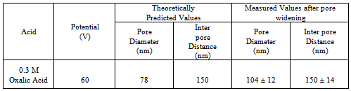
The frequency and size of the particular surface features such as pore diameter, pore density and inter-pore distance was determined by counting and physically measuring the size of the features found within 10 randomly selected 1 µm square grids. From this analysis the mean ± standard deviation of each surface feature was calculated.

3. Results and Discussions

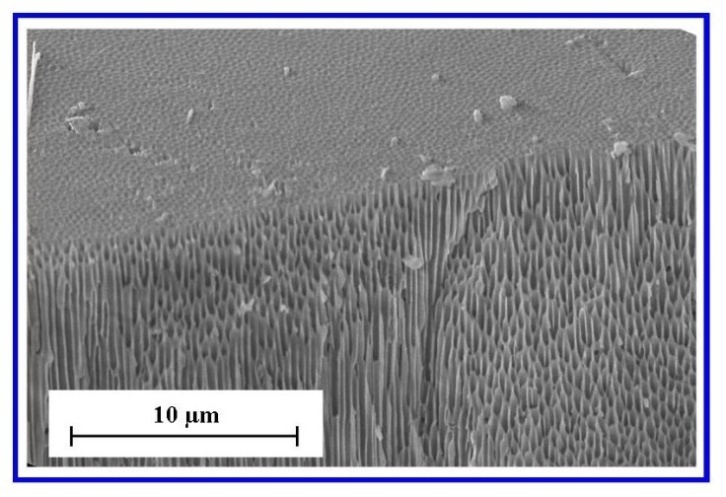
FESEM characterisation of the surface terrain of the in-house AAO membranes produced by the two-step anodization procedure revealed an architecture that was highly ordered, with close packed hexagonal arrays of uniformly sized pores. The ordered pore domains are tessellated across the undulating landscape of the membrane surface as shown in Figure 3(a).
Examination of the FESEM micrographs revealed that between the pore domains were occasional non-ordered pores resulting from point defects, dislocations and grain boundaries in the Al substrate and have also been reported by other researchers[36, 37]. In addition, the FESEM micrographs also revealed the presence of a smaller number of minor pores merging with larger, nearby neighbouring pores to form elliptical shaped pores. The bottom of the membrane, which was etched to remove the barrier layer and open up the pores, had a similar surface topography to the upper surface. The second step of the two-step anodization process, which lasted 3 hours’ produced a highly porous and permeable membrane composed of highly linear channels that traverse the membrane, see Figure 3(b).
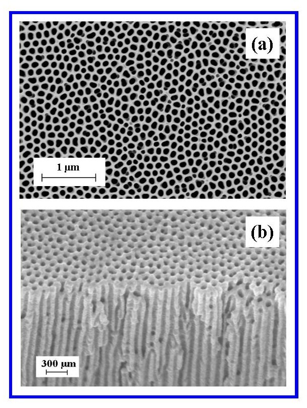
Figure 3. (a) A typical FESEM image of an AAO top view, surface landscape showing ordered pore domains; (b) A typical image of nano-channels traversing the AAO membrane
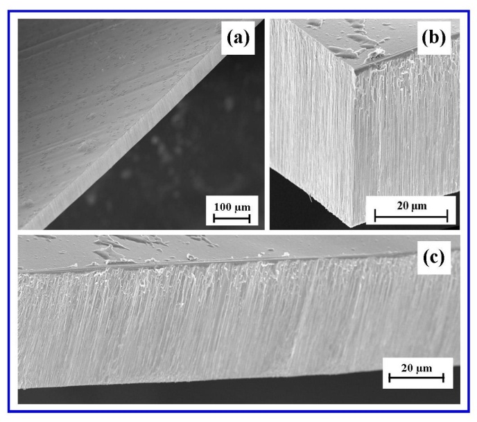
Figure 4. a) A typical AAO membrane used in the polymer dipping procedure; (b) Edge view of a typical AAO membrane showing vertical growth pattern and (c) Side view of AAO membrane showing vertical growth pattern of oxide layer
The 3 hour second anodization step produced an oxidation layer that was highly reproducible and consistent across the whole Al substrate. After the porous oxide layer was removed from the substrate, the barrier layer was then removed. This produced a porous oxide layer that exhibited the same consistent thickness across the whole membrane as shown in Figure 4(a). Figures 4(b) and 4(c) present two views of the vertical growth pattern found in the oxide layer which forms the membranes porous structure. The thickness measurements, based on FESEM images revealed that the membranes had a fairly consistent thickness of around 40 µm, see Figures 4(c) and 6. In comparison the commercially available Whatman® Anodisc membrane thickness was typically around 60 µm in thickness. Furthermore, inspection of the in-house AAO membrane found that it tended to be an off white colour, hard and brittle, with very little flexibility. Other structural features found in the in-house AAO membranes and the Whatman® Anodisc membranes are discussed in the following discussions.
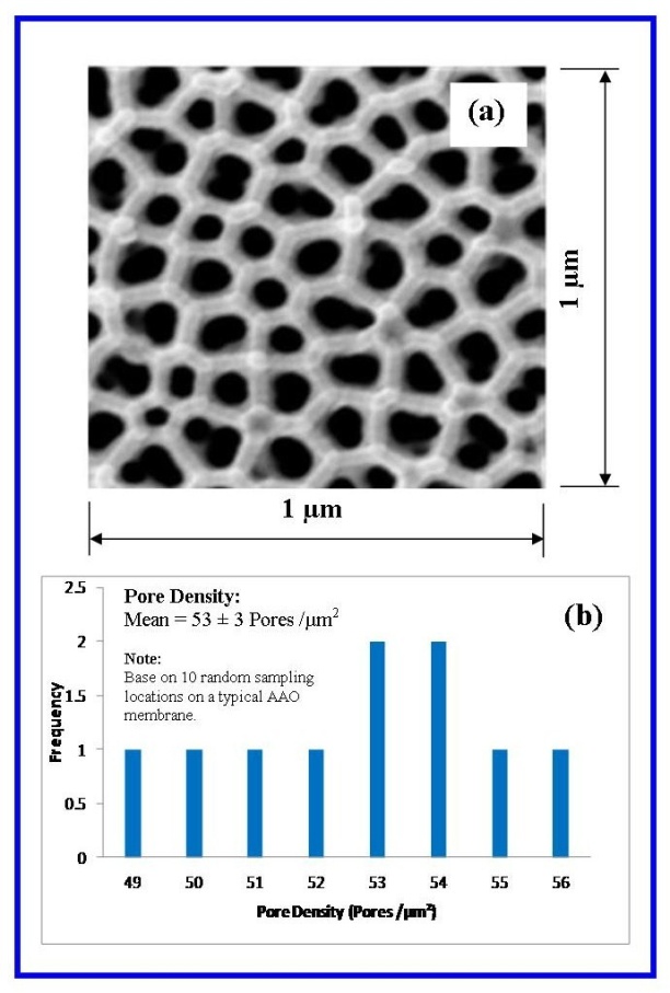
Figure 5. (a) A representative counting square used for determining pore density; (b) Statistical analysis of pore numbers counted in 10 random locations on a typical AAO membrane[34]
The mean pore density of the synthesised AAO membranes was determined from an FESEM survey of the membranes landscape. Several 1 µm2 locations were randomly selected from various locations across the membrane, and then the number of pores found within the1 µm2 was counted. A typical 1 µm2 location used in the pore density survey is presented in Figure 5(a) and a typical histogram of the statistical analysis is presented in Figure 5(b). The pore density survey and subsequent statistical analysis revealed that the pore density was 53 ± 3 pores/µm2 (mean ± std), with a pore diameter of 104 ± 12 nm and an inter-pore distance of 150 ± 14 nm as shown schematically in Figure 6.
Inspection of the histogram presented in Figure 5(b) indicates a small variation in pore densities found across the membrane. Similar narrow size distributions can be seen for both the pore diameter and inter-pore distance as shown in Figures 6(a) and (c) respectively. In addition, analysis also revealed that there was also a narrow size distribution in the pore wall thickness histogram as shown in Figure 6(b). The analysis gave a value of 22.3 ± 3.1 nm for the mean pore wall thickness. The narrow size distribution in these nanometre scale features is a clear demonstration of the two-step anodization techniques ability to consistently produce a highly regular, closely packed and uniform array of pores. This consistency was extremely important since the subsequent in vitro cell studies had to be carried out on membranes with a consistent and well-defined surface topography. This reproducibility enabled multiple cell experiments to be carried out to determine the effect of nanometre scale topography promoting cell attachment.
A significant feature of the in-house AAO membrane in cross-section is the striking linearity of the pore channels that transverse the porous structure. Examples of this feature can be seen in Figures 3(b) and 7. To investigate this feature further, a membrane was cleaved, prepared for FESEM and imaged. The results of the FESEM examination are presented in Figure 6 and reveal the intricate nanometre scale channel formations found within the porous structure of the membrane. Figure 7(a) is a typical view of the cleaved plane and highlights the highly ordered and closely packed array of nanometre scale channels found in the membrane. The blue square on the left of Figure 7(a) is enlarged in Figure 7(b); this enlargement highlights a group of nano-channels that have been sheared by the cleaving process. The red arrows indicate channel openings which are clearly aligned the within the structure. The vertical orientation is also evident in the blue parallelogram, which is enlarged in Figure 7(c). Figure 7(d) presents a schematic representation of the cleaved plane that has resulted in fracturing across the channels to produce a series of vertical lines.
From the FESEM micrographs, the distance measured between 8 vertical curves shown in Figure 7(c) and schematically presented in Figure 7(d) was found to be 950 nm, while the calculated distance based on circular pore geometry (104 nm mean diameter and 22.5 nm mean wall thickness) gave a value of 975 nm. Measurements of the vertical alignment of the channels clearly indicated that the channels were parallel and no bifurcations or other defects were seen in the membrane cross-sections examined. However, it is expected that theses imperfections do exist because there is evidence of a smaller number of pores merging with larger neighbouring pores to form elliptical shaped pores. This merging of smaller pores with larger pores generally occurs at the domain boundaries and is also expected to produce imperfectly formed channels. Nanometre scale channel formation was also present in the commercially available Whatman® Anodisc membranes. These membranes were used for comparative purposes in this study. Figure 8 presents an FESEM image of a cleaved cross-sectional view of a typical Anodisc membrane. The vertically aligned nanometre scale channels are clearly visible in the porous membrane structure.
O’Sullivan and Wood established linear relationships between two membrane parameters, namely the size of the pore diameter and the distance between neighbouring pores[19]. Both parameters were found to be independent of electrolyte used and both were found to be highly dependent on the applied anodization potential. The results of their studies enabled them to theoretically model the size of the pore diameter and the distance between neighbouring pores. The size of the pore diameter was predicted to increase at a rate of 1.29 nm V-1, while the distance between neighbouring pores was expected to increase at a rate of 2.5 nm V-1. Using these two parameter predictions, it was possible to compare the calculated theoretical values with those of experimentally measured values. The experimental values of pore diameter and inter-pore distance determined in this study are compared to the theoretical predictions of O’Sullivan and Wood Table 1.
Table 1. Comparison of theoretical and measured values for pore diameter and pore spacing of the in-house AAO membrane
     
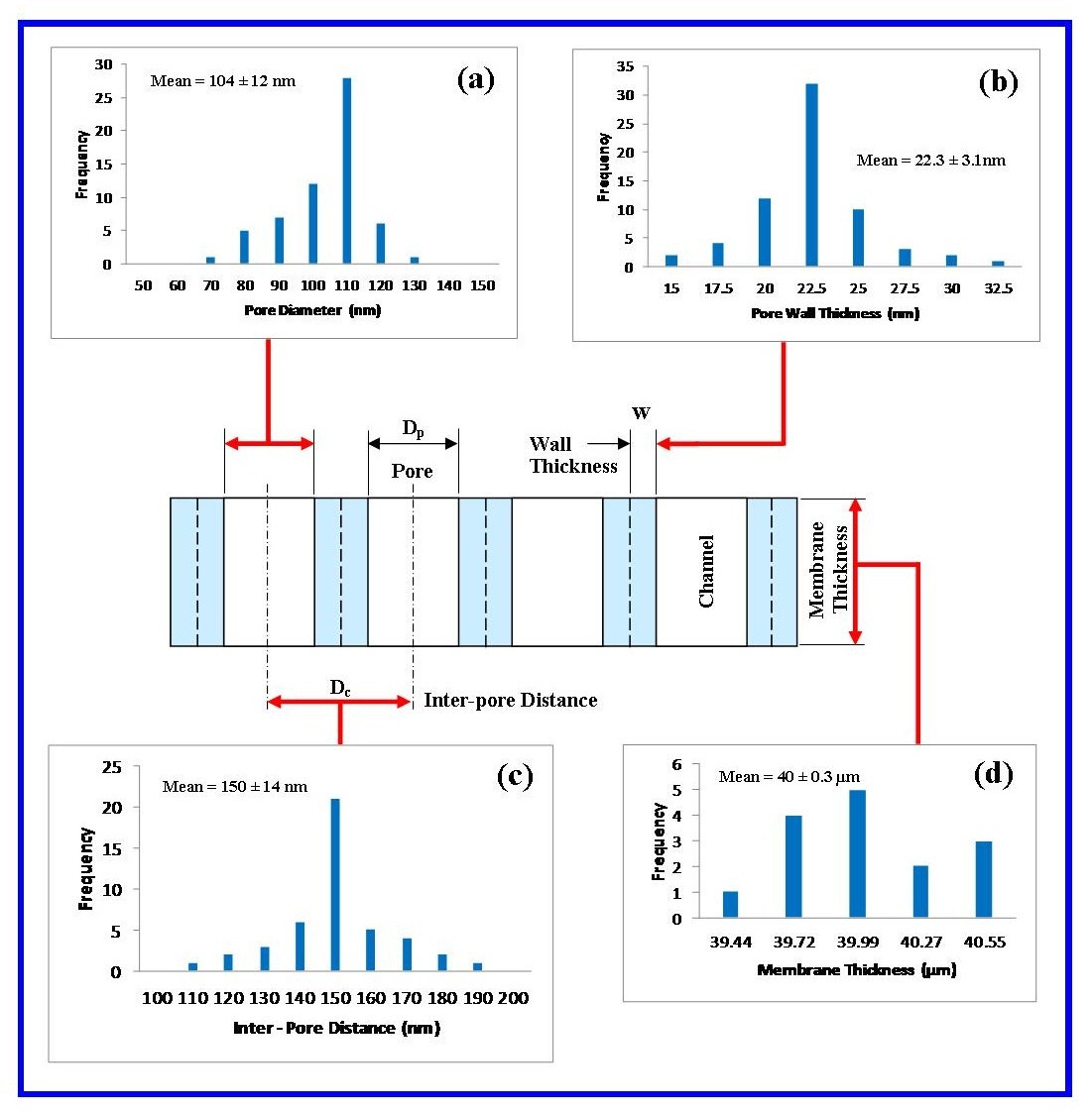
Figure 6. Results of the investigation into nano-scale features found in AAO membranes: (a) Pore diameter analysis; (b) Pore wall thickness; (c) Inter-pore distance and (d) Membrane thickness
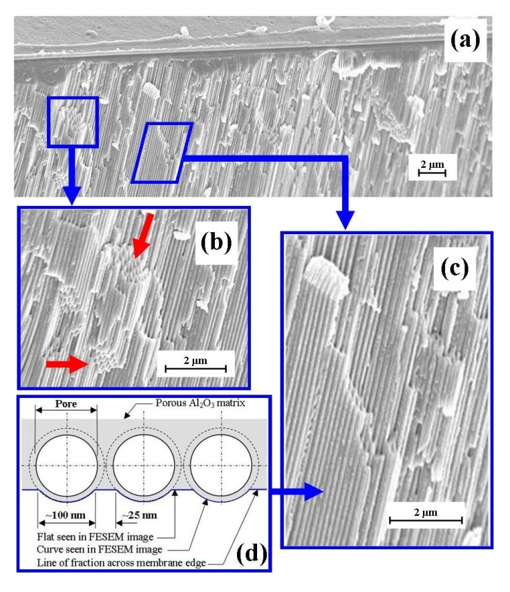
Figure 7. Structural features and orientations of the nano-channels formed in the AAO membrane (a) cleaved membrane; (b) enlargement of nano-channel openings; (c) vertical orientation and linearity of nano-channels, and (d) schematic of the fracturing occurring across the nano-channels
Figure 8. Cross-sectional view of angularly cleaved Anodisc membrane showing nano-channels and channel openings
Inspection of Table 1 reveals the value of the pore diameter obtained in this study is larger than the theoretically predicted value. The difference in pore size was expected, since the two-step anodization process using the operational parameters produces pore sizes in the range from 70 nm to 90 nm. The enlarged pore diameters were the result of subsequent pore opening and widening procedures carried out after anodization. During both pore opening and widening, the membrane is subjected to immersion in an acidic media for 15 minutes. This is followed by the membrane receiving a final etching in an acidic solution for 10 minutes to clean and define the pores. As expected, the theoretical inter-pore distance was comparable to the measured value, since subsequent pore opening and widening procedures did not affect this geometric parameter.
Another feature of the pore stuttered landscape of the in-house AAO membrane was the presence of a small number of elliptical shaped pores as seen in Figures 3(a) and 5(a). The elliptical shape is believed to be the result of Joule heating produced by the chemical dissolution rate of the oxide layer and fluctuations in the anodization current and voltage.
The fluctuating current and voltage results from heat induced stresses at the metal/oxide interface and within the barrier layer which produces changes in the impedance of the forming oxide[22]. Another contributing factor to the fluctuating current and voltage is the initial morphological changes of the barrier layer from the initial landscape of hemispherical depressions to the enhanced accumulation of oxide at the rims of the hemispheres forming the foundations of the pore walls[38].
Although significant progress has been made in the manufacture of AAO membranes for a number of template related nanotechnology based applications, there are still many features of the pore self-organisation mechanism that still remain largely unresolved. Many researchers have proposed a number of mechanisms to explain the formation of the highly ordered structure and closely packed hexagonal arrays of uniformly sized pores. The mechanisms reported to date include mechanical stress-guided repulsion [39], electric-field dependent interface evolution[19] and viscous oxide flows from the barrier layer to the pore walls[40, 41]. Whether the induced interfacial stresses resulting from volumetric expansion of the forming oxide layer induces pore self-organisation, or the field assisted plasticity of the oxide layer which permits the viscous flow of oxide in the vicinity of the pore bases. The kinetics and mechanisms behind pore formation currently don’t provide any detailed information regarding the exact nature of self-organisation during pore domain formation. The most likely explanation could be that self-organisation occurs through the growth of pore domains possessing a superior in-plane orientation that gradually results in other in-plane orientations disappearing in a similar way to Ostwald ripening.
Several studies have discovered that the degree of long range ordering of pore domains is highly dependent on the anodization period, with the mean pore domain area linearly increasing with the Anodization time[22, 36, 42-44]. Ideally, long anodization periods have the potential to produce a higher degree of long range pore domain ordering. Masuda and Fukuda have reported the formation of near perfect pore domains for anodization periods approaching 160 h[21]. However, the in-house AAO membranes produced in this study did not have the idealistic pore domains reported by Masuda and Fukuda. Instead, the two-step anodization procedure was optimised to produce an ordered structure, with domains containing uniformly sized pores within a reasonable and practical time frame. The optimised processing times of both anodization steps was able to produce membranes with a high degree of pore ordering and well defined consistent nanometre scale topography over the entire membrane surface as illustrated in Figure 3(a) and 6. In addition, the use of high purity (99.99%) Al foil, pre-annealed prior to anodization also contributed to the reduced number of foreign contaminant elements occupying lattice points within the Al foil. The presence of both lattice point contaminants and randomly distributed point defects in the Al lattice have the potential during anodization to disrupt or destroy the close-packed order of the developing pores[37]. Membranes synthesised in this study had relatively few surface defects and the resulting nanometre scale topography was found to be acceptable for the cell attachment studies.
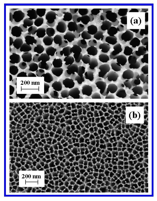
Figure 9. FESEM images of commercially available Whatman® Anopore (Anodisc) membrane (0.1 µm pore diameter), (a) Top surface and (b) Bottom surface
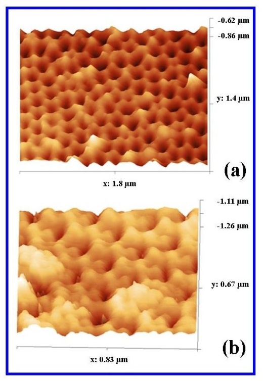
Figure 10. AFM surface analysis of (a) in-house AAO membrane and (b) Whatman® Anopore (Anodisc)
The comparative membrane used throughout the study was the commercially available Whatman® Anopore (Anodisc) membrane. The membranes nanometre scale porous structure makes it ideally suited to a wide variety of laboratory based filtration applications[45]. The membranes are supplied in 3 nominal pore sizes: 0.02 µm, 0.1 µm and 0.2 µm, with a nominal membrane thickness of 60 µm. Studies by Fisch et al. using X-ray diffraction spectra for 0.1 and 0.2 µm pore sizes found a mean inter-pore distance of around 0.37 µm[46]. In this study, pore geometry and distribution was found to be consistent across the membranes (no pore domains present). The mean pore diameter was calculated to be 120 ± 45 nm and the inter-pore distance ranged from 0.32µm to 0.37 µm. However, pore wall thickness was not consistent across the membrane and the presence of rough edges protruding up from the surface between the pores was a characteristic of the Anodisc membrane as seen in Figure 9(a). Taken as a whole, the surface of the Anodisc membranes was very rough compared to the in-house fabricated AAO membranes, which were much smoother and undulating. Another feature of the Anodisc membranes was that they tended to have a less refined nanometre scale topography compared to the in-house AAO membranes. The greater surface roughness and less refined nanometre scale topography found on the Anodisc membrane was further quantified using AFM analysis. The AFM analysis confirmed the much rougher surface landscape of the Anodisc membrane and the smoother, more refined nanometre scale topography of the in-house AAO membrane as seen in Figure 10.
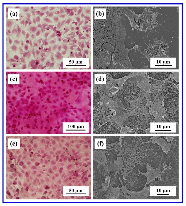
Figure 11. Microscopy of Vero cells at the 24 h period (a) & (b) glass substrate control, (c) and (d) Whatman® Anodisc (c) & (f) in-house AAO membrane Optical microscopy (a), (c) & (e); FESEM (b), (d) & (f)
The preliminary biological evaluation of both AAO membranes and the glass control consisted of cultivating Vero cells on each substrate for 24 h and then examine the degree of cell attachment on each substrate. From the cellular perspective, cell attachment is the interaction between the cell and the surface topographical features of the substrate surface. It is the physical structure and chemistry of the micrometre and nanometre scale features that directly influences the behaviour of the cell in contact with the surface. In addition, the adsorption of proteins onto the substrate surface results in the formation of a surface-bound protein layer, which mediates between the surface and the cell surface receptors during subsequent cell attachment. Hence, successful cell attachment is critical and subsequently influences a variety of cell functions such as proliferation, migration, and the production of the ECM[47].
Optical microscopy examination of the Vero cells after 24 h of cultivation on all three substrates as presented in Figures 11(a), (c) and (d), reveal good cell adhesion and wide spread surface coverage. Subsequent FESEM examination as presented in Figures 11(b), (d) and (f) confirmed that the cells cultured on the nano-porous membranes were comparable to those cultured on the glass control substrate. Further FESEM studies revealed the presence of filopodia at the cell boundaries, which tended to spread out over the surface of the substrates. In the case of the nano-porous membranes the filopodia could be seen attaching to the pore structures and then using these attachments as anchorage points. Even though the glass substrate didn’t have the nanometre scale topographical features of the two nano-porous membrane types, cell attachment was made via a layer of protein and ECM which can easily be seen in FESEM micrographs. For example, Figure 12(a) shows the presence of a Vero cell attached to the ECM surface covering on the glass control substrate. In the micrograph the cell filopodia are identified by yellow arrows and clearly show the spreading and interaction of the filopodia with the ECM. Figure 12(b) shows a typical Vero cell attachment to the Anodisc membrane. Cell filopodia are indentified by blue arrows and can be seen spreading outwards from the cell. But unlike the glass control substrate there is significantly less ECM present on the membrane surface. The reduced amount of ECM is also seen for the in-house AAO membrane and in both cases the underlining pore stuttered landscape can be seen. Cell filopodia identified by red arrows in Figure 12(c) also reveal the interaction of the cell with the in-house AAO membrane. The lower amounts of ECM present on the two nano-porous membranes suggest that the Vero cells consider the underlining surfaces are mimicking some of the properties of the ECM that promote cell attachment.
In addition to the FESEM study, cell attachment and cell interaction with the underlining nanometre scale surface topography was also confirmed by AFM analysis. Figure 13 presents a typical AFM image of Vero cells attached to the in-house AAO membrane. The image reveals major filopodia extending across the surface and anchoring the cells to the membrane surface. The AFM analysis confirms that the cells are actively interacting with the nanometre scale topographical features and utilizing the features such as pores as anchoring points. The cells remain firmly anchored to the membrane surface during repeated AFM scans.
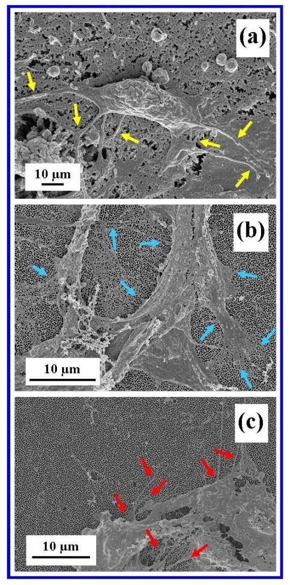
Figure 12. Cell filopodia attaching cell to substrate surfaces (a) Glass control, (b) Whatman® Anodisc and (c) in-house AAO membrane. (Arrows indicate major filopodia)
This study confirms that it is possible to culture Vero epithelial cells that retain histological characteristics on both types of nano-porous membranes. Examination of the optical microscopy images presented in Figure 10 taken after 24 hours of cultivation revealed that the bulk of all three substrate surfaces were covered with cells. The results of the adhesion studies have successfully demonstrated cellular interaction and attachment on both nano-porous membranes and the glass control. However, this study has not provided any biological information regarding the long-term survivability of the Vero cells on the nano-porous membranes. This is currently being addressed by a cell proliferation study, which is expected to provide some insight into the long-term viability of the cells on the nano-porous membranes. The results of this study will be presented in a future publication.
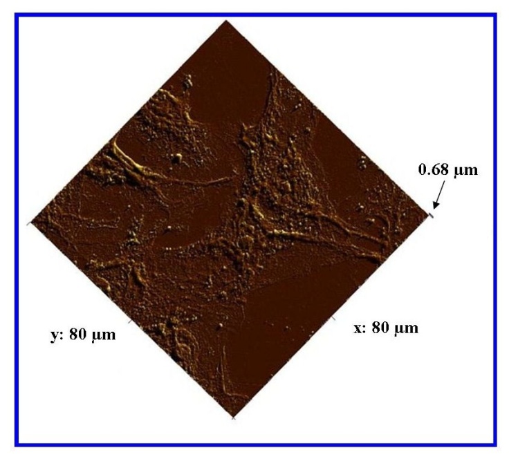
Figure 13. AFM analysis of the in-house AAO membrane showing Vero cells and major filopodia anchoring the cells to the membrane surface

4. Conclusions

The present study has successfully demonstrated that an in-house nano-porous AAO membrane and a commercial AAO membrane have the biological potential for attracting, interacting and promoting cell attachment. The two-step anodization process used to synthesize the in-house AAO membranes was able to produce highly reproducible nanometre scale features by adjusting the controlling experimental parameters. The membranes were used without any further surface modification and showed no cytotoxic effects during the attachment studies. Both AFM analysis and FESEM microscopy provided images that confirmed cell attachment to both nano-porous membrane types. Images revealed the presence of thin filopodia emanating from the cells, spreading across the membrane surfaces and attaching to the nanometre scale topographical surface features of the membranes. Further studies are needed to confirm the long-term survivability of Vero cells on both membranes types. Also the influence of surface texturing on cell attachment and proliferation needs to be quantified before establishing nano-porous AAO membranes as a viable tissue scaffold.

ACKNOWLEDGEMENTS

The authors would like to thank Dr Mark O’Dea and Mr Cameron Loomes of the Animal Health Laboratories, Animal Virology, Department of Agriculture and Food, Western Australia for their assistance with the cell culture study. The authors would also like to thank Mr Gordon Thompson from the School of Veterinary and Life Sciences, Murdoch University for his assistance with the optical microscopy images.

Disclosure

The authors report no conflict of interest in this work.

References

[1]  Langer, R and Vacanti, J.P., Tissue Engineering Science, 1993, 260, 920-926.
[2]  Yang, F., Neeley, W.L., Moore M.J, Karp, J.M., Shukla, A., Langer, R., 2008, Tissue Engineering: The Therapeutic Strategy of the Twenty-First Century. In: Nanotechnology and Tissue Engineering: The Scaffold Edition: Laurencin, C., Nair, L., (eds), Taylor & Francis Group, LLC (USA), 3-24.
[3]  Yim, E.K.F and Leong K.W, 2005, Significance of nanostructures in dictating cellular response. Nanomedicine: Nano Biol. and Medicine, 1, 10-21.
[4]  Rappaport, C., 1972, Small aspect of the growth of mammalian cells on glass surfaces. The chemistry of bio surfaces, Marcel Dekker, 449-489.
[5]  Volger, E.A., 1993, Interfacial chemistry in biomaterials science. In Berg J. Wettability, Marcel Dekker, NY, 184-250.
[6]  Grinell, F., 1978, Cellular Adhesives and extracellular substrata. Int. Rev. Cytology. Academic Press, New York, 67-145.
[7]  Christenson, E. M., Anseth, K. S., Van den Beucken, J. P., Chan, C.K., Ercan, B., Jansen, J. A., Laurencin, C. T., Wan-Ju, L., Murugan, R., Nair, L.S., Ramakrishna, S., Tuan, R. S., Webster, T. J., Mikos, A.G., Nanobiomaterial Applications in Orthopedics. J. Ortho. Res, DOI 2006; 10: 1002/jor.20305.
[8]  Veronese, F. M., Schiavon, O., Pasut, G., Mendichi, R., Andersson, L., Tsirk, A., Ford, J., Wu, G., Kneller, S., Davies, J., Duncan, R., 2005, PEG-Doxorubicin Conjugates: Influence of Polymer Structure on Drug Release, in Vitro Cytotoxicity, Bio-distribution, and Antitumor Activity, Bio-conjugate Chem., 16, 775-784.
[9]  Wong, H. L., Rauth, A. M., Bendayan, R., Manias, J. L., Ramaswamy, M., Liu, Z., Erhan, S. Z., Wu, X.Y., 2006, A New Polymer Y Lipid Hybrid Nanoparticle System Increases Cytotoxicity of Doxorubicin Against Multidrug-Resistant Human Breast Cancer Cells. Pharma. Res., 23, 7-18.
[10]  Timmer, M.D., Shin, H., Horch, R.A., Ambrose, C.G., Mikos, A.G., 2003, In Vitro Cytotoxicity of Injectable and Biodegradable Poly (propylene fumarate)-Based Networks: Unreacted Macromers, Cross-Linked Networks, and Degradation Products, Bio-macromolecules, 4, 1026-1033.
[11]  Dai, N.T., Williamson, M.R., Khammo, N., Adams E.F., Coombes, A.G.A., 2004, Composite cell support membranes based on collagen and polycaprolactone for tissue engineering of skin. Biomaterials, 25, 4263-4271.
[12]  Kim, S. and Coulombe, P.A., 2007, Intermediate filament scaffolds fulfill mechanical, organizational, and signaling functions in the cytoplasm. Genes & Dev, 21, 1581-1597.
[13]  Hamadouche, M., Boutin, P., Daussange, J., Bolander, M. E., Sedel, L., 2002, Alumina-on-Alumina Total Hip Arthroplasty: A Minimum 18.5-Year Follow-up Study. J. Bone Joint Surg. Am., 84: 69-77.
[14]  Poinern, G.E.J., Ali, N., Fawcett, D., 2011, Progress in Nano-Engineered Anodic Aluminium Oxide Membrane Development. Materials, 4, 487-526.
[15]  Keller, F., Hunter, M.S., Robinson, D.L., 1953, Structural features of oxide coatings on aluminium. J. Electrochem. Soc., 100, 411-419.
[16]  Patermarakis, G., 1998, Development of a theory for the determination of the composition of the anodising solution inside the pores during the growth of porous anodic Al2O3 films on aluminium by a transport phenomenon analysis, J. Electro-analysis Chem., 447, 25-41.
[17]  Palbroda, E., 1995, Aluminium porous growth – II on the rate determining step, Electrochimica Acta, 40(8), 1051-1055.
[18]  Shawaqfeh, A.T., Baltus, R.E., 1999, Fabrication and characterization of single layer and multi-layer anodic alumina membrane, J. Membrane Sci. 157(2), 147-158.
[19]  O’Sullivan, J.P. and Wood, G.C., 1970, Nucleation and growth of porous anodic films on aluminium: Proceedings of the Royal Society of London Series A, Mathematical and Physical Sciences, 317, 511-543.
[20]  Hoar, T.P. and Mott, N.F., 1959, A mechanism for the formation of porous anodic oxide films on aluminium. J. Physic. Chem. Solids, 9, 97-99.
[21]  Masuda, H., Yada, K., Osaka, A., 1998, Self-ordering of cell configuration of anodic porous alumina with large-size pores in phosphoric acid solution. Jpn J Appl Phys, 37, L1340-L1342.
[22]  Li, A.P., Muller, F., Birner, A., Nielsch, K., Gosele, U., 1998, Hexagonal pore arrays with 50-420 nm pore distance formed by self-organisation in anodic alumina. J. Appl. Phys, 4(11), 023-6026.
[23]  Shingubara, S., 2003, Fabrication of nanomaterials using porous alumina templates. J. Nanoparticle Res, 5, 17-30.
[24]  Han, N., Deng P., Chen J., Chai, L., Gao, H., et al., 2010, Electrophoric deposition of metal oxide films aimed for gas sensors application: the role of anodic aluminium oxide (AAO)/Al composite structure. Sens. Actuators B, 144, 267-273.
[25]  Chen, J., Xu, L., Li, W., Gou, X., 2005, α-Fe2O3 Nanotubes in gas sensor and lithium-ion battery applications. Adv. Mater, 17, 582-589.
[26]  Kim, Y., Jung, B., Lee, H., Kim, H., Lee, K., et al., 2009, Capacitive humidity sensor design based on aluminium oxide. Sens. Actuators B, 141, 441-446.
[27]  Poinern, G.E.J., Fawcett, D., Ng, Y.J., Ali, N., Brundavanam, R.K., Jiang, Z.T., 2010, Nanoengineering a biocompatible inorganic scaffold for skin wound healing. J. BioMed. Nanotech, 6, 497-510.
[28]  Kim, J. R., Oh, H., So, H.M., Kim, J.J., Kim, J., et al., 2002, Schottky diodes based on a single GaN nanowire. Nanotechnology, 13, 701-709.
[29]  Huang, Y., Duan, X., Wei, Q., Lieber, C.M., 2001, Logic gates and computation from assembled nanowire building blocks. Science, 291, 630-633.
[30]  Jirage, K.B., Hulteen, J.C., Martin, C.R., 1997, Nano tubule-based molecular filtration membrane. Science, 278, 655-658.
[31]  Karlson, M., 2004, Nano-porous aluminia, a potential bone implant coating. Acta Universitatis Upsaliensis.Comprehensive Summaries of Uppsala Dissertations from the faculty of Science and Technology, 997, 1-75.
[32]  Wu, Z. J., He, L.P., Chen, Z.Z., 2006, Fabrication and characterization of hydroxyapatite/ Al2O3 biocomposite coating on titanium. Trans Nonferrous Met Soc China, 16, 259-266.
[33]  Poinern, G.E.J., Shackleton, R., Mamun, S.I., Fawcett, D., 2010, Significance of novel bioinorganic anodic aluminium oxide nanoscaffolds for promoting cellular response. Nanotechnology, Science and Applications, 3, 1-14.
[34]  Poinern, G.E.J, Ali, N., Berry, C., Singh, P., Berchmans, S., Fawcett, D., 2012, Biocompatibility of synthesised nano-porous anodic aluminium oxide membranes for use as a cell culture substrate for Madin-Darby Canine Kidneys cells: A preliminary study. J. Tissue Sci. Eng., 2(3), 1-7.
[35]  Virology Laboratory procedure VIW-17, Animal Health Laboratories, Animal Virology, Department of Agriculture and Food, 3 Baron Hay Court, Kensington, Western Australia 6151, Australia.
[36]  Napolskii, K. S., Roslyakov, I.V., Eliseev, A.A., Byelov, D.V., Petukhov, A.V., Grigoryeva, N. A., Bouwman ,W. G., Lukashin, A.V., Chumakov, A.P., Grigoriev, S.V., 2011, The kinetics and mechanisms of long-range pore order in anodic films on aluminium. J. Phys. Chem. C, 115, 23726-23731.
[37]  Yu, W.H., Fei, G.T., Chen, X.M., Xue, F.H., Xu, X.J., 2006, Influence of defects on the ordering degree of nanopores made from anodic aluminium oxide. Physics. Lett. A., 350: 392-395.
[38]  Moyen, E., Santinacci, L., Masson, L., Wulfhekel, W., Hanbucken, M., A novel self-ordered sub 10 nm nanopore template for nanotechnology. Adv. Mater. 2012; DOI: 10.1002/adma.201200648, 1-5.
[39]  Jessensky, O., Muller, F., Gosele, U., 1998, Self-organized formation of hexagonal pore arrays in anodic alumina, Appl. Phys. Lett. 72(10), 1173-1175.
[40]  Houser, J.E., Hebert, K.R., 2009, The role of viscous flow of oxide in the growth of self-ordered porous anodic alumina films. Nat. Mater, 8, 415-420.
[41]  Garcia-Vergara, S. J., Iglesias-Rubianes, L., Blanco-Pinzon, C.E., Skeldon, P., Thompson, G.E., Campestrini, P., 2006, Mechanical instability and pore generation in anodic alumina. Proced. Royal Society A: Math. Physical and Engineering Science, 462, 2345-2358.
[42]  Ono, S., Saito, M., Asoh, H., 2004, Self ordering of anodic porous alumina formed in organic acid electrolytes. Electrochem Solid State Lett, 7, B21-B24.
[43]  Ono, S. and Masuko, N., 2003, Evaluation of pore diameter of anodic porous films formed on aluminium. J. Surf Coating Technol., 169-170, 139-142.
[44]  Ghorbani, M., Nasirpouri, F., Iraji zad, A., Saedi, A., 2006, On the growth sequence of highly ordered nano-porous anodic aluminium oxide. Mat. Design, 27, 983-988.
[45]  Whatman® Anopore (Anodisc) membrane: www. whatman. com/ products
[46]  Fisch, M. R., Primal, A., Kumar, S., 2002, X-ray diffraction study of anodisc filters. Phys. Rev. E, 65,046615-1-046615-7.
[47]  Yim, E. K., Leong, K.W., 2005, Significance of synthetic nanostructures in dictating cellular response. Nanomedi cine, 1(1), 10–21.