Somer M. D. Nacy1, Shaker S. Hassan2, Mohannad Y. H. Al Maqdasi2
1Al Khwarizmi College of Engineering, University of Baghdad, Baghdad, Iraq
2Machines and Equipments Engineering, University of Technology, Baghdad, Iraq
Correspondence to: Somer M. D. Nacy, Al Khwarizmi College of Engineering, University of Baghdad, Baghdad, Iraq.
| Email: |  |
Copyright © 2012 Scientific & Academic Publishing. All Rights Reserved.
Abstract
A modified four bar knee mechanism has been designed to study the behavior of EMG activity of AK amputee person by the variation of the initial compression settings of the assistant spring , from -2 mm to +6 mm as compared to the initial standard spring setting, and for six variable walking speeds, namely, 0.4, 0.7, 1.1, 1.4, 1.8, 2.0 km/hr. The results show a clear relationship between the spring settings and the minimum EMG activity, which permits the future design of an actuator to vary the initial spring setting for each walking speed to reduce the load exerted by the amputee person.
Keywords:
Above Knee Amputee, Four Bar Knee Mechanism, Electromyography
Cite this paper: Somer M. D. Nacy, Shaker S. Hassan, Mohannad Y. H. Al Maqdasi, Effect of Initial Spring Compression in a Four Bar Knee Joint on EMG Signals for an AK Amputee, American Journal of Biomedical Engineering, Vol. 3 No. 5, 2013, pp. 99-106. doi: 10.5923/j.ajbe.20130305.01.
1. Introduction
The four bar knee mechanism is widely used for AKA lower limb prosthesis because of its simplicity, easy maintenance and low cost. Studies show that, above knee amputees as compared to non amputee individuals, have up to 60% higher energy consumption and utilize three times the power and torque in the hip. Efforts are continuously being made to develop new knee mechanisms to alleviate amputee discomfort, lower energy consumption and instantaneous muscular effort, reduce loads transferred to the sound leg and to the vertebral column, and improve stability and appearance in walking. Following the loss of the physiological knee, the hip muscles must control the new knee as well as continuing to control thigh-pelvis angular motion. During stance phase the amputated side of the patient requires increased stability, so flexion of the knee should be prevented. Knee-stability can be gained partially through the alignment of the prosthesis and by the choice of the knee-unit. The design of one category of artificial knees is based exclusively on mechanisms with mechanical properties, such as friction, spring and damping coefficients, hydraulic and pneumatic valves, which remain constant during the walking cycle or depend on knee flexion-extension kinematics. Single axis AKA prostheses with mechanicalconstant-friction knee units are simple, lightweight, dependable, reliable and commercial availability at reasonable cost but they can only be set up to walk optimally at one speed. A more advanced swing control for prosthetic knees uses fluid dynamics to provide variable resistance, containing air (pneumatic) or fluid (hydraulic). Although hydraulic knees provide a smoother gait, in comparison with other knee systems, hydraulic units are heavier, require more maintenance, and cost more. The polycentric, four-bar linkage prosthetic knee joint has a moving instantaneous center of rotation which lies far proximal and posterior to the anatomic knee center, maintaining it posterior to the weight-bearing axis of the lower limb. This provides an extension moment at the knee, decreasing the potential for knee buckling, and decreasing the risk of the patient falling. Control is obtained using constant friction or a hydraulic damping, and by storing energy in a spring during knee flexion and releasing it during extension. Many research works were achieved to enhance knee performance through damper valves and pneumatic system improvements, and through designing and inserting special purpose control units,[1, 2, 3, 4 and 5]. Since the most useful technique applied to evaluate and record the activity of muscles is electromyography (EMG), in which an electrical potential emanates from the muscle itself during its action, hence researchers have adopted this method to measure muscles activity and to indicate the muscles which are most responsible for motion for AK amputee,[6, 7, 8, 9 and 10]. In this work a new low cost method is introduced by modifying a widely used four bar knee mechanism, which is Otto Bock 3R20, in order to minimize the load consumed by the amputee person while walking at different speeds. There are a number of different parameters that can be altered during the walking of the above knee amputee in order to obtain better walking characteristics which are more similar to the walking of sound person. One of these parameters that have been considered in this study is the initial compression setting of the assistant spring adjustment.
2. Methodology
The present four bar knee mechanism have four control parameters that can be adjusted at different setting for each above knee amputee person in order to achieve a good motion characteristics and best comfort ability for the amputee person, these parameters are: adjusting stance phase stability, axis friction adjustment, prosthesis alignment and initial compression setting of the assistant spring adjustment.The first three parameters are fixed. The main parameter taken into consideration is the initial compression setting of the assistant spring by adjusting the compression of the spring through turning the adjustment screw of the spring; the maximum depth of the adjustment screw in the spring housing should not exceed (8 mm). To achieve this task, a special purpose mechanism was designed and implemented, as depicted in Figure 1. The lower limb pylon is slotted in the vertical direction and a vertical slotted threaded cylinder is mounted in transitional fit over the pylon at the same slotted area of the pylon and fixed by four (M4) threaded bolts. The spring housing and the adjustment screw are removed to permit the extension of the initial setting of the assistant spring, while the knee joint is assembled and aligned with all components of the above knee lower limb assembly. These are replaced by a new larger and longer cylinder have the same upper thread of spring housing but with two successive inner holes, the first one is for housing the spring with the same inner diameter of the spring housing, the second one is with larger inner diameter to permit a vertical motion of a piston which is used to control the compression of the spring. The lower part of the second hole is threaded with a holed nut. The piston has (M4) inner thread. A piston rod is threaded with spring piston and moved freely in vertical direction through the holed nut. The piston rod is threaded at its lower part and assembled with the assembly cylinder which is horizontally threaded to fix the horizontal threaded shaft. The horizontally threaded shaft is mounted through the slotted cylinder of the pylon and vertically adjusted by the outer nut. If the outer threaded nut moves vertically, the initial compression of the assistant spring force is increased and vice versa. The new housing of the spring can be adjusted at any setting points, from -2 mm from the original initial spring setting to +6 mm from the original initial spring setting. Each one complete cycle of the threaded outer nut makes 1 mm extra compression of the initial assistant spring setting. The new modified knee joint is tested with above knee amputee walking on treadmill at six different walking speeds, namely, 0.4, 0.7, 1.1, 1.4, 1.8, 2.0 km/h, at nine setting points of the initial assistant spring setting, namely, -2, -1, 0, +1, +2, +3, +4, +5, +6 mm, for (30 sec.) for each speed, hence each 30 sec contains 18-24 gait cycles depending on the walking speed. Each of the above tests were carried for eight times to insure the accuracy of the results.
3. Kinematics of Four Link Mechanism
The four bar link mechanism of the knee is shown schematically in Figure 2. It is required to obtain the deflection imposed on the assistant spring; hence the force induced on the spring can be calculated. To achieve this task, the following procedure is adopted. By knowing the knee angle (Ɵ knee) as measured by Dartfish software, hence, | (1) |
Using the trigonometric identities of the four bar mechanism, hence, 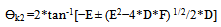 | (2) |
Where: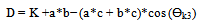 | (3) |
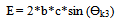 | (4) |
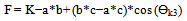 | (5) |
 | (6) |
Obtaining Ɵk2, hence Ɵs can be calculated as, | (7) |
Where:β = constant = 108oFrom Ɵs, the deflection of the spring is, | (8) |
Where,e = constant = 15 mmFinally, the force on the spring, obtained from its calibration chart is, | (9) |
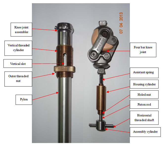 | Figure 1. The new modified extension assistant spring housing and the external control mechanism of the initial extension assistant spring setting |
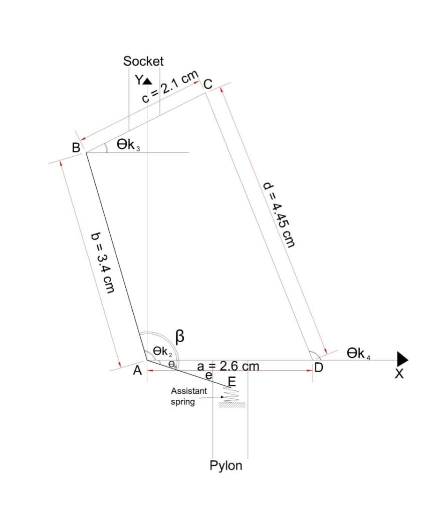 | Figure 2. Four bar mechanism, linkages and angles |
4. Experimentations
The AKA person is a 45 years old male, 95 kg weight, 1.76 m height, has a proximal thigh stump in his right limb since 1987 as an accident result. He is an active person, working all the day time wearing the present Otto Bock (3R20) four bar knee mechanism since 2005, with single axis ankle foot assembly, the foot size is 26 with full pylon length. The treadmill used is of type Zebris, FDM-T system for stance and gait analysis affording different walking speeds.The prosthetic lower limb of the amputee person is marked at the hip joint, knee joint, ankle joint and anterior and posterior points of foot with orange lighted markers to make full indication of the lower limb joint angles during complete gait cycle which are the hip angle, the knee angle and the ankle angle. A camera of type (SONY HX-1 full HD-1080) is used to capture the mobility of the prosthetic during the tested time for each test.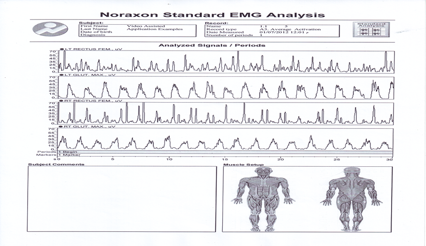 | Figure 3. Sample EMG test (walking speed = 1.1 km/hr, initial setting of assistant spring = + 2 mm) |
The tested muscles are two muscles for the amputated limb and the other two for the intact limb; these are the rectus femoris (RF) muscle which represents the sample of muscles responsible of flexing the hip joint and the gluteus maximus (GM) muscle which represents the sample of muscles responsible of extending the hip joint. Theelectromyographic activities (EMG) from four muscles are collected using myoresearch-xp clinical edition1.07.01 standard EMG analysis protocols – NORAXON-USA. By using surface EMG electrodes of type Noraxon disposable, self adhesive AG/AGCL snap of dual electrodes (4 mm) electrode with (20 mm) electrodes spacing, used for surface EMG applications only. Sample EMG chart is shown in Figure 3. The EMG tested electrodes locations which are the (RF) and (GM) area are shaved and cleaned with alcohol and dried with cotton prior to placing the electrodes. In addition to that the electrodes are fixed with adhesive tape to prevent electrode motion from the skin location during the tested time. A ground electrode was placed near sacrum area. The muscles electrodes are placed on each muscle in the picture of electrode locations presented by the Noraxon EMG software. Firstly the initial setting of the assistant spring is located at (-2 mm) from the Initial standard manufacturer spring setting and the amputee walked on treadmill at the six selected walking speeds. The selected walking speeds are chosen to represent the range of amputee walking from lower speed to the upper possible speed that the amputee can walked without problems. Each speed is tested for (30 seconds), the number of gait cycles for the selected time for each speed is different and related to the time of the gait cycle for each tested speed. The above procedure is repeated for other spring settings, namely, -1, 0, +1, +2, +3, +4, +5, +6 mm. The captured video during each test and with the aid of the orange lighted markers and the Dartfish software is used to obtain the behavior of the hip, knee, and ankle joint angles during a complete gait cycle.Using the four bar mechanism kinematics, and knowing the variation of the knee joint angle during a complete gait cycle, the force and deflection induced in the assistant spring can be obtained as variables during the complete gait cycle. Each one second walking time is divided into twenty points; each point represents 5% of the second (i.e. one frame). The time of each gait cycle (t) can be easily estimated from the duration from heel strike to toe off, and therefore the accumulated potential of the spring (AP) for each gait cycle can be calculated using the formula. | (10) |
The AP represents the applied load the amputee person exerted in each gait cycle. Increase of AP represents an increase in the load exerted by the amputee person and vice versa. EMG activity signals from the selected four hip muscles are measured for thirty seconds and sampled at 1000 Hz sampling rate and stored to the hard disk, the default signal processing consists of full wave rectification of all checked channels and smoothing using root mean square algorithm with a 100 ms time constant. The tested time is divided into a number of periods each period represent the beginning and ending marker points of each muscle activation, the number of periods depend on the speed of the amputee at each test, the marker points of each muscle activation are visually inspected. For each period the mean amplitude of the muscle activity is calculated, and then the mean of mean amplitudes of all periods is calculated. Each test is represented as EMG activity by the mean of mean amplitude of all periods.
5. Results and Discussions
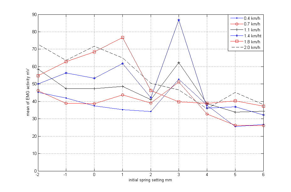
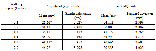
The variation of force on the assistant spring during a complete gait cycle for different walking speeds at the standard initial assistant spring setting, i.e. at 0 mm initial compression, is shown in Figure 4. The constant value of the spring force (70.65 N) from heel strike (0% gait cycle) to the knee flexion (40-55% of gait cycle) and the same for the late of swing phase (85-100% of gait cycle) represents the constant initial compression of the spring during the knee locking (knee at full extended position). The higher force from (40-55%) to (85-95%) of gait cycle represents the knee flexion at different walking speeds, late beginning of knee flexion at low walking speed (0.4 km/h) to early beginning at high walking speed(2.0 km/h) ,with late ending of knee flexion at the slow walking speed and early ending at high walking speed.The variation of the accumulated potential of the assistant spring with the walking speeds for the (standard, +1mm, +2mm and +3 mm) initial compression of the assistant spring setting is shown in Figure 5. The minimum accumulated potential at each gait cycle represents the minimum load exerted by the amputee person on the four bar knee assembly during the gait cycle at each walking speed. Energy is saved during knee flexion at the late part of stance phase and released during the knee extension at the late part of swing phase. The speed of knee return from the flexing position to the extending position depends on the accumulated deflection of the spring and on the walking speed, the time of spring deflection and spring releasing are responsible for counting the duration of the swing phase and also the walking characteristics of the amputated and intact limbs, therefore the minimum accumulated potential of spring is not the same for all walking speeds. The minimum accumulated potential at (0.4, 0.7, 1.1, 1.4, 1.8 and 2 km/h) is found to be at the following initial spring settings (+ 2mm, standard, standard, +2mm, +2mm, +2mm) respectively.The variation of the mean EMG activity at the nine tested initial assistant spring settings and for both the right (amputated) limb and the left (intact) limb of the amputee person at the tested walking speeds, is shown in Figures 6 and 7 respectively. Since the EMG results are of statistical nature, and to insure a good scatter of the data, hence the standard deviation was calculated. A sample of the calculated standard deviation, for the case of + 2 mm as initial setting of the assistant spring , is presented in Table 1. The minimum EMG activity at the right limb for (0.4, 0.7, 1.1, 1.4, 1.8, and 2.0 km/h) walking speeds happened to be at initial assistant spring settings of (+2, 0, 0, +2, +2, and +6 mm) respectively. While the minimum EMG activity at the left limb and for the same above walking speeds happened to be at initial assistant spring settings of (+5, +6, +5, +6, +6, and +4 mm) respectively.It is clear that the EMG activity of the amputated limb is, in general, less than that of the intact limb and it is less fluctuating as the initial setting of the assistant spring varies. This indicates that, in order to achieve a stable movement by the amputee, more effort is exerted by the intact limb as compared to the amputated limb.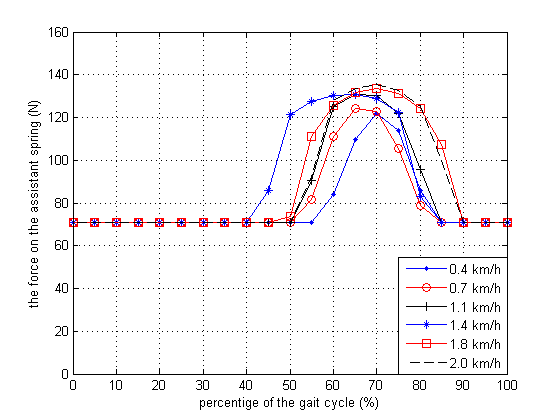 | Figure 4. Variation of applied force on the assistant spring at the standard initial setting with percentage of gait cycle |
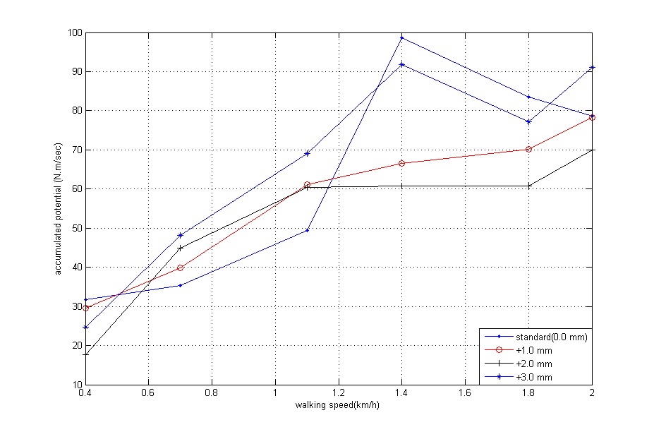 | Figure 5. Variation of the accumulated potential for different initial spring setting with the walking speed |
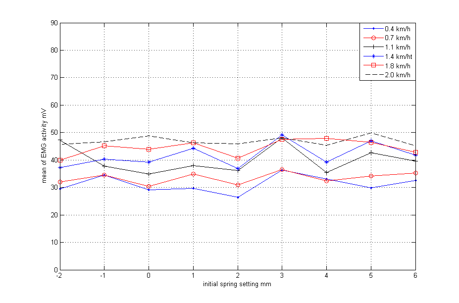 | Figure 6. Variation of mean EMG activity of amputated (right) limb at the tested speeds with the variation of initial spring setting |
 | Figure 7. Variation of mean EMG activity of intact (left) limb at the tested speeds with the variation of initial spring setting |
Table 1. Mean and standard deviation of EMG data (initial setting of assistant spring = +2 mm)
 |
| |
|
6. Conclusions
From the results of this research, one can conclude that the effort exerted by the AK amputee person, at different walking speeds, is greatly affected by the initial setting of the assistant spring in the four bar knee mechanism. Hence, as a future application, one can design and implement an electronic guided actuator to control the initial setting of the assistant spring for different walking speeds, thus producing minimum effort exerted by the amputee person.
ACKNOWLEDGMENTS
The authors wish to thank the staff of Biomechanics Laboratory, Faculty of physical Education at Babel University for their help with the experiments and valuable advises. They also thank Assist. Prof. Dr. Ali j. Abd, Faculty of physical Education at Babel University for his help in installing the software of the used programs and helping us in making the experimental tests. They finally thank the staff of biomechanics laboratory, faculty of physical education at the University of Baghdad, Jadiriya and specially Prof. Dr. Sareih A. AL-Fadly.
References
| [1] | A. Bar, G. Ishai, P. Meretsky and Y.Korent ,"Adaptive Micro Computer Control of An Artificial Knee in Level Walking", Journal of Biomedical Engineering,vol:5, pp: 145-150, April-1983. |
| [2] | J. S. RIETMAN, K. POSTEMA and J. H. B. GEERTZEN, "Gait Analysis in Prosthetics: Opinions, Ideas and Conclusions" Prosthetics and Orthotics International, vol: 26, pp: 50-57, 1-April-2002. |
| [3] | Liang Song, Xitai Wang, Siyuan Gong, Zengguang Shi, Lingling Chen, "Design of Active Artificial knee Joint", Asian–Pacific Conference on Medical and Biological Engineering ( APCMBE ) ,vol:19, PP:155-157,2008. |
| [4] | A. A. Torki, M. F. Taher, Abdalla Sayed Ahmed ,"Design And Implementation of A Swing Phase Control System for A Prosthetic Knee", Biomedical engineering conference , CIBEC, IEEE, vol:978,No:1,pp:1-4, – Cairo ,18-20 Dec-2008. |
| [5] | Alex Sadra Olivera de Cerqueira, Edward Yuji Yamaguti, Luis Mochizki, Alberto Carlos Amadio and Julio Cerca Serrao, "Ground Reaction Force and Electromyographic Activity of Transfemoral Amputee Gait: a Case Study", Brazilian Journal of Kinanthropometry and Human Performance, vol: 15, No: 1, pp: 16-26, 2013. |
| [6] | Donald R. Myers, and Gordon D. Moskowitz , "Myoelectric Pattern Recognition for Use in the Volitional Control of Above-Knee Prostheses", IEEE Transactions on Systems ,Man, and Cybernetics, vol:11,No.4,April-1981. |
| [7] | Croline O Keefe Honours Project NCPO, "Muscle Activation Patterns in the Transtibial Amputee", Monash Rehabilitation Technology Research Unit, Rehab Tech, Australia, 1998. |
| [8] | Dewen Jin, Ruihong Zhang , Jishuan Zhang , Rencheng Wang and William A. Gruver, "An Intelligent Above Knee Prostheses with EMG Based Terrain Identification", EEE International Conference,vol:3,pp:1859-1864,2000. |
| [9] | E.C. Wentink , S.I. Beijen, H.J. Hermens, J.S. Rietman and P.H. Veltink, "Intention detection of gait initiation using EMG and kinematic data", Elsevier Journal of Biomechanics Gait and Posture, 2012. |
| [10] | Lingling Chen, Peng Yang, Linan Zu, and Yanli Geng, "The influence of walking speed on muscle activity of thigh and application in prostheses control",36th Annual Conference on IEEE Industrial ElectronicSociety,IECON,pp:2714-2718,7-10-nov.-2012. |
 Abstract
 Reference
 Full-Text PDF
 Full-text HTML